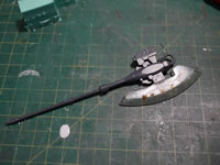
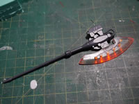
A few days ago, I posted about making clear resin heat hawk by making a mold of the existing heat hawk, then throwing in a string of LEDs in the mold when I poured the clear resin. The resin has had some time to cure and I’ve had some time to ponder the next great question. “How the hell am I going to power this damn thing up?” One of the TGG folks not so innocently asked the question. For which I honestly answered that I had no idea and that I would solve that problem eventually. I already had a few ideas, I could replace the upper handle of the axe and run some wires through there and then through the hands, through the body, and have the battery and switch assembly somewhere on the base of the project. That seemed a little too much work. Laziness is the mother of invention. I decided to completely self contain the power source as well as the switching assembly. Here’s a video of that through process and how it all works out:
After the jump, I go through the pictorial and more wordy version of what I did in the shot 6 minute long video.
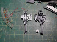
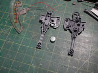
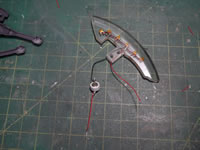
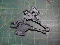
Last I left off, I had the resin curing and some wires out of the thing. Trying to figure out how to fit a 3 volt battery from my collection of power sources, I came up with creating a little battery pack using tiny 1.5 volt button batteries. Stacking the batteries, I can double the voltage. Using a styrene tube, I cut a small section and I had my battery holder. I also need to do some liposuction to the excess plastic fat inside the axe pieces. The male and female connection joints were cut away, and carefully sanded down to make room for the battery. The battery assembly is test fit and everything closes up properly, time to get the battery assembly wired.
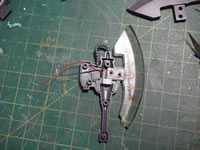
Since the battery is going to be sealed up inside the two halves, I won’t be able to get to it to swap it out, or adjust the contacts if something juggled loose. To resolve the connection issue, I soldered some metal leads that I had left over from cutting down the LED’s leads and soldered them to the positive and negative ends of the two batteries. This was slightly nerve wracking as I didn’t want to burn out the battery. So tests were done after each solder point to make sure everything still worked. Once the leads were in place, I just wire wrapped the negative end from the axe blade to the negative end of the battery and that’s one end of the equation solved.
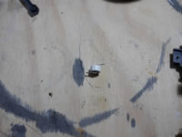
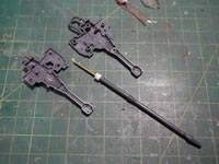
For the switch assembly, I needed to clear up more contact points. The top of the handle part is cut off as well. After clearing the space at the bottom of the axe head piece, I found a small piece of styrene tubing that fit in the area and could freely spin. I drilled into the top of the handle piece and glued the metal rod into the handle. On the other end, I measured the metal rod to fit inside the lower area of the axe head. Since I removed the contacts for the handle to the bottom of the axe head, there was a stability problem. To solve this, the metal rod works as support when the two halves of the axe head are glued together.
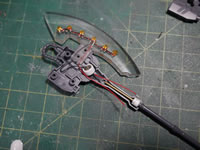
A piece of wiring is attached to half of the styrene tube. The idea here is that I have a wired wrapped to the positive end of the battery, and running down the bottom of the axe head and the positive wired from the axe blade’s LED assembly running down the other side of the bottom axe head piece; and in the middle is the handle that is now the switch assembly. A twist of the axe handle closes the connection between the two positive ends and with a complete circuit, the LEDs light up.
Here’s what that jumble of words above looks like pictorially:
Completely assembled, the battery inside, switch assembly, a simple twist of the axe handle turns the LEDs on and we’re done. I can now use this axe for any other kit I want to display with a lighted element.
This is not a difficult mod, but it just takes a little planning and visualizing for the final product. Then just taking the small steps to get there.
