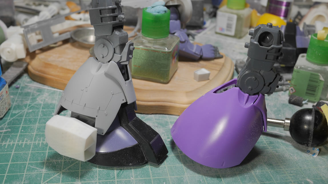
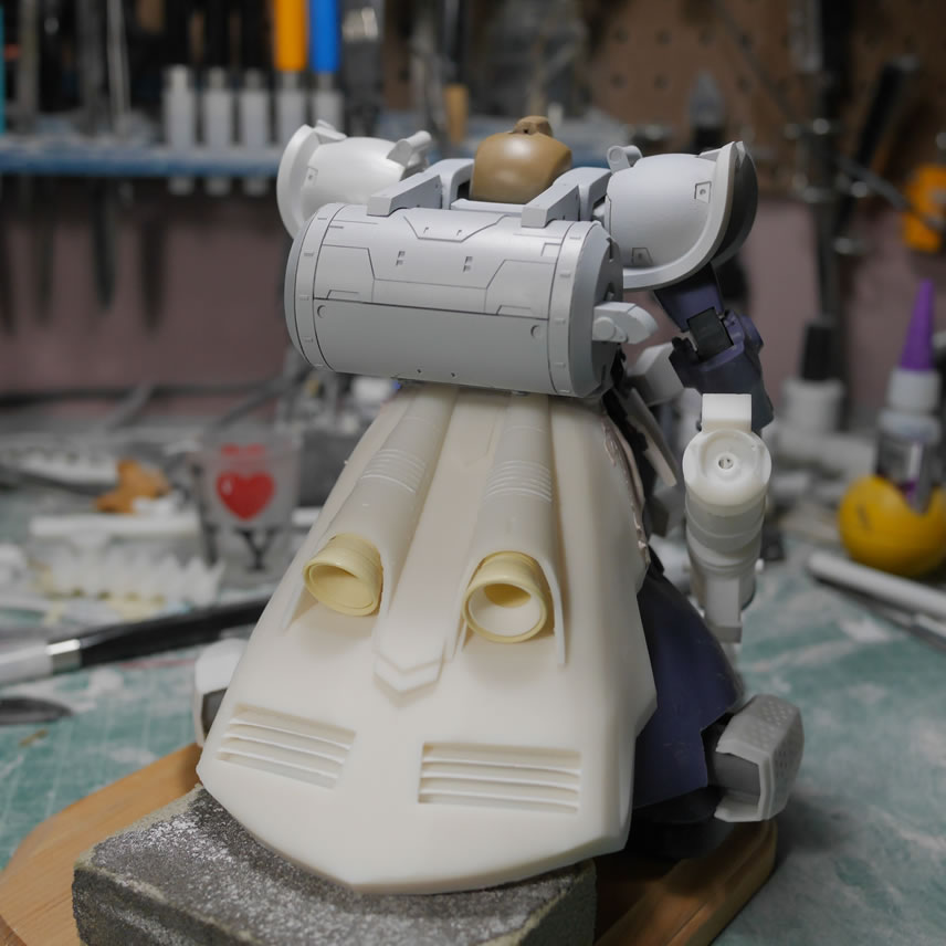
It has been a while since I made an update. Real life got a little busy with a trip to Toronto for a wedding and just being busy. I’ve been getting work here and there with bits and pieces. One of the major bits is the skirt. I had used the original skirt and tons of bondo and plastic to build up the rear skirt. My skills with Blender has gotten better and some slow down at work tempted me to try designing the skirt. Printed out, it’s not perfect and it’s slightly heavier than the bondo version, but it look fairly decent. There is still a decent amount of work needed to meld the piece with the waist which was easier with the bondo piece because it was built up from the original rear skirt. Here is the skirt and a quick mock up with the kit.
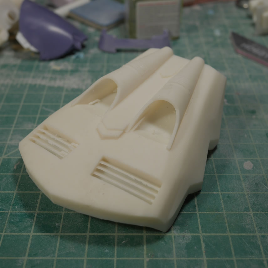
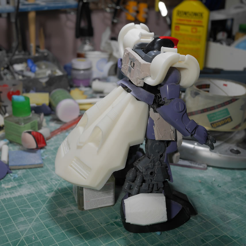
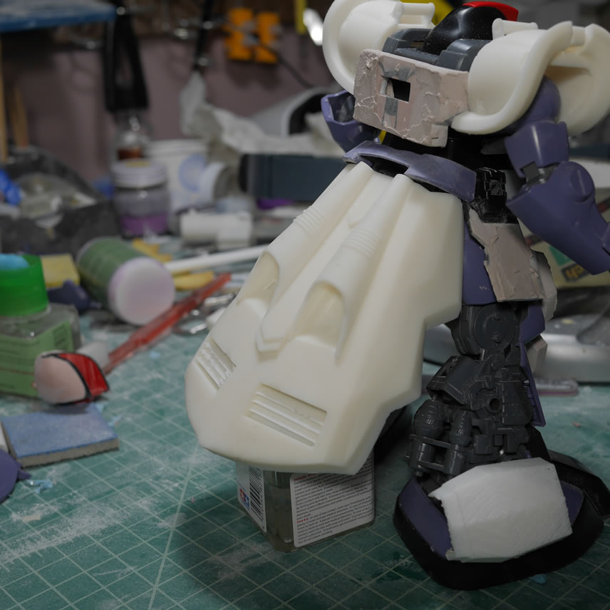
This update is fairly large since it has been over a month and a half since my last update. So there’s much more after the jump!
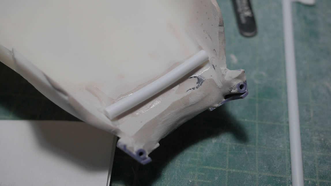
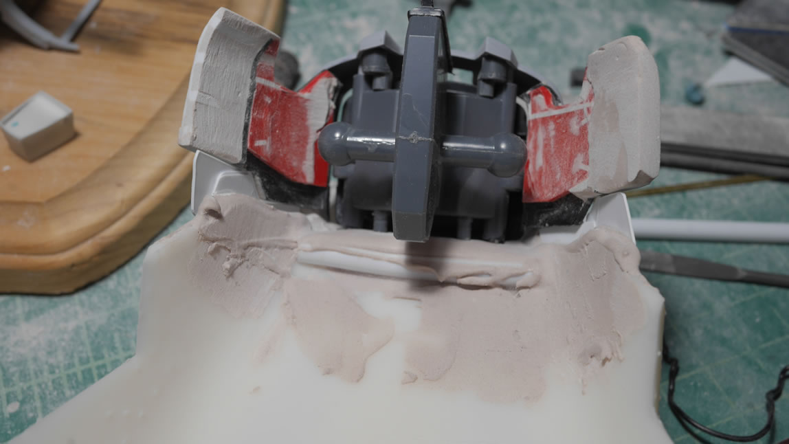
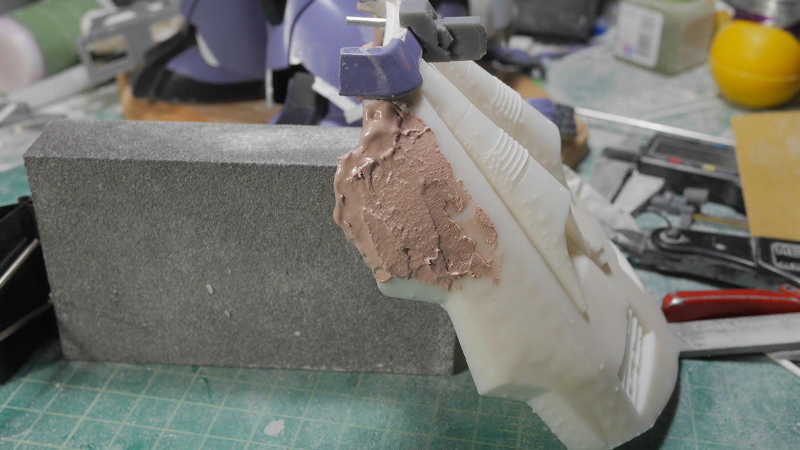
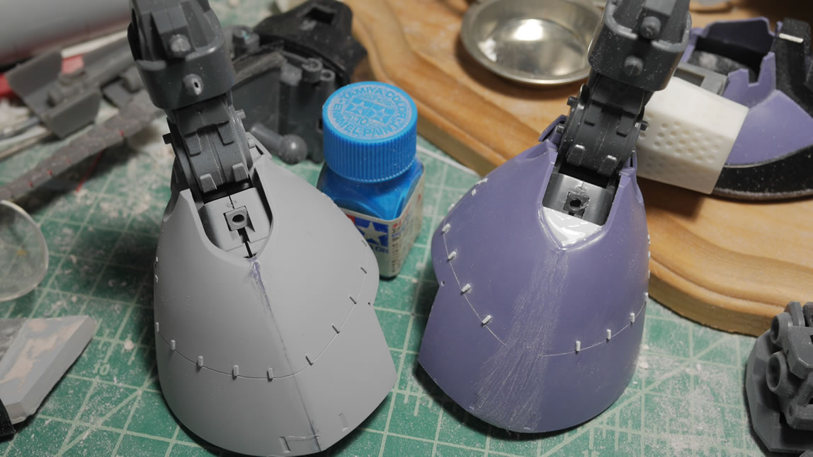
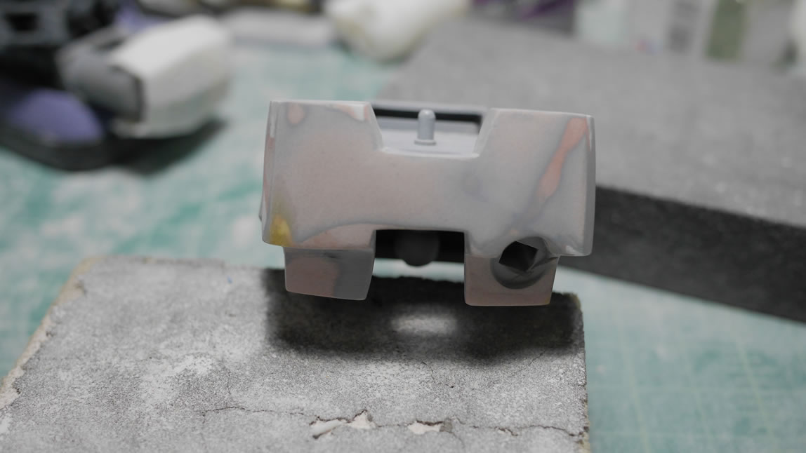
Returning to the printed skirt, I glued in a support beam (plastic tube) and then built up some bondo so that I can fill in some gaps between the original top skirt piece(purple plastic bit) and the printed skirt piece. The bondo also works to add surface for drilling in some holes for new support points to the kit’s waist unit. The waist unit’s contact points are measured against the rear skirt and the new holes are drilled. There are some gaps between the rear skirt and the side skirts, so some base plastic plates are glued to the rear skirt that will eventually be used to support a layer or two of bondo.
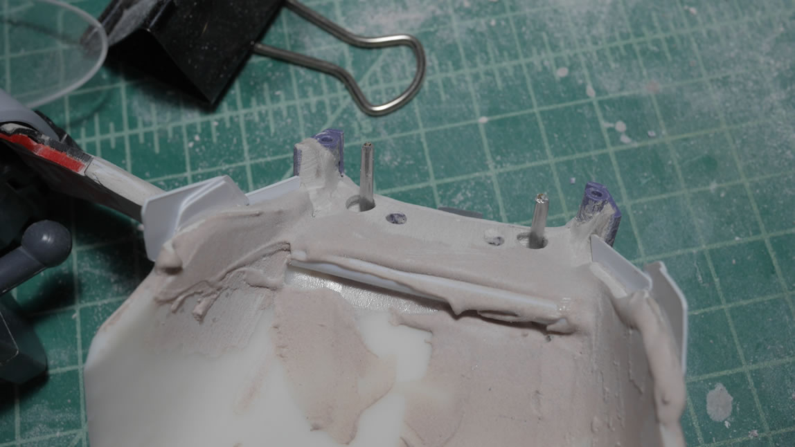
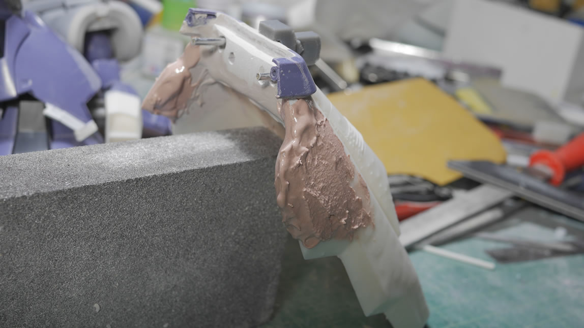
The next step, once the above support layer of bondo cured, is to drill the holes and add in some brass/aluminum rods as the new connection points. These also work as support since the damn rear skirt is pretty heavy. Bondo is applied to the sides to build up those sides of the rear skirt where those points meet up with the side skirts.
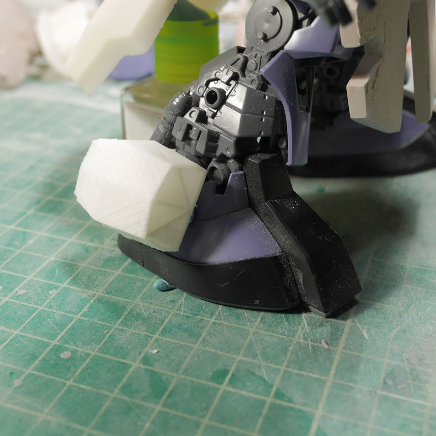
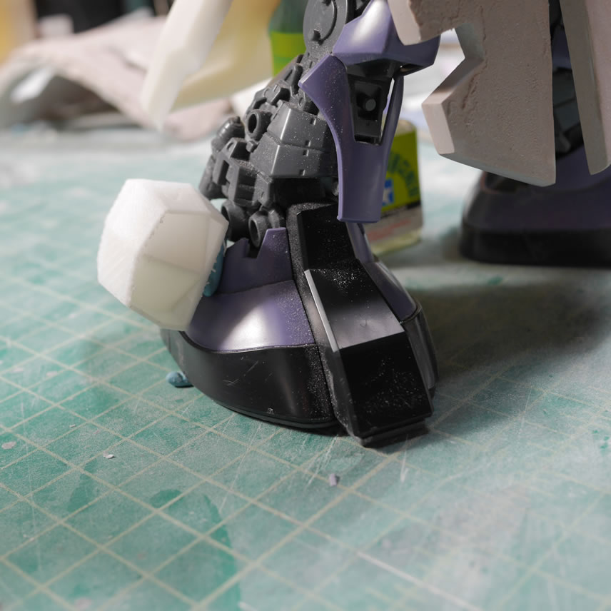
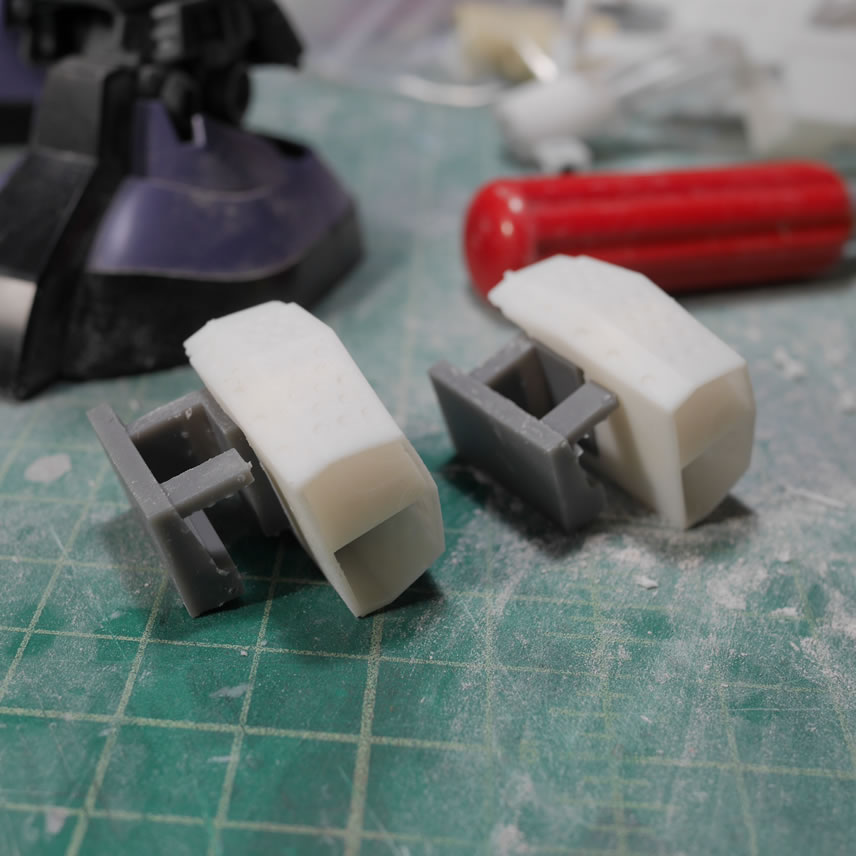
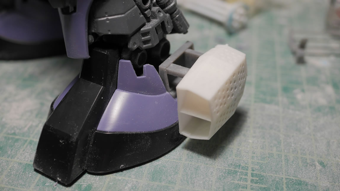
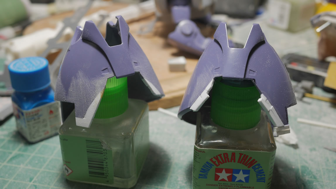
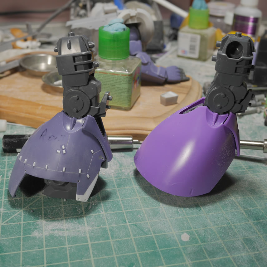
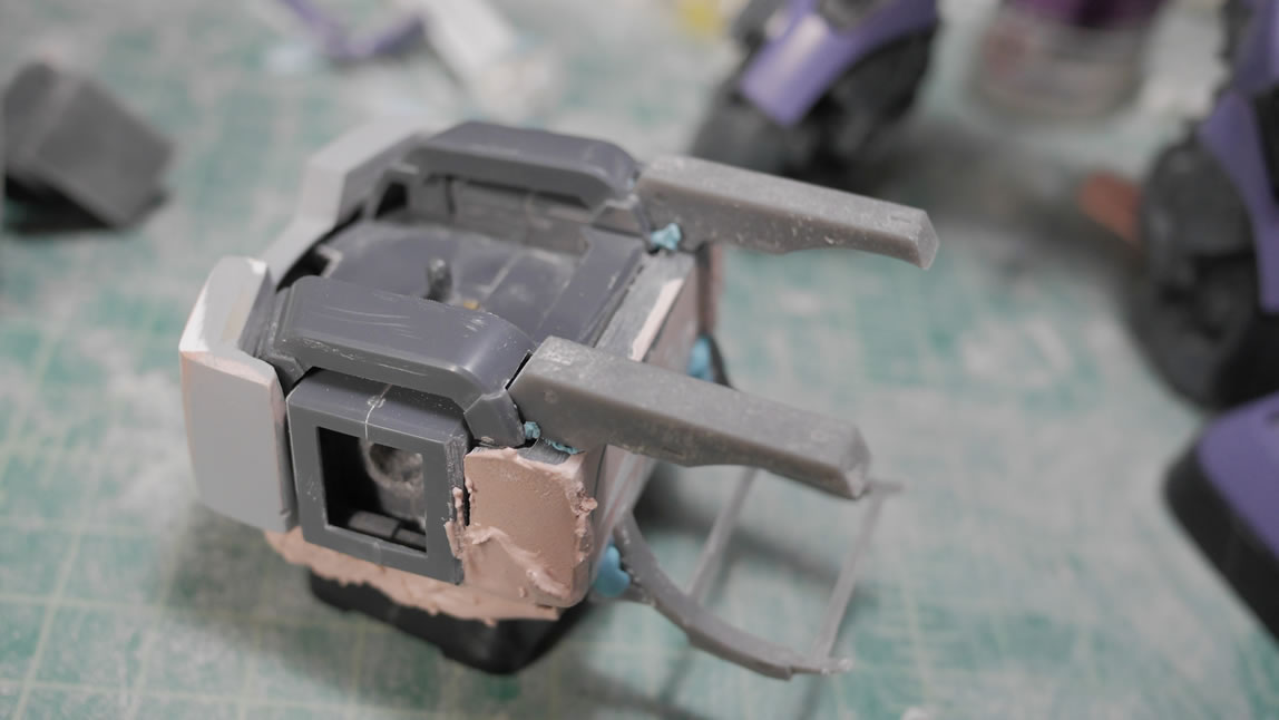
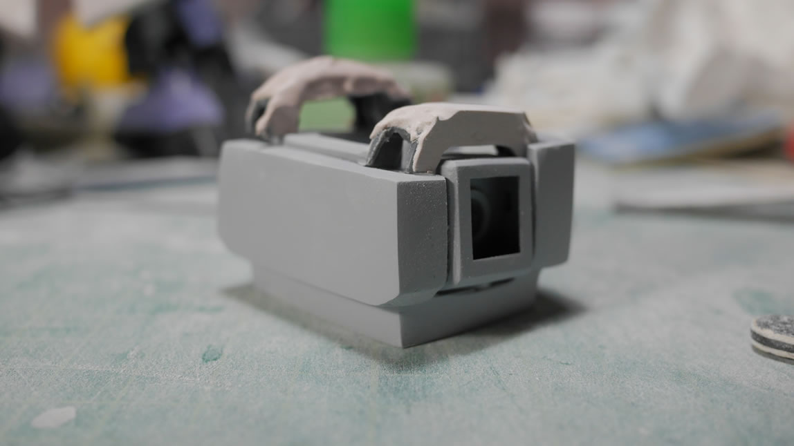
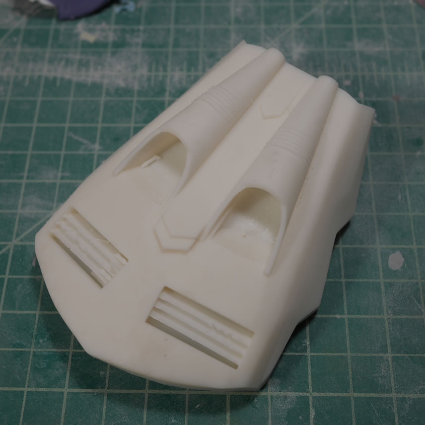
Moving on to the feet. The last post touched on the 3D designed foot vents that is similar to the Dom Trop’s foot vents. Since this kit is probably closer to the Dom Trop than the standard Dom, a decent amount of work is necessary to modify the legs and feet. With the vents pointed, I did a quick size and test fit against the feet to make sure the look correct.
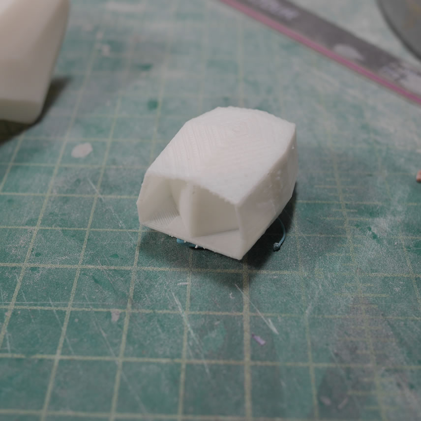
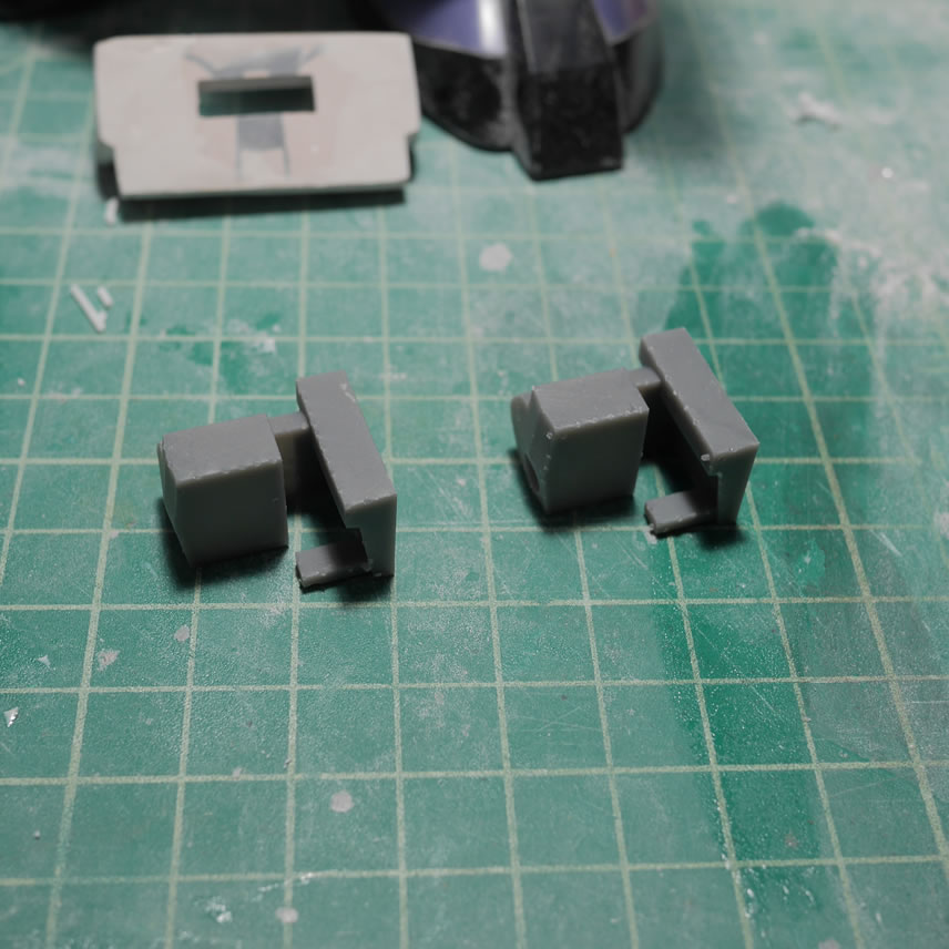
I designed and printed a connector joint that attaches the vents to the feet. My previous progress post talked about printing mirrors of objects so we don’t run into issues of two left feet pieces. With that resolved, I now need to make mods to the feet so that the connectors and the vents fit and look correct.
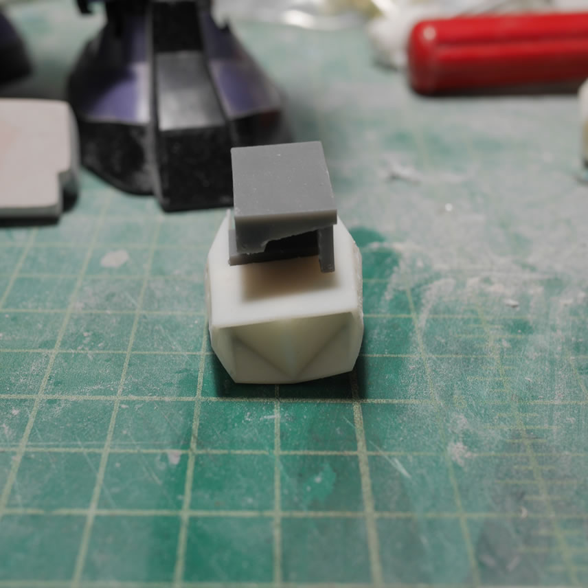
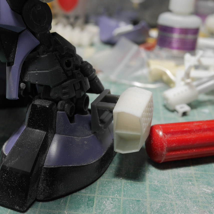
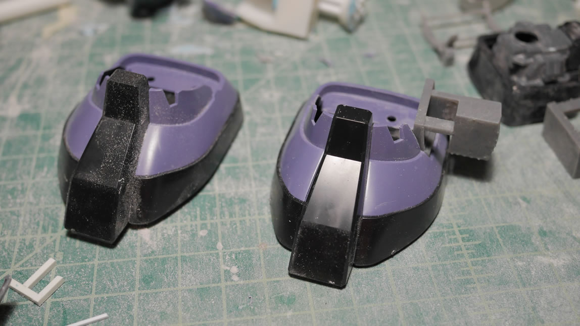
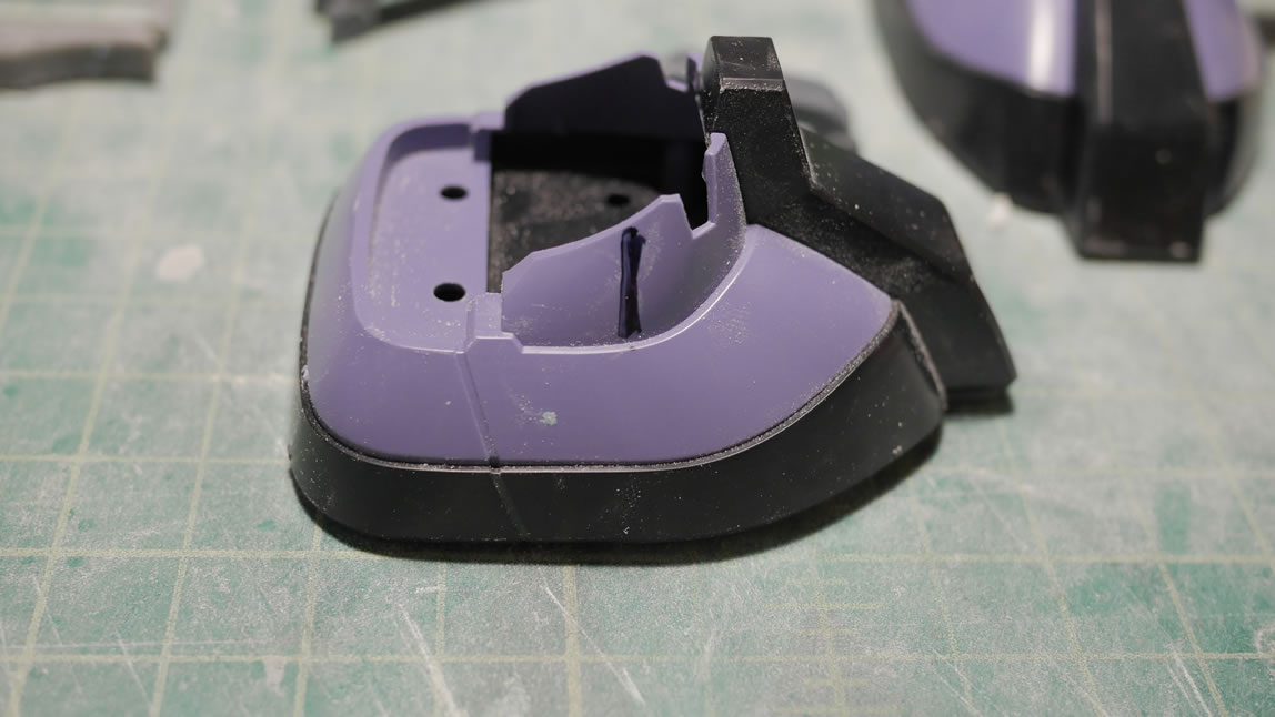
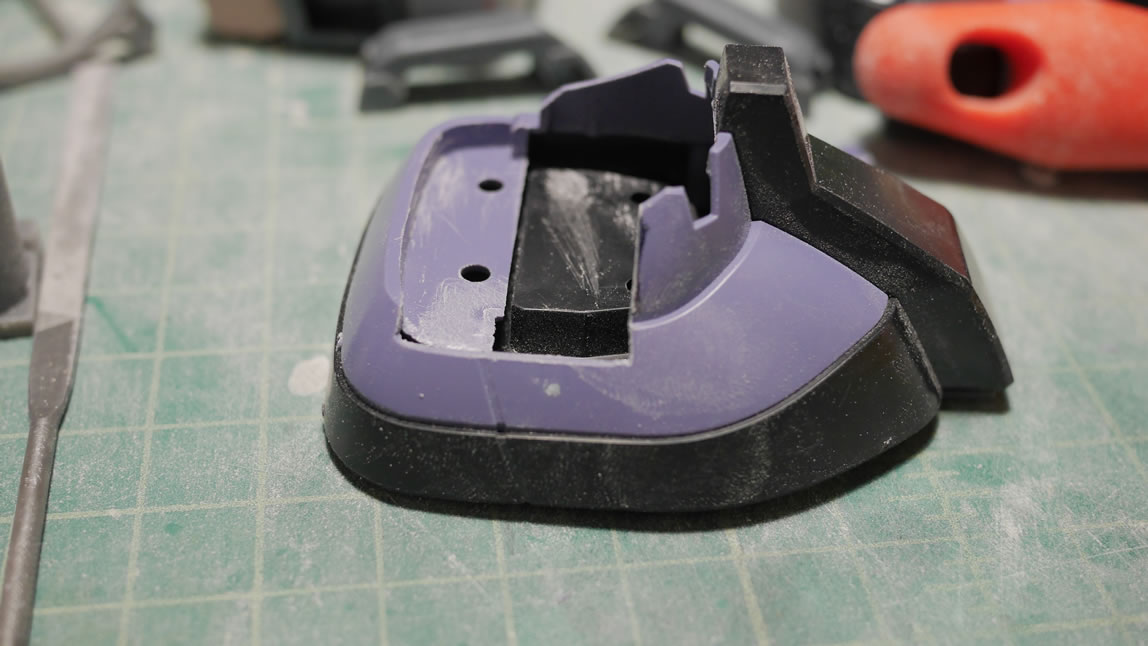
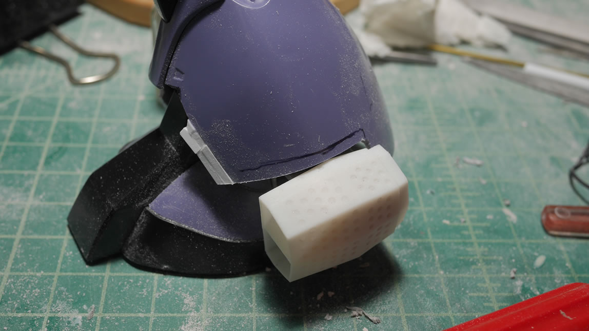
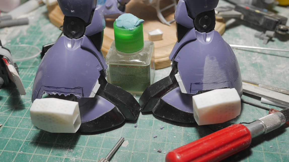
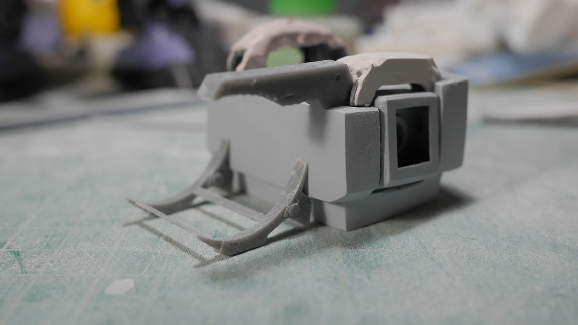
I cut the outside sides of the feet to fit in the connector and vent piece. Cut, sand, test fit, and repeat until the joint fits correctly. Once done, I glued the connector piece into place. The vent parts are just being held to the connector joint with some sticky tack.
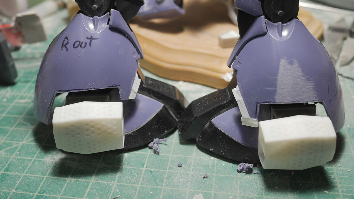
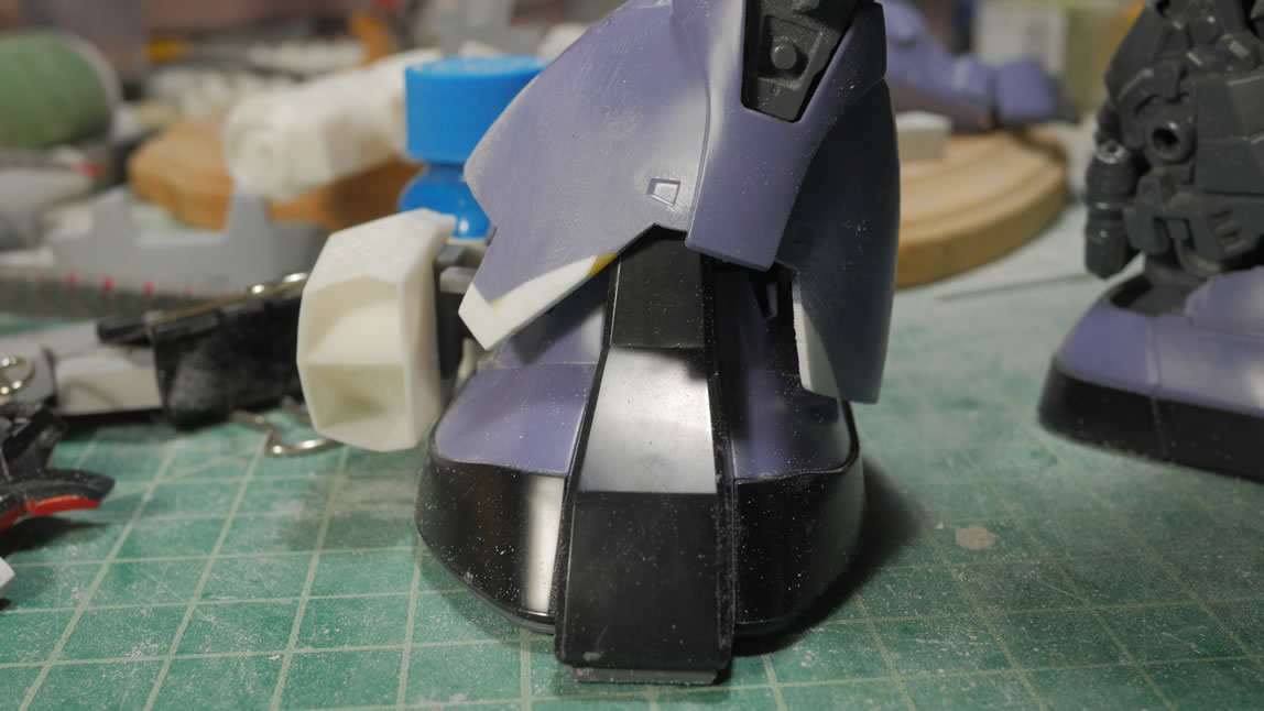
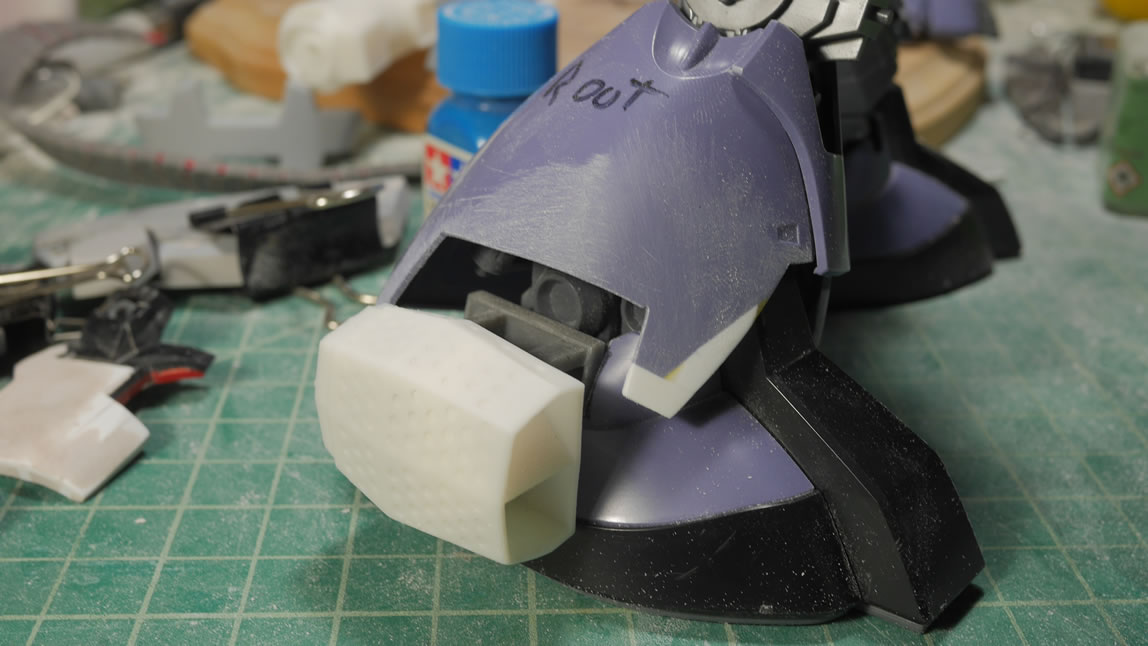
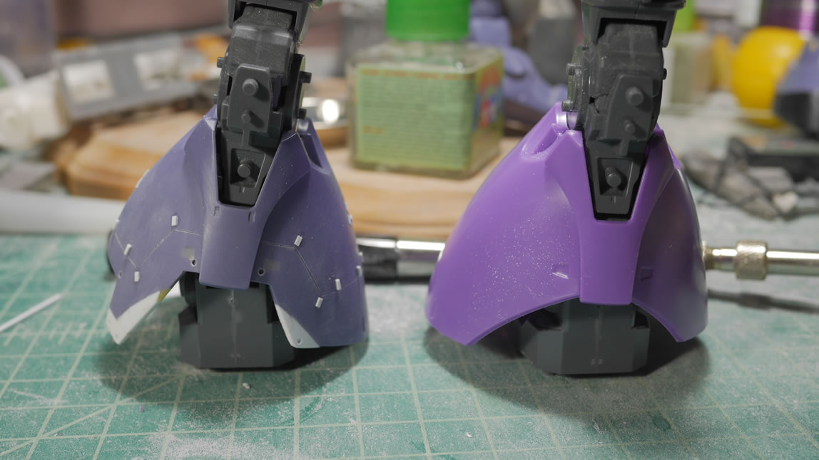
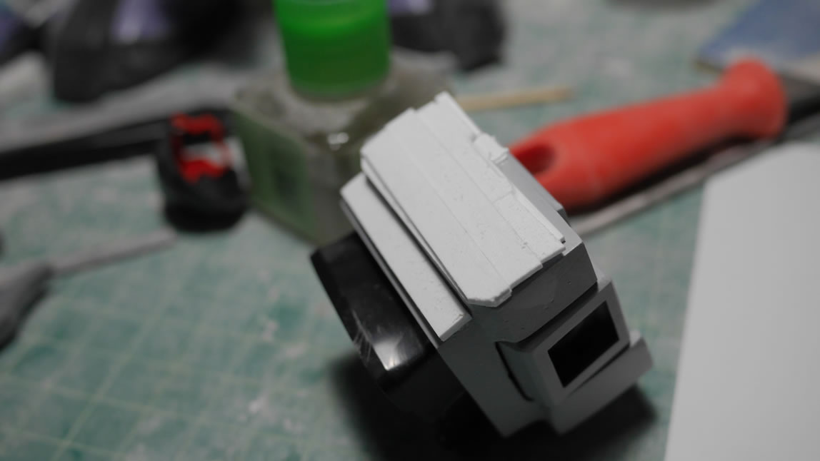
The legs got some cuts and plastic glued several weeks ago. Time to revisit and start working on the legs. I measured and drew some guides for cutting the outer areas of the legs. I have the legs labeled clearly to make sure the correct area and correct legs are being cut. The plastic glued to the front of the legs gets some sand work to shape it. Some plastic is cut away, and some plastic is added, and a sanding stick works to shape everything.
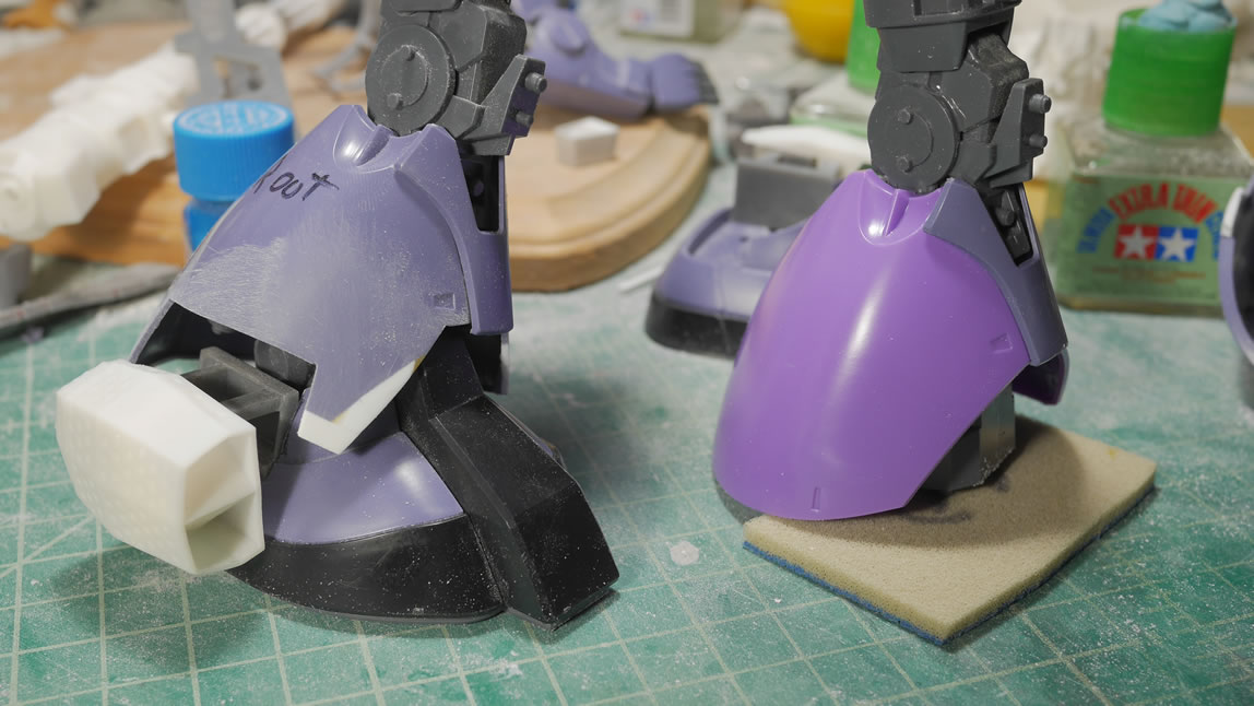
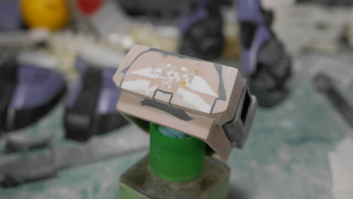
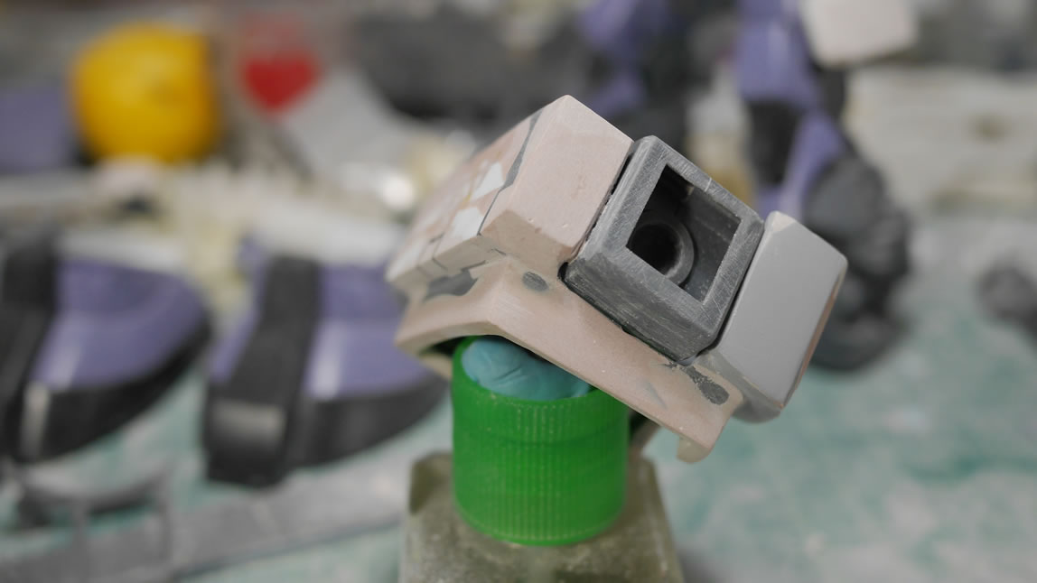
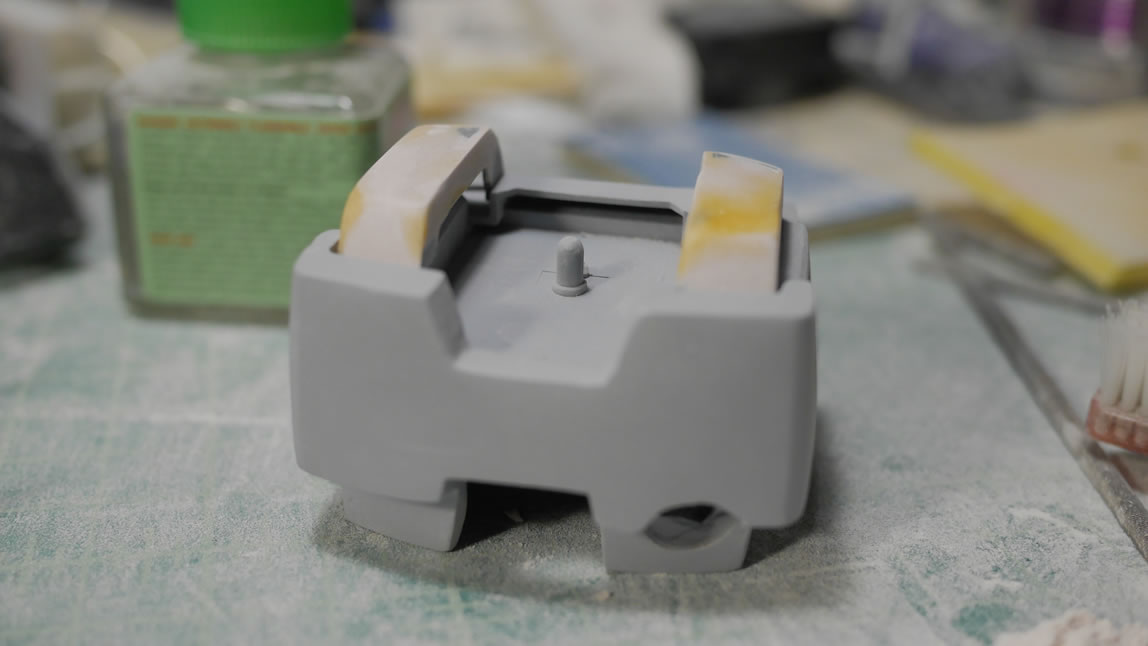
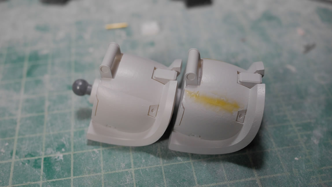
More test fitting with the feet to ensure everything looks correct with the reference pictures I have. Light curing putty (the yellow bits) is used to quickly fill and sand the surface. The last picture is a comparison with the original Dom’s leg to see differences.
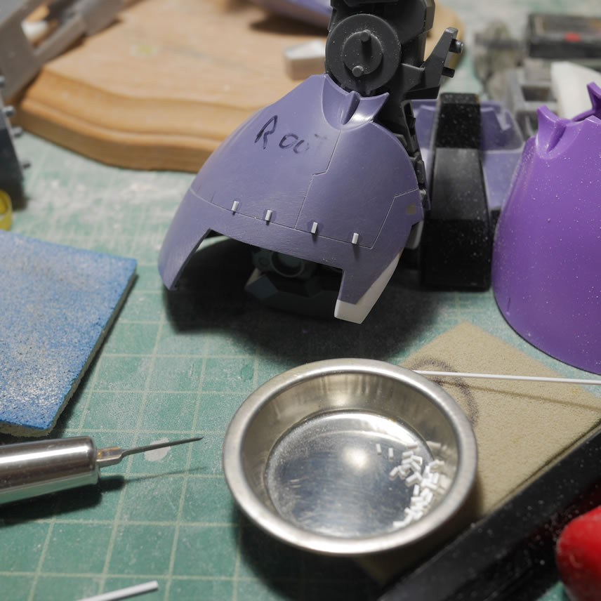
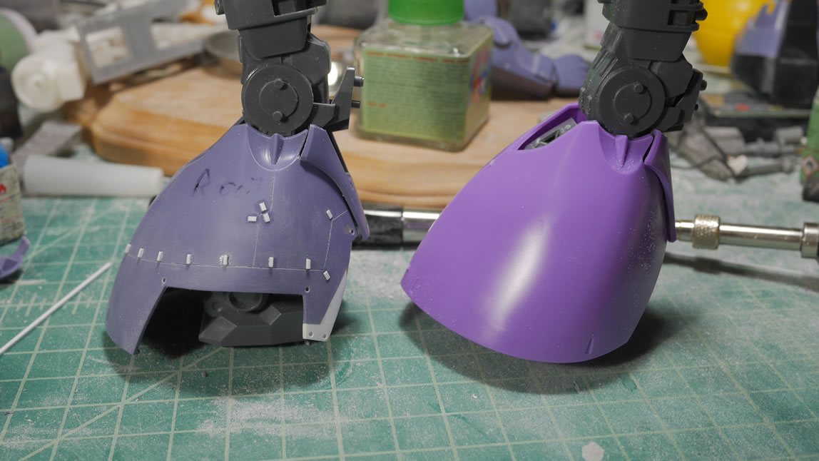
Once the base shapes are cleaned up, time to get into detailing the legs. I scribed in some lines with the BMC chisel and dyno label tape as well as tamiya masking tape as guides. The lines were measured and drawn in pencil first to check for the look. Once the look and measurements were correct, the lines were taped up and the chisel run. I first started with the .2mm chisel. Once I removed the tape and sanded the surface a bit to clean up some rough edges, I found that the lines were a little too thin, so I carefully went over the lines with a .3mm chisel. The lines really show up much clearer after a layer of primer. I laid down some tamiya tape and measured out 5 mm marks and then used this as a guide to lay down marks on the legs for the raised details. The source reference shows scribed details and I didn’t want to scribe all those little details, so I went with raised details instead. The Chopper II from Northwest Short Line was used to precisely cut identail pieces of plastic details. A note as of this post, NWSL is planning on closing their doors forever in the next few months, so if you haven’t picked up the Chopper II, DO IT, <arnold s.>”GET DA CHOPPA!”</arnold s.>
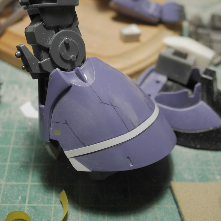
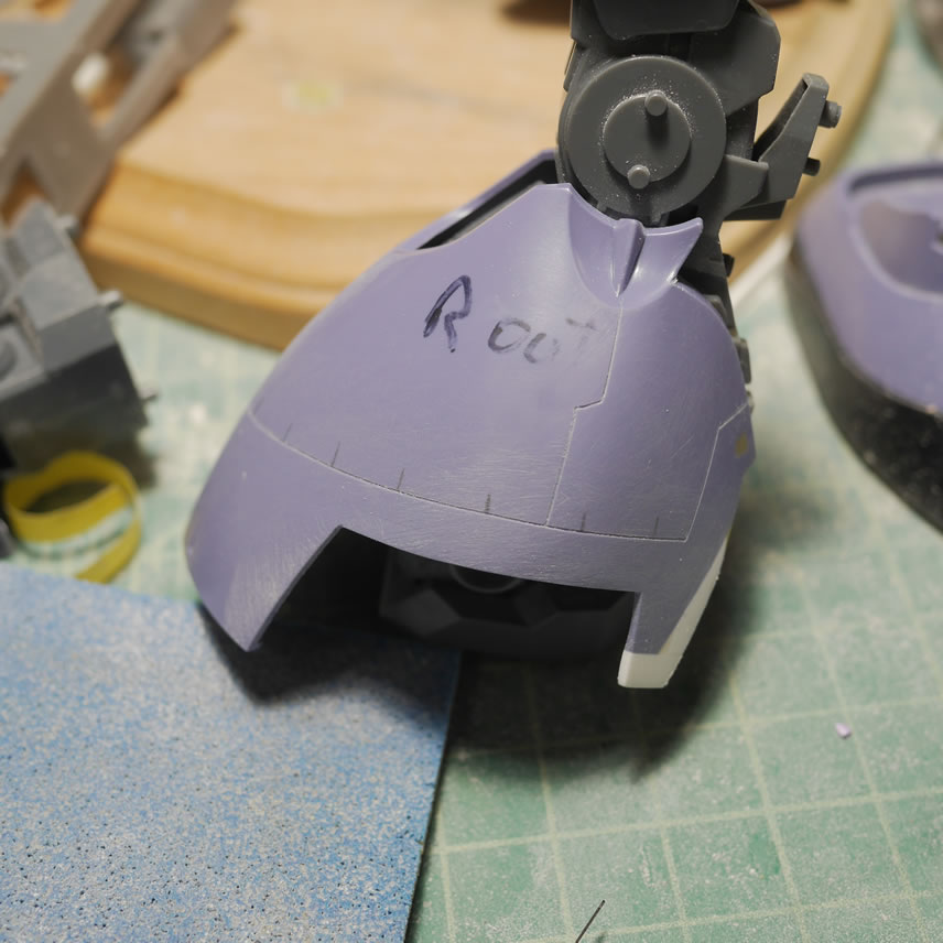
The detailing done, or so I had thought, I took some comparison shots with the OOB Dom leg.
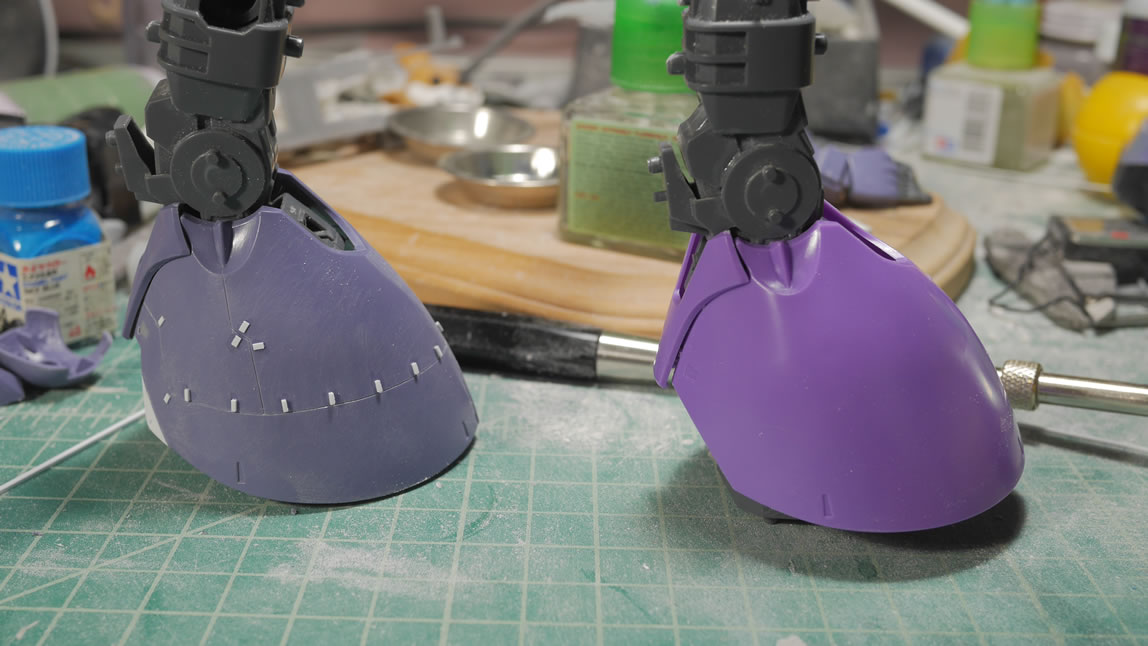
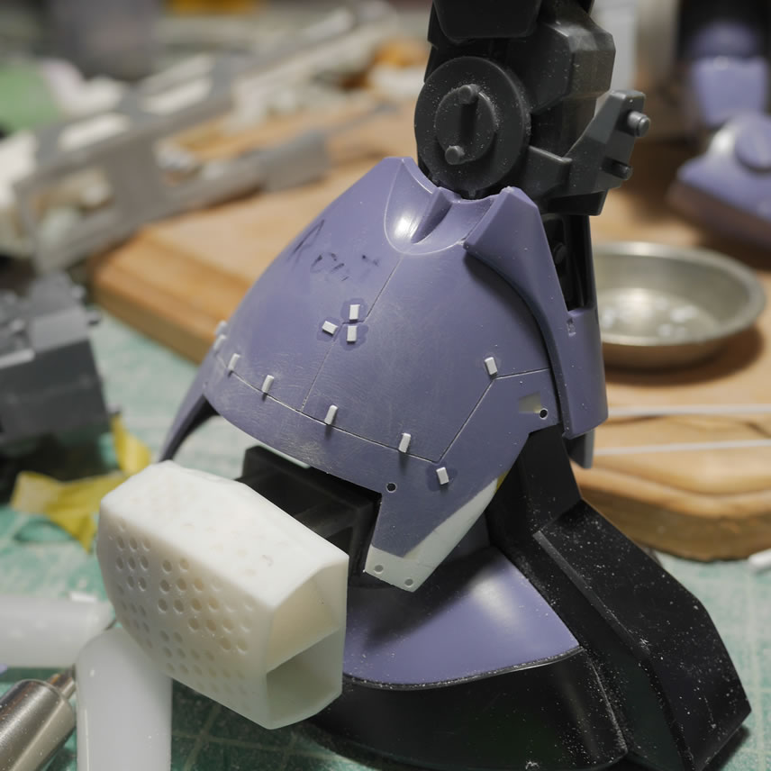
Once primed, all the off colored bits tie together and the scribed lines really pop. I also drilled out some detail bits that I beveled slightly with a rounded jewelers grinding bit. Looking at more reference pictures, I saw that the back of the legs were also different, so I’m currently in the process of fixing that with the glued in styrene at the lower back knee area. The two halves of the legs are also glued together since the leg armor is a whole piece and not split down the middle. There is also more scribing, but that will come after I get this mod done.
Moving back to the top half of the body, the chest needed more refinement. I start to work on the back of the chest block and just ended up gluing the front and back chest armor to the chest block. Seams need to be fixed as well as the difference in building up the two halves separately are glaringly obvious.
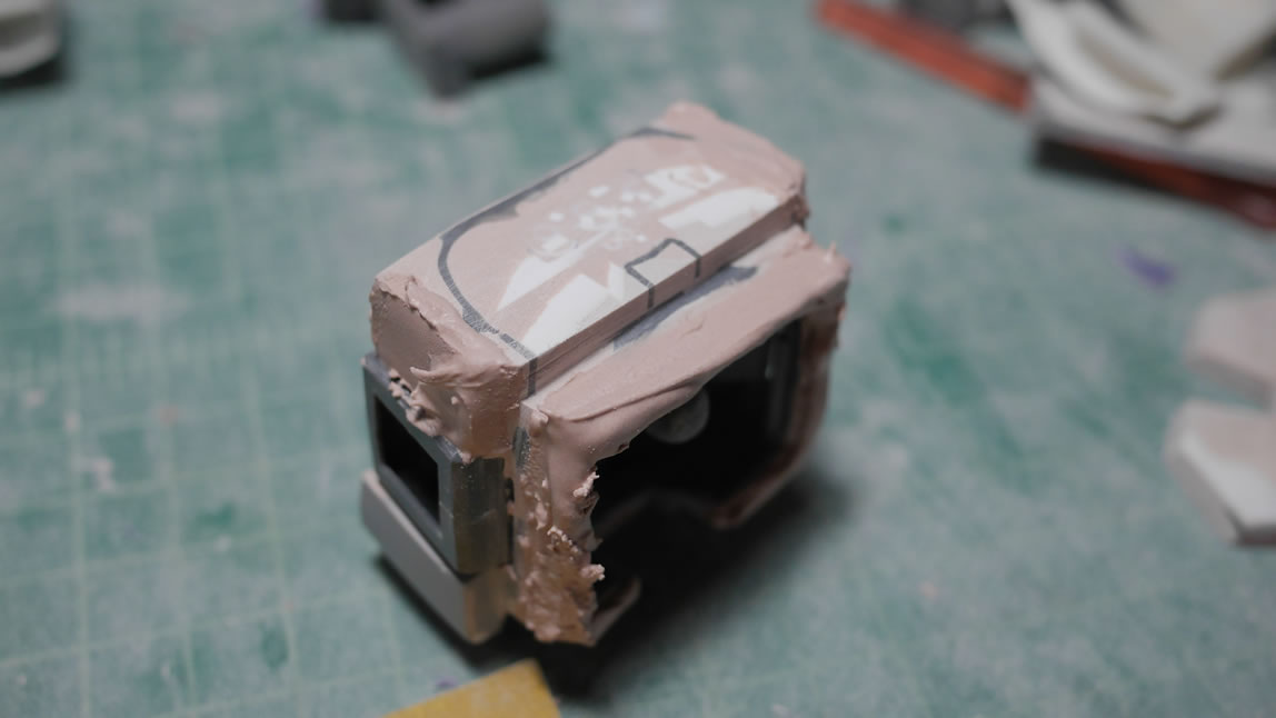
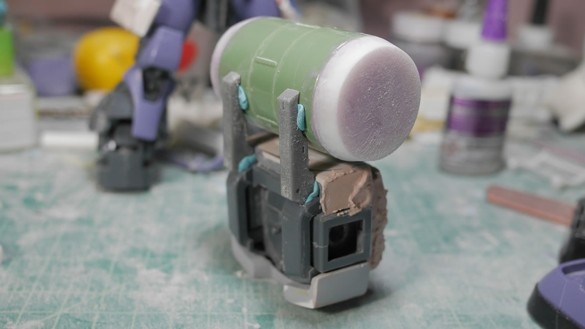
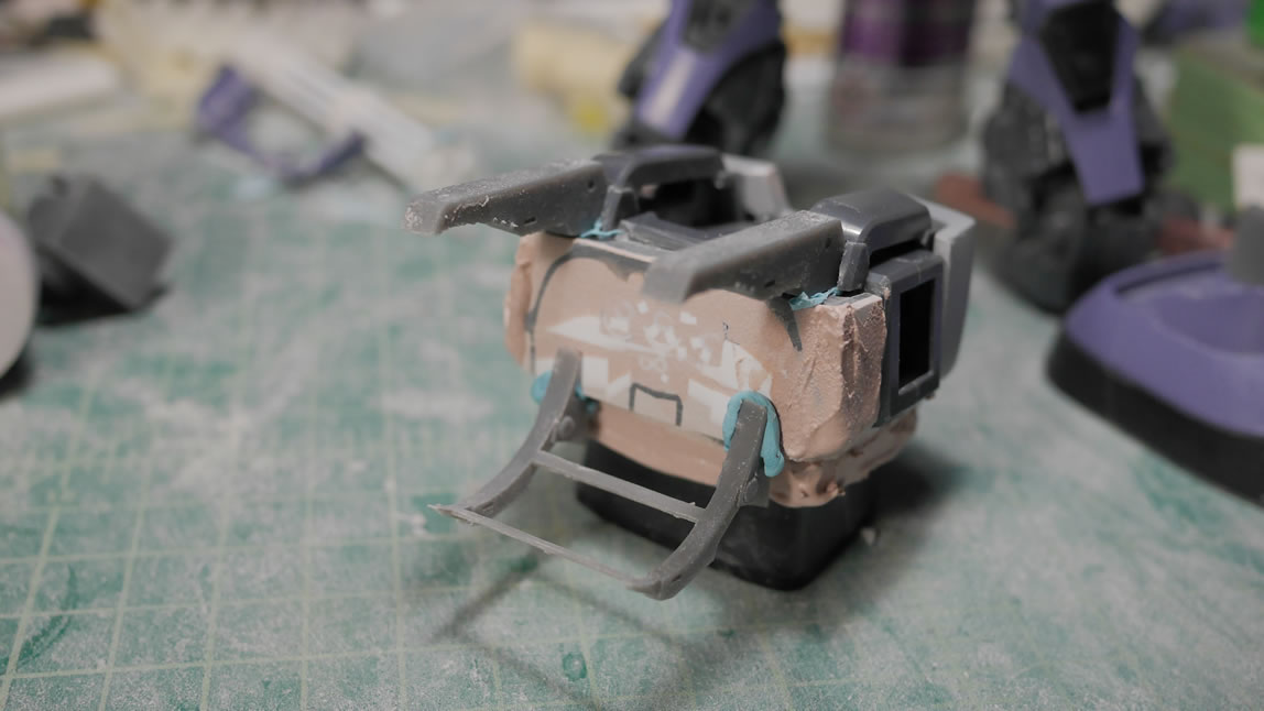
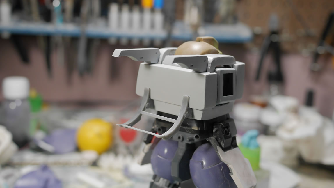
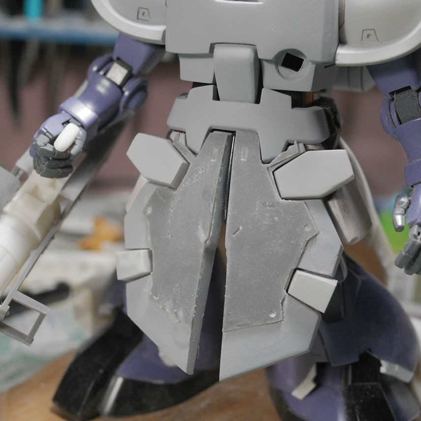
The previous posted saw the prints for the ammo drum attachment racks. Here, I’m mocking up the attachments to the back and doing a ton of test fitting to make sure it all looks correct and fits. Sticky tack is great here as a quick adhesive. The only problem is that the fit isn’t exact with the sticky tack, you get a general feel, but not the exact fit since the sticky tack has surface area of its own.
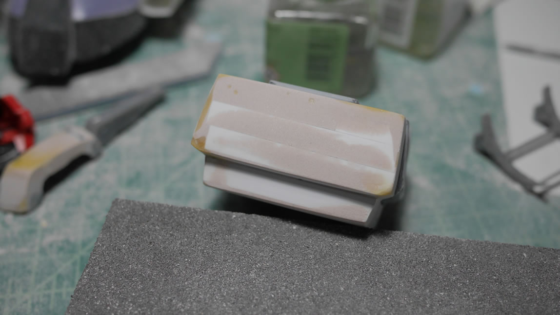
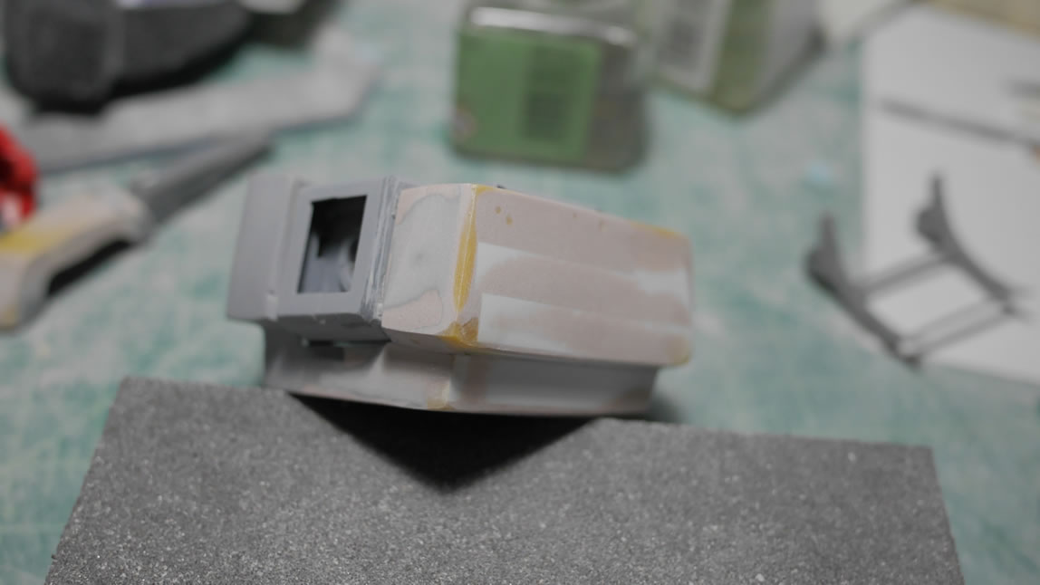
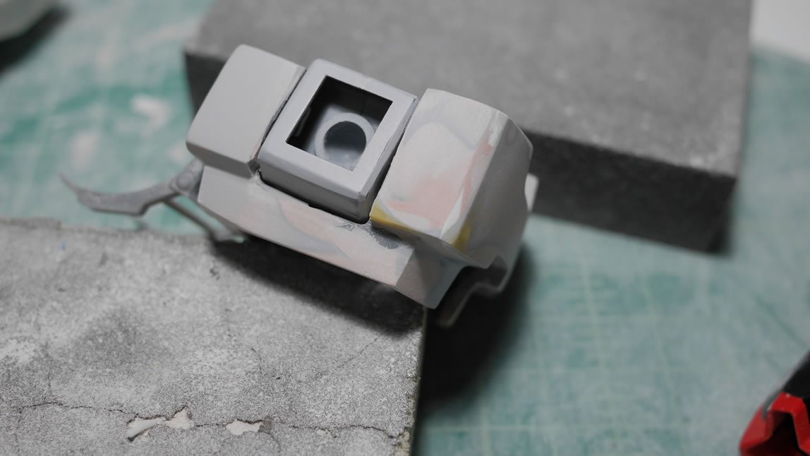
Test fit, test fit, and test fit. I also start to fill in some of the pits and pot marks on the chest block with light curing putty. In the middle of a build session, it’s tough to have to apply a putty and wait the full day or how ever many hours required for said putty to cure. Light curing putty works very well for small fixes and even small sculpting bits and doesn’t completely interrupt the flow of the build session.
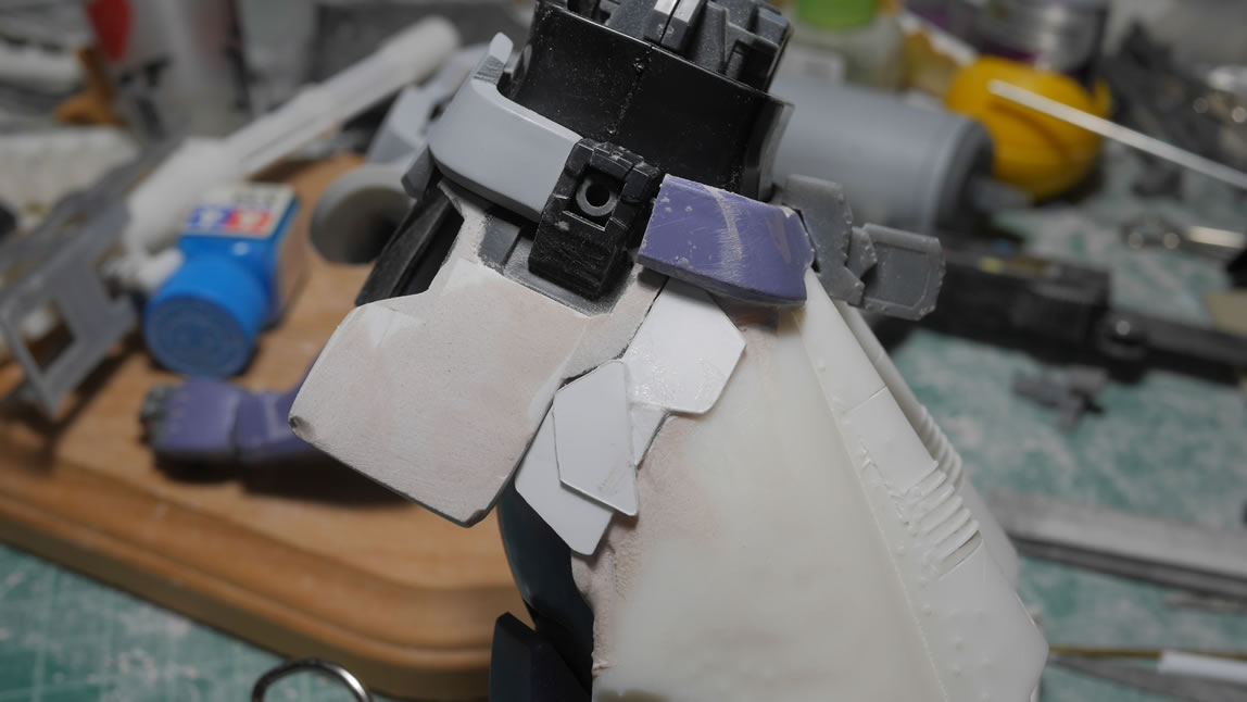
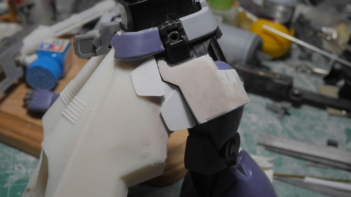
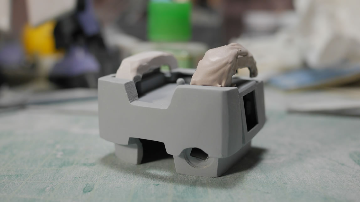
The Dom’s original shoulder straps were too rounded in comparison to the blockly Barrage style suspenders. Bondo is employed to build up the area and sanding sticks and metal files to shape it. And in the last picture, more light curing putty to keep the sanding and shaping process going. If I’m nearing the end of my build session, I’ll use a cheaper putty and just let that sit over night since I’m done building. In the middle of the build? Light curing putty all day long.
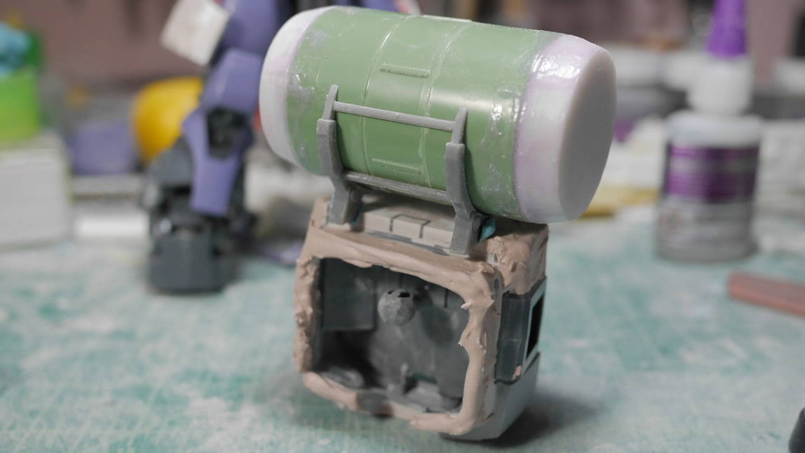
After the test fitting with the ammo drum and the attachment bits, fit required adding plastic to the back to fill gaps and fine tune the look. I glued in some plastic strips and added some putty to fill in these gap areas. With the added size in the back, another test fit is done to check the fit and gaps.
The following day, the back bit is sanded, puttied, and sanded to shape everything. Test fit, test fit, test fit.
And more detail sanding and light curing putty work to get closer to the final sculpt of things. Once satisfied, the lower attachment piece is glued into position.
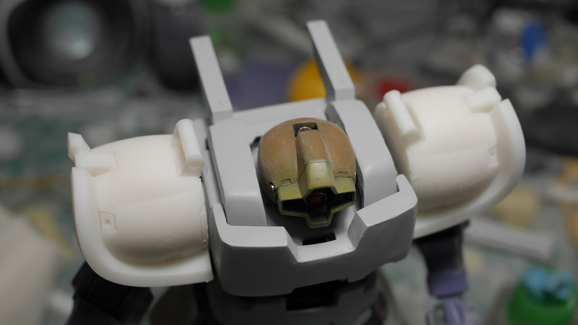
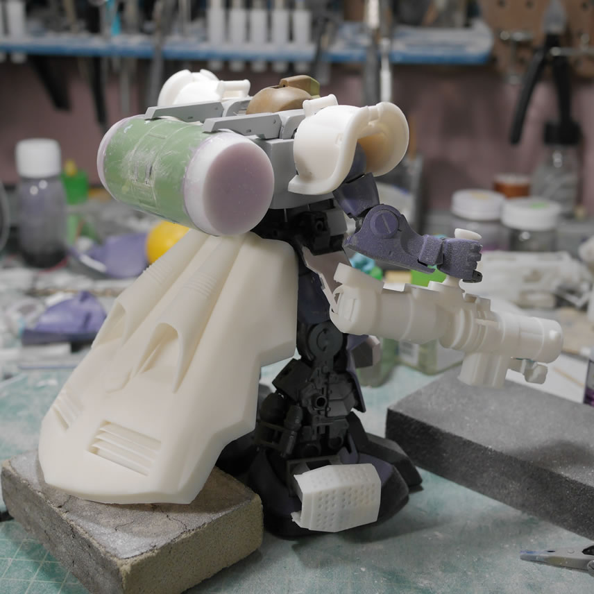
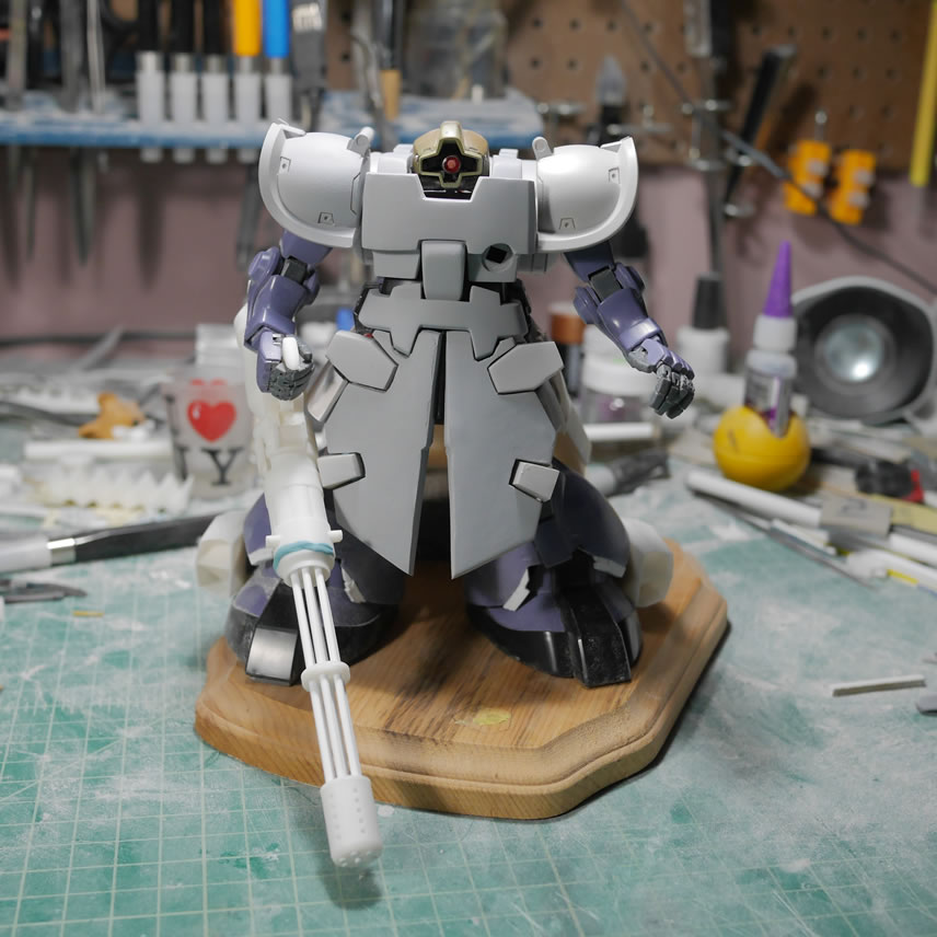
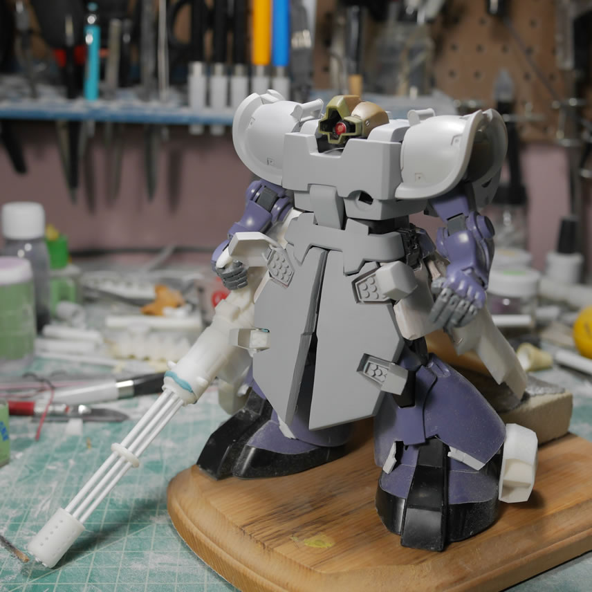
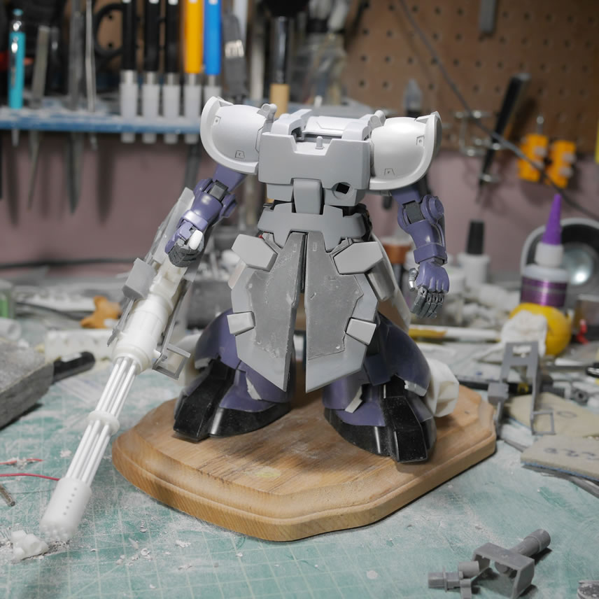
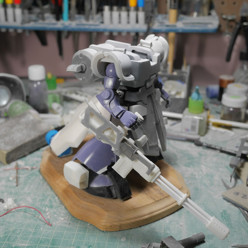
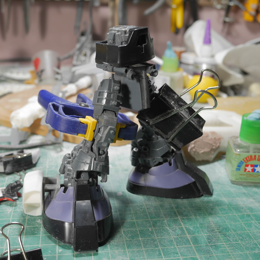
Another quick dress rehearsal with most of the principal parts to make sure everything is still fitting together. Working on small sections at a time, it is easy to forget the big picture, and it is always good to revisit that big picture. Plus, it works as a nice story piece once this is finished to watch the progression as a whole.
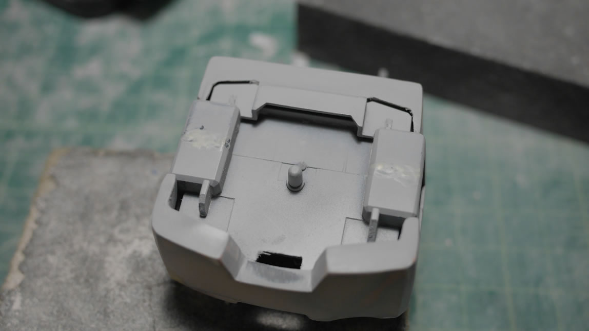
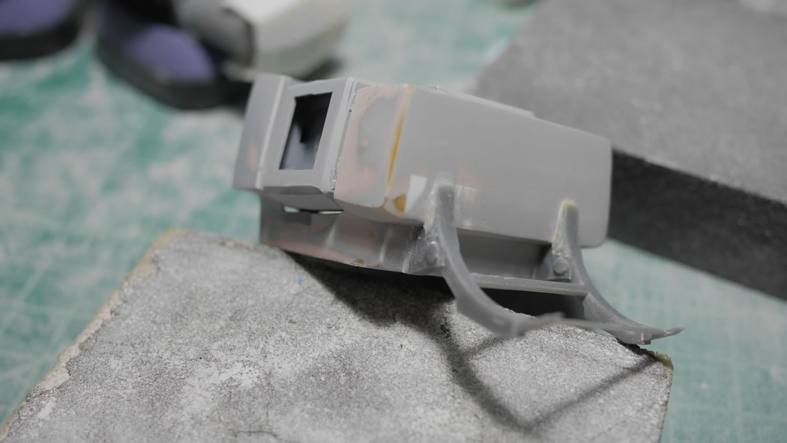
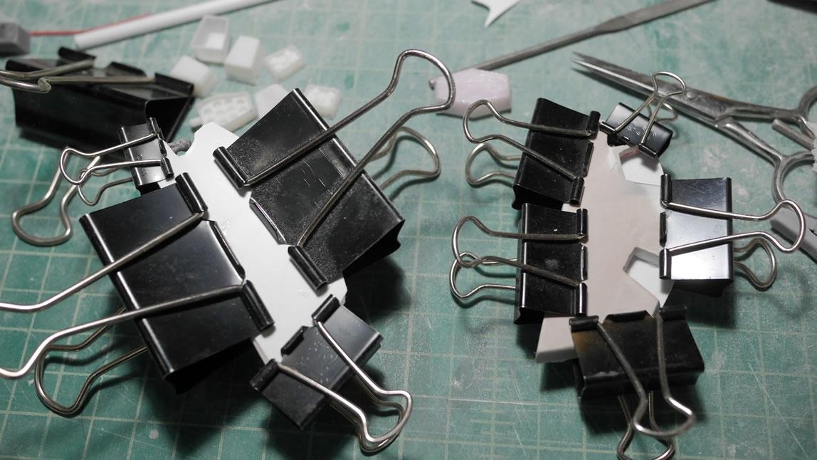
Moving from the upper torso, we go down a level to the front skirts. The back side is sanded but not polished and finished since it is only a surface to glue a plastic backing. The backing will be where the missile pods attach. And I can also easily scribe the surface as well as easily glue styrene details to the plastic. Glueing to the mostly bondo works best with CA glue or even an epoxy glue. For detail work, I’d much rather use styrene on styrene with plastic cement. Paper clips are used to hold the parts together while the backing glue cures.
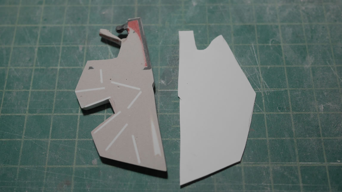
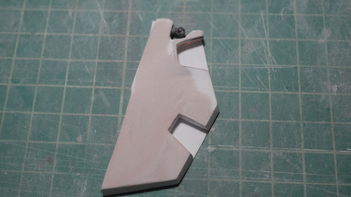
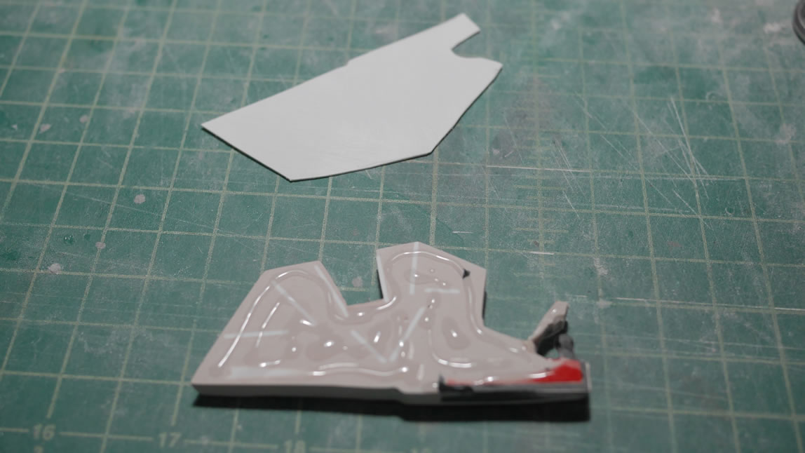
And I completely forgot to snap pictures of the front skirt detail pieces I designed and printed. I wanted a small raised surface with the details in the front skirt, so I designed and printed. The resin is a bit brittle and easily broke, but once glued, I can fix everything in post (later).
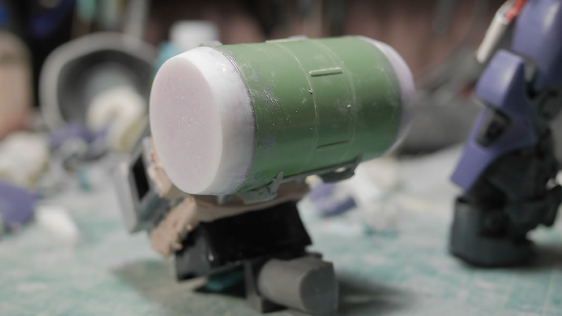
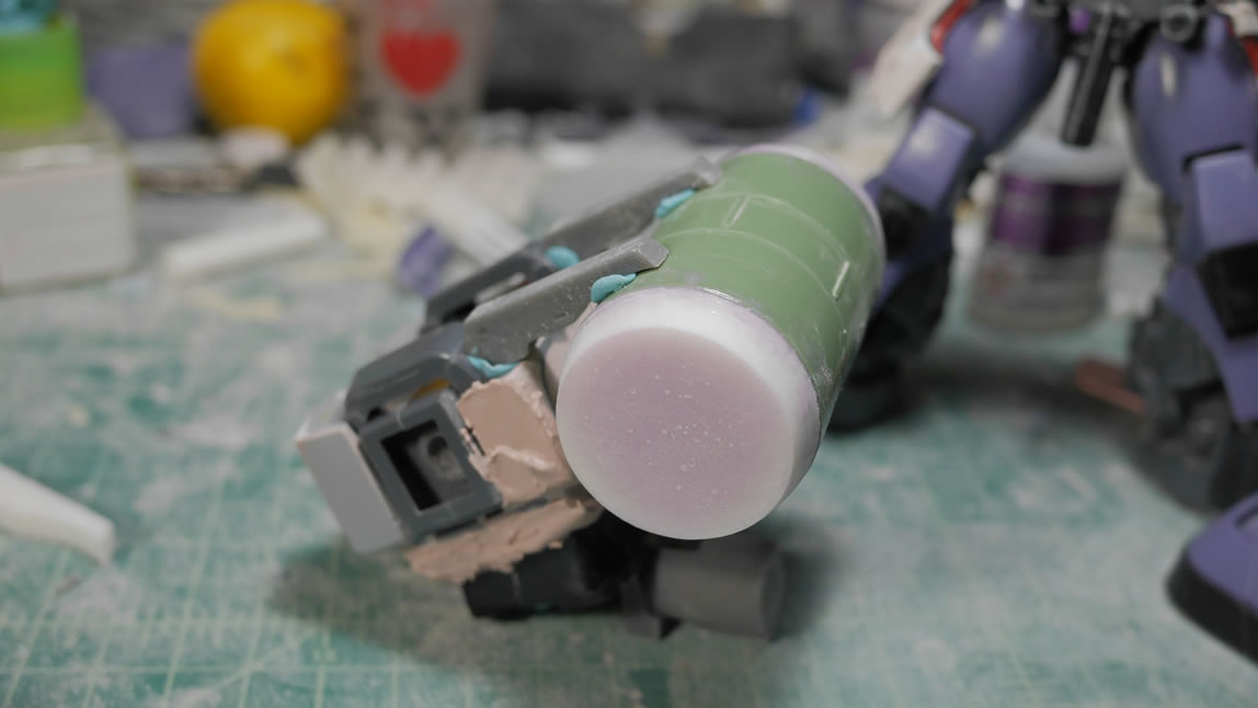
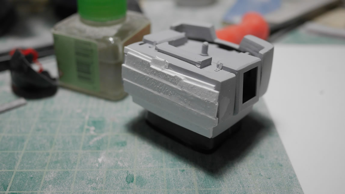
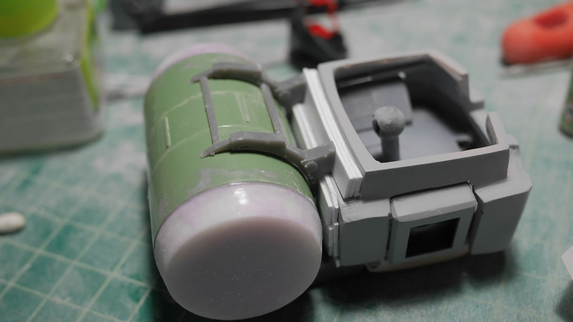
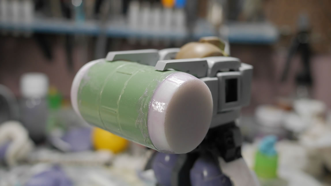
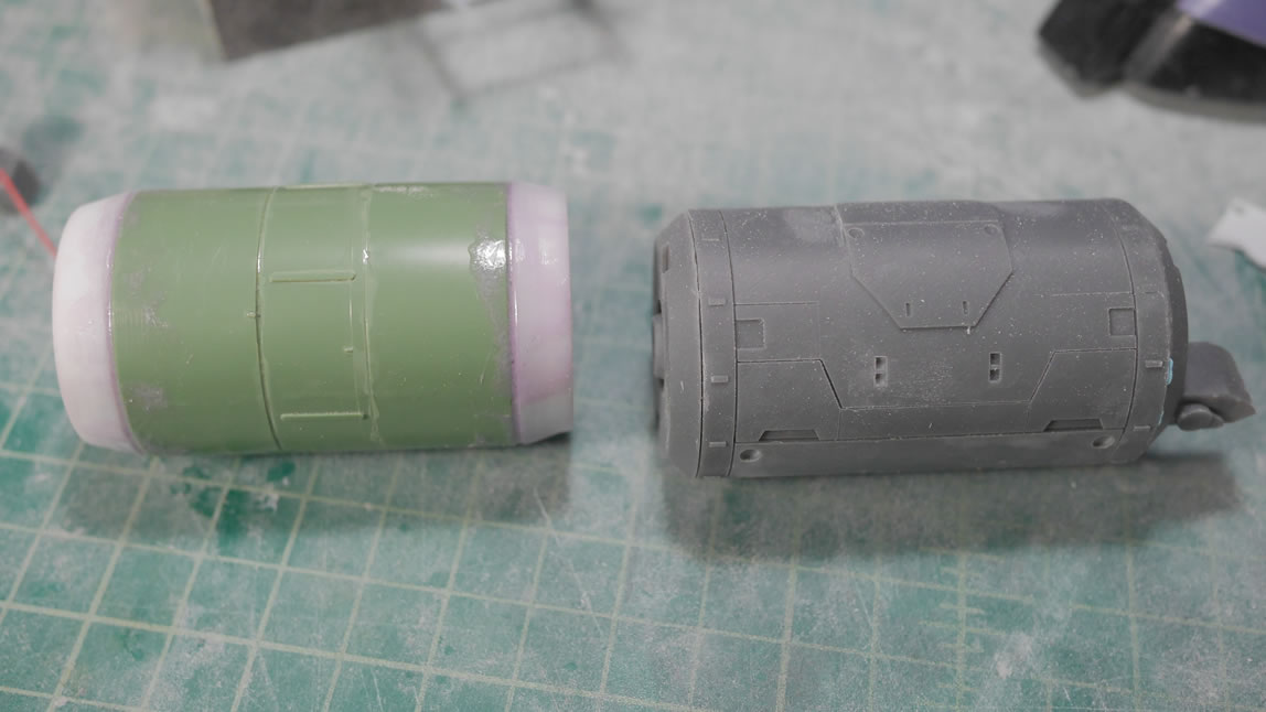
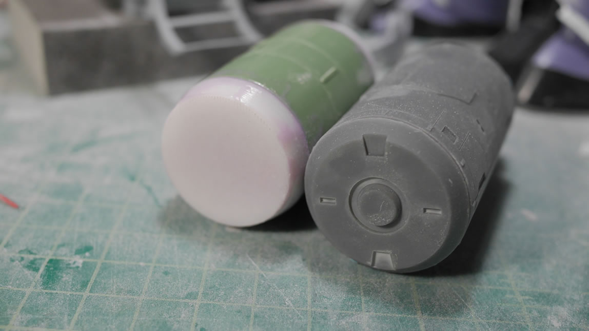
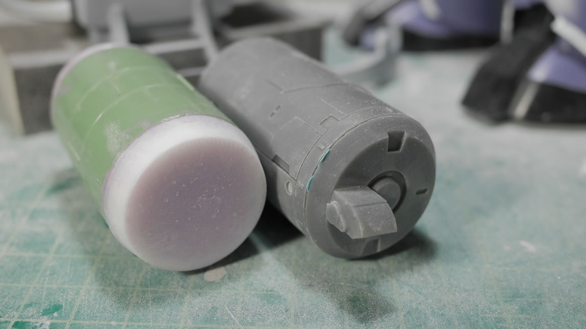
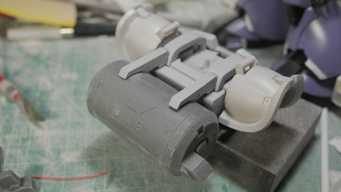
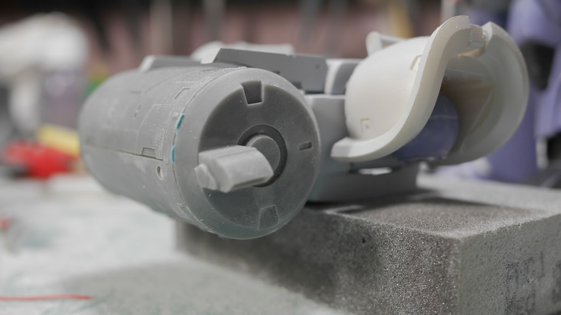
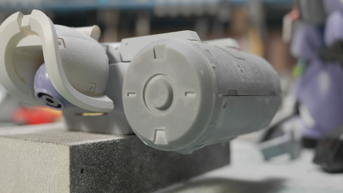
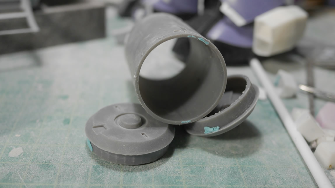
Again, as I get more familiar with the 3D design software and how my printer works, I’m more comfortable creating things. This time, I’m redoing the ammo drum. Here is the drum compared to what I built first. The fit with the attachment racks is perfect as the measurements of the original drum went into making the new and improved drum. Details such as the ammo port as well as all the surface scribed lines and raised surfaces. I did run into a problem when I raised the surface on the top and bottom. The lower attachment bar from the body to the ammo drum did not account for the small raised surface, so the fit was ruined. I had to redesign the ammo drum to remove the bottom raised surface and create an embedded surface instead.
Once that was done, the drum was reprinted and more test fit sessions to check and recheck things. Everything is looking pretty good here. I’m still debating on how I want to finalize the attachment of these pieces. I was thinking magnets. That will help make things transportable. But gluing everything down is always a good option.
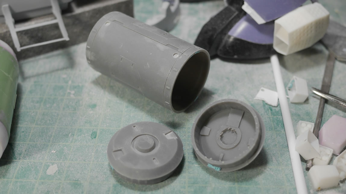
The drum was printed in 3 pieces. Resin is expensive, so it is ALWAYS recommended to design with hollows. The rear skirt is a design that is bad and not hollowed, so there is a great deal of wasted resin that makes the part way too heavy. I really should redesign that skirt piece, but I don’t want to; I’ll worry about this on the next project.
More parts are getting primer to check for defects and just to level out the colors. Primer makes me feel like I’m progressing. Another full test fit session to get back to looking at the big picture.
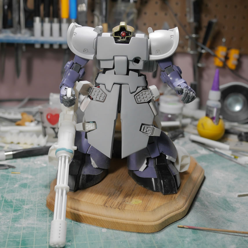
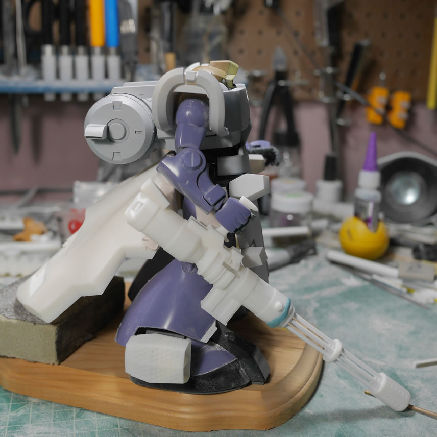
These test shots were taking at different points in the build. The front skirt details are glued, the operating of the missile pods was checked. And another print of the gun frame was redesigned slightly because the first print started to warp and the break. The walls were too thin. I went back to the Blender files and modified the design to thicken areas and just have a cleaner print using all the techniques I have learned since my first print of the frame.
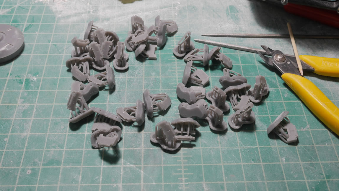
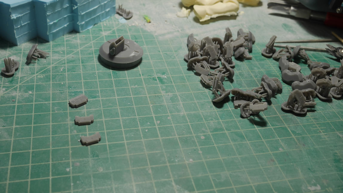
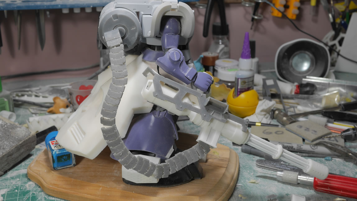
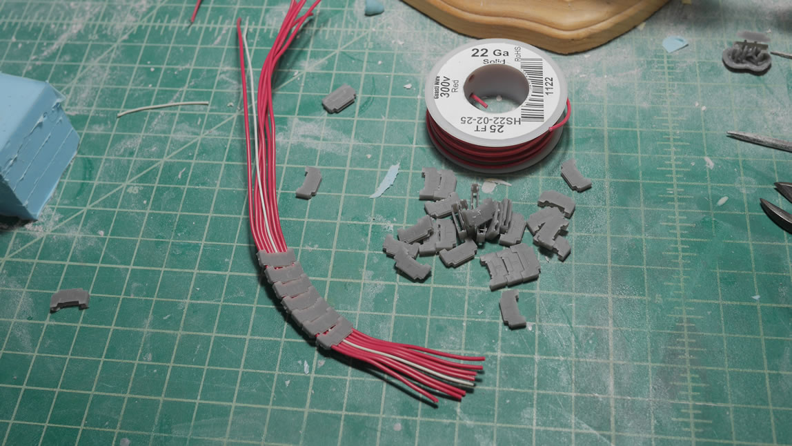
Next up, the ammo belt. There are a bunch of aftermarket ammo belts made of plastic and metal. Those belts don’t have the level of detail I want, so I designed three ammo belt pieces; the top attachment to the ammo drum, the middle link, and the end piece that attaches to the gun’s ammo port. I put a decent amount of detail into the design and some of the details don’t show up correctly since the print is so small. But I ended up hollowing and printing 30 middle links as well as one each of the front and end pieces. The front piece completely failed to print correctly, but this isn’t a big deal since that front piece was only meant to have an additional internal area as a wire stop. I designed the belt pieces to be interconnected with a wire so that I could flex and twist the belt as needed. The first test fit used one 24 gauge wire to hold things together for a quick, yet very flimsy test fit. I was really only checking for length and actual fit at the end points to the ammo drum and gun ports.
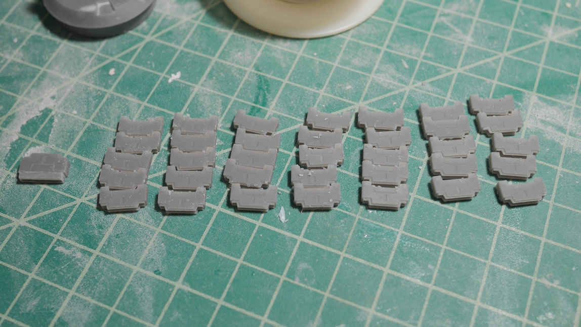
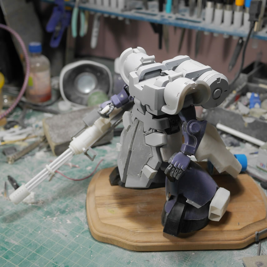
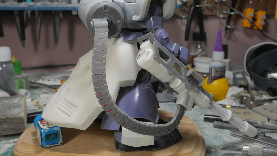
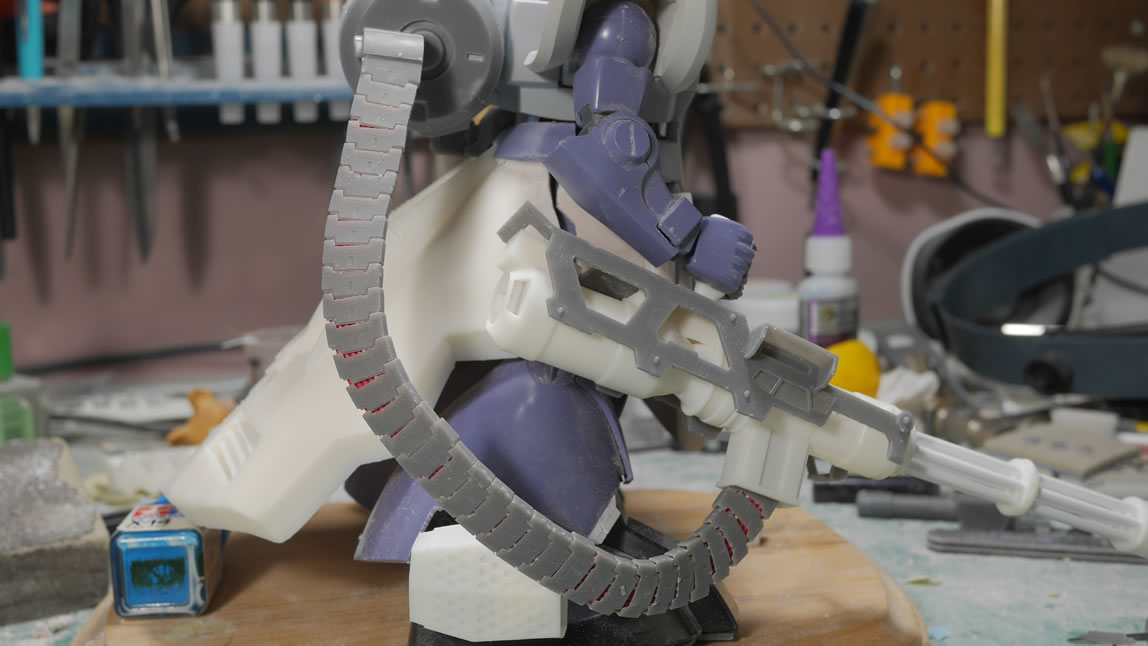
I ran out of the 24 gauge wire, so I went with 22 gauge and that worked better than the 24. It fit snugly so I do not need glue to hold the middle pieces in place and it retains flex and twist motion. I will glue to first and last end pieces. With the wire stacked into a flat belt; the ammo pieces are fished over the belted wires, the whole assembly is test fit with the drum and gun and everything looks pretty damn good. I just need to clean up the belt and get it primed.
The odds and ends are just build areas that didn’t really fit anywhere else in this post. The original design of the shoulders had a indention. This is attributed to my novice knowledge of the 3D design program and how to do rounded pieces like the shoulders. But it’s not really a showstopper as I can apply some light curing putty, sand, prime, and the shoulders are rounded with very little muss. Fixing things in post.
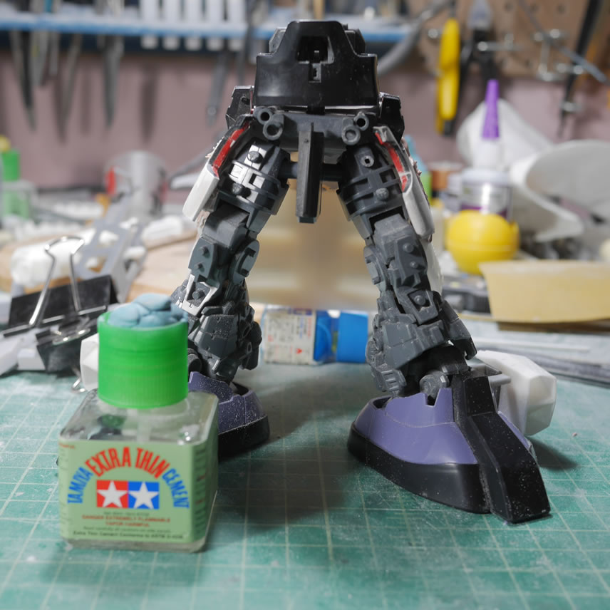
The legs saw some glue for the frame pieces. Since the rear skirt is quite heavy, I glued the legs which will help support the rear skirt. Once everything is done, the lower half of the kit will be completely fixed posed and glued together. I plan on keeping the mobility of the upper torso, but those plans may fall the pieces as the gun is also heavy even though it’s hollowed, but compared to the left side, it’s unbalanced, so the upper torso may also see a solid glue joint.
Hopefully the next update won’t take so long and I start getting things completed. There is a ton of build work, but I am getting closer to the fun paint stages.