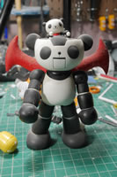
Our theme for this year’s SCGMC is the Bearguy, so I’m finally getting off my ass and starting up my Bearguy project. I think I may have bitten off more than I can chew at this time. Sometimes when inspiration hits you, it’s like being hit by a motorcycle speeding from your blind spot. You’re not expecting it at all, and *WHAM* the ideas just start flowing. I had been working on the Grim Reaper figure kit and I just had to pull a complete stop. The force is strong with this one and cannot be ignored. Little Miss Reaper joins the rest of the projects in various modes of development hell.
Way back when the first Bearguy came out, I had an idea of fitting the kit (1/144) inside an MG Acguy (1/100). The idea stems from the Panda-Z anime/toy that I picked up almost 20 years ago. The idea floated around for a while then just faded away into the back of my subconscious with the rest of the half-witted ideas I get. Then comes the Petit-Bearguys and the idea slightly resurfaced, but was quickly overruled by other projects in progress or of higher priority. Fast Forward to the end of last year when we announced our 2018 SCGMC Theme and add a few months before the true inspiration that really kickstarts the project.
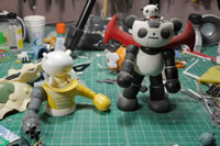
Aside from the Panda-Z, I’m also inspired by the giant Omni-droid from Incredibles. First step is to acquire the kits my imagination pulled together, so we have the 1/144 Kshatriya, the Bearguy San, an MG Ball, and a Petit-Bearguy. The arm of the MG Guntank was an afterthought so not really one of the full kits being used; I’ve already been cannibalizing that kit for several other projects; so what can one more do to hurt? The main pieces from the kits are quickly snapped together so I have a very rough idea of what I’m planning on bashing together.
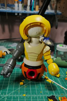
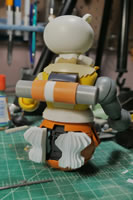
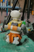
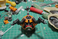
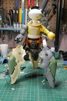
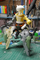
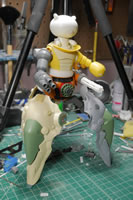
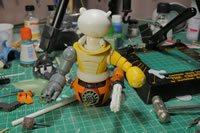
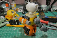
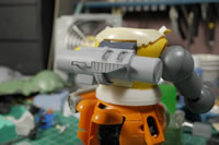
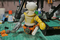
What I end up with is the Petit-Bearguy (PBG) as the driver of an upper torso of the Bear-Guy (BG) with a lower torso of the MG Ball, and the Kshatriya (K) binders as legs in a tripod configuration.
This project started near the end of March, and I’m only just now getting around to making a post because I actually have a fairly decent progress flow. So after the jump, this wall of text and pictures taken over the past month continues. A snide note, I used a bad option on my camera that pretty much ruined a good number of pictures. So the different resolution size are pictures from my camera phone and what pictures I was able to salvage.
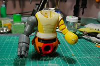
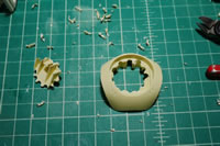
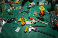
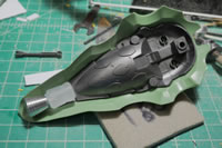
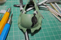
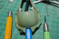
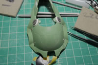
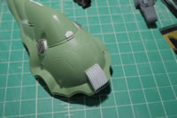
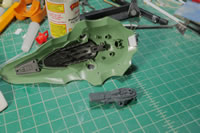
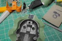
The first step is any kitbash project after the initial test fits is the destruction. Dremels, cutters, hobby knives and flying plastic everywhere is a really fun way to start a project. The torso of the BG is cut apart so that I have an area to combine with the Ball. The upper area is cleared so I can reconstruct the internal areas to create the beginnings of a cockpit. Some plastic plate is added to the bottom and new polycap joints are added to the left side torso and the bottom of the torso for new connection joints for the Guntank arm and the lower torso Ball.
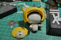
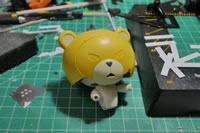
I typically work in a very stream of consciousness method. I have a rough plan or idea, but as I progress, the ideas will change and evolve as the project unfolds. Once such idea that quickly jumped into the forefront is the BG’s head. It seems fairly wasteful to not use the iconic BG head in this project. But how was I going to use this along with the PBG? Heh, I know, I’ll create a motorcycle helmet.
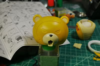
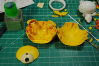
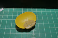
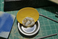
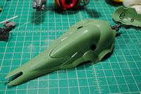
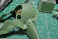
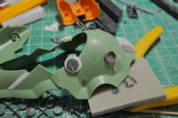
The first step here is to clear out the internal plastic structure to the BG head. The to main halves of the head are cleared and the faceplate is assembled. With everything cleared, I do a quick test fit over the PBG’s head to ensure not just a good fit; but that it actually fits over the PB’s head.
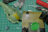
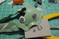
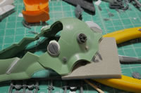
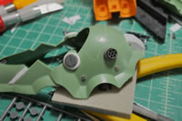
The main two bits of the head are good to go, so it’s time to focus on the face. The idea is that I will make a mold of the face and make a clear resin copy of the face. This will act as the helmet’s clear face piece. For this to work, I needed to glue the face pieces together and putty the hell out of the back side of the face since there are plastic structures that attach the face to the original head areas. Now, the structures in the main headpiece are gone now, there is no need for these. And once I make a clear copy, I don’t want to have these structures in the resin either as it would just look out of place. This whole area is puttied and sanded down.
Small pockets of bubbles and surface defects need to be fixed, so dissolved putty is used. While all these putties are curing, I’m working on other areas of the project; but for the sake of continuity and ease of following the project progression; I’m grouping the focus areas in this post. Another few quick test fits to make sure the putty isn’t blocking anything with the PBG head inserted.
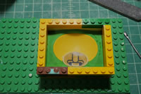
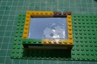
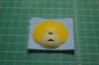
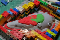
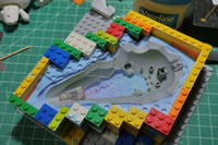
With the surface sanded and ready for paint. I don’t actually go to paint since I can eyeball the look and just go right into making the mold. A bounding box of legos is built and the bottom layer is filled with playdough. The face side is pushed into the playdough and the first half of the mold is made with silicone RTV. Once cured, the box is broken down and the playdough washed off and it is ready for the second half of the mold.
Once the two halves of the mold are made, I can pour clear resin and stat making clear face molds. Once cured, I get a quick test fit and start to see how this will come together.
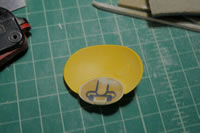
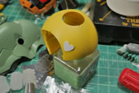
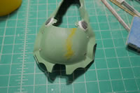
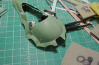
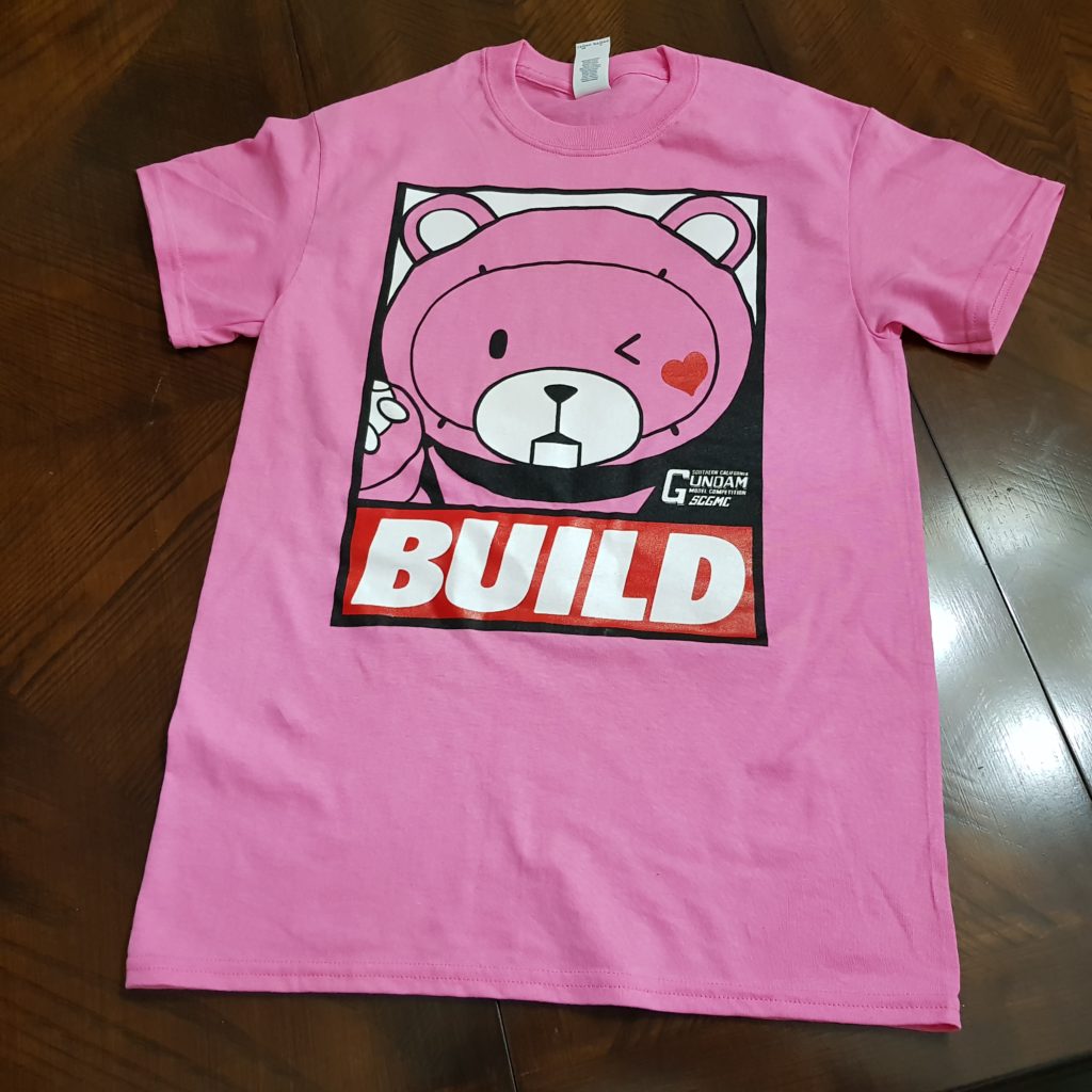
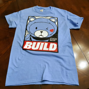
A few more test fits and some surface prep for the main head piece get it ready for paint. I added a little heart plastic detail that I will go into more depth on how that was created later in this post. The little heart detail is a nod to our BearGuy shirt design. Again, I’m working on several areas of the project at the same time while other areas are curing. The head piece is primed to check for surface defects and then everything is painted.
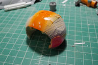
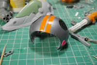
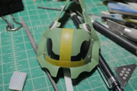
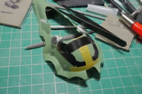
The main helmet is painted with Tamiya TS-100 which I used for my Mercedes build. I masked and painted an orange stripe as well as masked and painted the heart with Finisher’s lumi-pink.
The eyes of the face are painted with clear red. The back side of the face is painted with clear gloss. Then the whole head is assembled with the face piece glued to the main head using aircraft canopy glue. Once everything is set, the whole helmet is sprayed with copious amounts of clear gloss to get that shiny motorcycle helmet look and feel. I have foam inserts glued to the inside of the helmet to provide some cushioning when it is on PBG’s head. It also works to center the helmet over PBG’s head. At least I have something finished in the first progress post for the project.
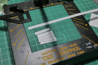
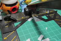
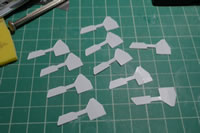
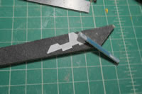
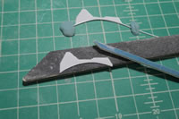
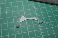
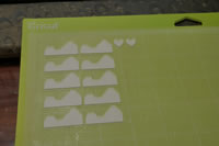
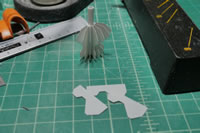
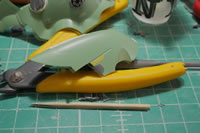
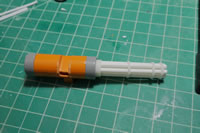
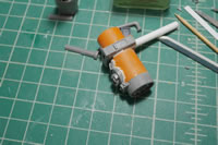
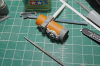
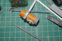
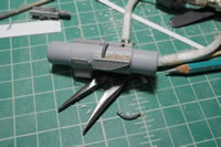
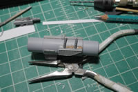
Below is the first attempt at making a shaped heatsink. So this was a complete failure. But it works to illustrate how to do this if you have the patience. Also, while I was working on this, the original plan for where I was going to place the heatsink changed. But the idea here is to use the chopper and cut plastic pieces out and glue them together to create each individual fin of the heatsink.
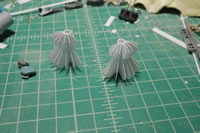
Once the glue cures, I can start sanding down the connection points and then start gluing the pieces together to create the heatsink. The original plan was to place the sink over the curved surface of the binder, so each individual fin was cut and a separation piece of plastic is glued along the bottom to build the sink.
My impatience and the practical placement went out the window and I sort of backed away from this idea.
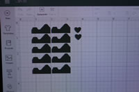
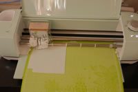
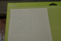
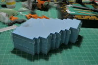
That is until I remembered that I have a cricut cutting machine. I designed a fin piece and made copies in the cricut designer tool. Then placed a sheet of 10mm thick plastic onto the cutting template and ran the machine. This is where I made 10mm heart shapes that I glued to the motorcycle helmet. Theses fin pieces were perfectly uniform.
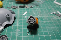
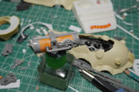
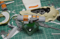
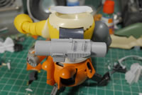
Using the same method as earlier, I created a heatsink for the binder and for the back of the Ball where the thruster engines exist. This worked out much better than the first attempt and I used a plastic tube as the center structure and created a curved vent where for the binder, I used a flat piece and created a flat heatsink. A little note about the ball, I oriented the Ball upside down for its use in my project because things just worked out better with it in that orientation so there is going to be some reworking of other things so that it all sorta normals out.
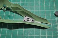
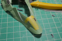
Onward to the binders. I sat for a while thinking about how I wanted to approach the binders. I ended up trimming the front fork off and cutting the tip off the inside frame piece. The idea is that I will be attaching a resin cylindar detail piece from the resin Ore Gun and attach a large thruster bell here. This will sorta be the “foot” thruster. Below is a quick mock up.
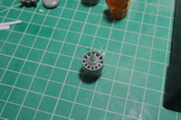
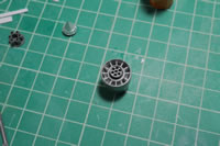
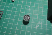
I went to Japan in March of last year so I went and stocked up on a bunch of koto and wave detail bits from the Yellow Submarine shop. I pulled some round detail bits and took pictures of different configurations before settling on the minus mold detail. It was fun to get a good look at all the possibilities. Here I have the original design and the design I picked.
Below are the other options. For the sake of argument, I posted the variants on FB to see what kind of response. The two top choices was the turbine detail and the minus mold detail, turbine being the first. I had posted after I already glued the minus molds in place, so it was interesting to see how my choice fared against the general populous. I was pretty damn close.
Next up is to do some scribing. I used the cricut cutting machine to draw out a design and cut some masking tape and vinyl tape to lay out a design for the scribing. And once I finished, I realized that the symmetry was completely off. I also realized that the location of the scribing didn’t look good either.
It’s just plastic, so out comes the putty and after sanding, the surface is ready for another go at scribing. I printed more templates, but this time took some extra care with laying down the templates by using some tamiya masking tape as guides. This really helped out the symmetry. Some dyno tape is also employed for some extra lines I didn’t cover in the template design.
I think this looks better than the originally scribed lines. And they’re much more symmetrical.
I made a few designs for heat sinks, and was also testing the cricut machine. This time I used a .2mm thick piece of plastic sheet and made some cuts. Then glued together the parts as described above to create another heat sink. This was then glued onto the top of the binder piece filling in the gap at the top. I wanted some detail in the back, so I found a leg piece in my box of parts and cut it out to size and just glued that to the back. As simple as that, I have my detail for the back of the heat sink.
The scribed curve area just begs for some detail, so more koto and wave detail bits and I now have dual gats on the top of the binder. I also took the time to decide on what I wanted as the detail bit as well. Context is key. Since the binders are not really binders but legs, the detail bits sort of work.
I added more koto parts to the top piece of the binder (tripod leg), as well as some vents to the bottom of the tripod leg.
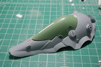
Detailing for the leg is done and I have a comparison with the out of box binder. A quick spray of primer shows the mistakes that need to be fixed.
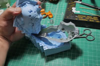
Since I need 3 legs in total, I figured I’d just make one modification and then mold it and make copies. This sorta works. I end up using a huge amount of silicone. So the value vs work of just building the three binders is arguable. I think I made the better choice. I did two halves for the mold similar to the bg face. The playdough is used to fill in negative spaces so I don’t use that much silicone. The second pour of silicone also had old cured molds added to help offset the amount of fresh silicone required. Silicone sticks very well to itself so old mold can be cut up and used as filler. Once done, the original is removed and the mold is prepped for the first resin pour.
The first pour is always a shit show. It usually works to help clean out the mold and also works to test how to actually pour and work with the resin in this mold. I made three more pours before I got 2 good enough copies. There is a huge amount of cleanup and fixing, but I think it beats the hell out of trying to bash/scratch identical pieces.
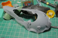
The legs done, I can finally do a real mock up of my project. The first thing I need to do is to glue in the connecting joint pieces to the bottom (actual top of the kit) of the Ball. Reason I used this orientation is that the bottom of the MG Ball works as a perfect connection joint to the BG torso. The top of the Ball works very well because it’s got holes and a structure I can use for the binder’s connecting joints. Those are glued into place and left to set.
Once the connecting joints are set, I plug in the legs and my BG has legs. I finally have a more realistic mockup of the project design a month into building.
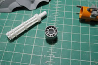
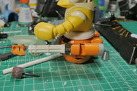
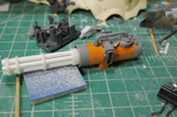
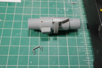
I need a break for working on the binder/legs and I did not want to spend the rest of the weekend cleaning up and fixing the resin. Time to build another gatling gun. Using some styrene tubes, some 3D printed frames from when I built the Gusion’s Gat, and one of the Ball’s main arm pod assembly pieces; I start to put together a rough weapon. The front and back of the gat body is capped off with more bits from the Ball. I cut some plastic pieces and glued them inside the space between the two circular areas on this part. Originally, a rubber piece fits into here and the rest of the Ball’s arms body extends from here. The pieces of styrene work to make the part look more like a turbine. The center of the part needs some details so Again, I have some choices. One side is for the back end of the weapon’s body and the other side is where the barrel connects.
This time, for the back of the weapon, I picked the turbine detail as it goes very well with the outer turbine look.
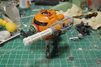
Here are some quick mock ups of the base weapon and how it fits in the grand scheme of the BG. Side cannon so to speak.
The cannon is fairly plain so time to start looking for detail bits. The Ball has some amazing detailing in all areas of the kit. So it’s easy to find something and just cut it up and use it all over the place. This version of the Ball has the twin cannons as well as the main cannon. I used one of the twin cannons and just cut it up and used sticky tack to get a general look and feel for things. The side piece of the ball where there’s a detail clear piece is glued in here as one of the main detail bits. One of the tube bars from the Ball kit fits perfectly coming out of the side part and just adding a wave circle detail completes the look. The engine detailing on the twin cannons is also cut up and added as engine details for the gat body too, running perpendicular to the Ball’s side bit. A small venier at the bottom completes the mockup.
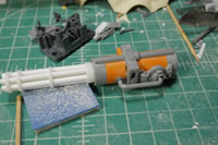
With everything mocked and approved, we go to gluing and filling. There is an awful amount of filling that happens in kitbashing. Styrene is your best friend. Glue melts and welds the pieces into place. Once set, a quick sand to rough up and shape the gap areas to prepare the surface for some putty work. After the excess putty is cured and sanded.
The initial surface prep is complete and it’s ready for the first layer if primer.
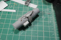
Next up, the fuel tank. The other side of the Ball’s arm pod doesn’t go to waste. Here I quickly put together a fuel tank and filled in the rectangular cavity with stacks of styrene strips and then sanded it down. The two ends of the Ball’s arm bits are used as the two ends for the fuel tank. But just like the gatling gun body, it’s boring in this current state.
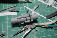
Cutting up more bits and pieces from the Ball kit, I start adding details here and there. The gear detail from the big cannon on the original Ball is cut and used here. A small tube detail is added by drawing out some straight lines and making the right measurements and a few drilled out holes and the tube detail is inserted. One of the pieces has two male pegs that I cut off so there were some holes to fill. Instead of filling, I found some left over Zaku/Gouf head cables and trimmed them up and added them as connection tube details between the top piece of Ball twin cannon gun barrel haves and the bottom vent detail with the peg holes.
As glue to the add on pieces dry, the areas are sanded and more details are added so that there is a bit of transition between some of the added details. The tubes just sticking out of the middle vent piece just doesn’t make much sense, so some koto round detail bits are drilled out and added into the area as a transition piece. Once all the initial sanding is done, another layer of primer is sprayed to check for flaws. There are definitely flaws, and the primer really shows the problem areas nicely. So next up will be more clean up work, but the build for the fuel tank is done.
Small details here and there to further dissociate this from being an MG Ball. It will still definitely look like a lower MG Ball torso, but hopefully the details will help transform this more. I found some round bits from the Kshatriya so another koto gat detail piece is added here.
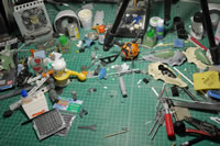
The workshop is a mess but I’m having a pretty damn good time building gunpla. It’s been a while since I wasn’t inspired to do anything since SCGMC. Hell, the MG Hazel is still only about 95% done since the shields I made are still in various stages of paint. It sits with the rest of the half done projects as well as the newest member, Grim-Chica. So hopefully the drive to work on this kit continues to keep it from joining that party of partial builds.
Shameless plug!!! Again, this is a Bear Guy build and as our theme this year for SCGMC is the Bear Guy. It’s not about how elaborate a Bear Guy kit you build, but how many Bear Guy shirts you buy!!! Get your shirts while we still have some in stock! We have one in Pink and one in Blue. Wear them proudly!
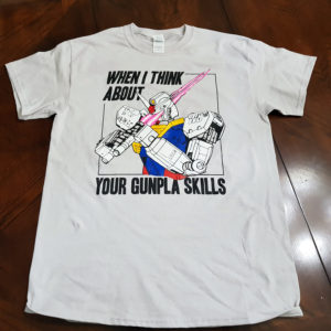
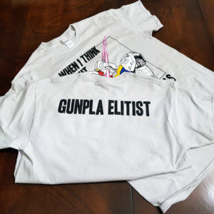
We also have another new shirt we have up for sale now is based off the chess piece designed by our own Bhop: the Gunpla Elitist T-Shirt. Get your elitist shirt while supplies last and wear them proudly at any gunpla event you attend!
This also helps us bring you guys SCGMC every year, so every dollar spent goes right back into making the competition bigger and better! [/end plug]
