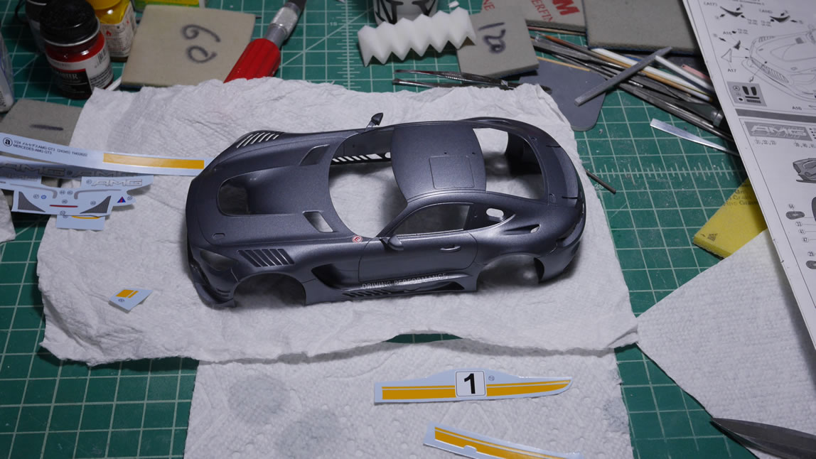
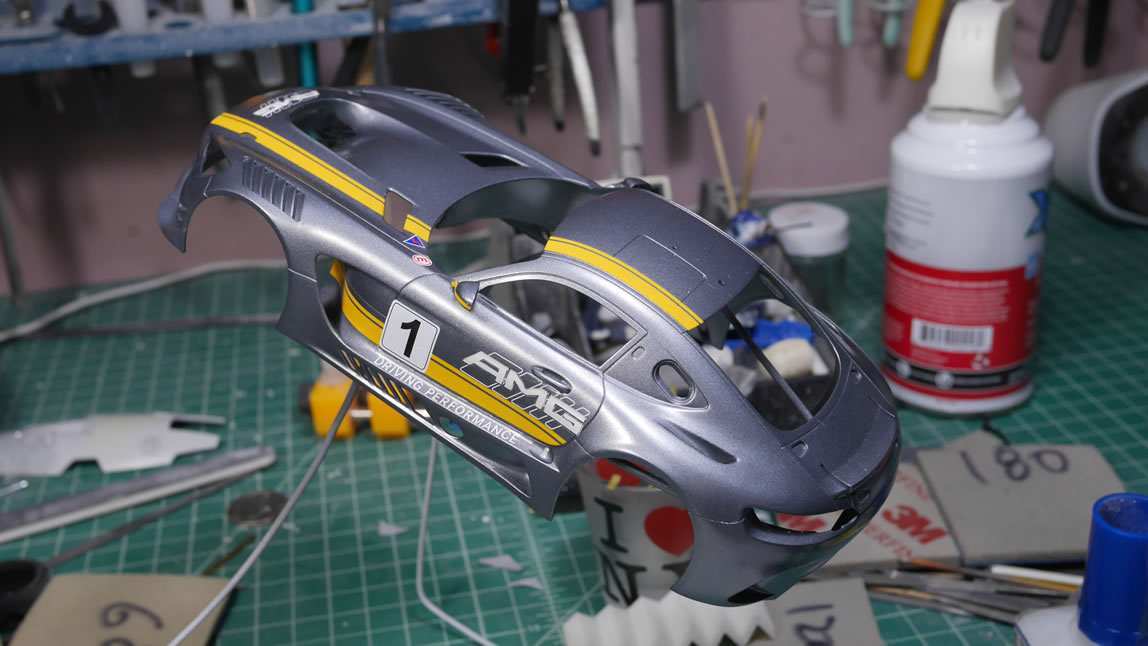
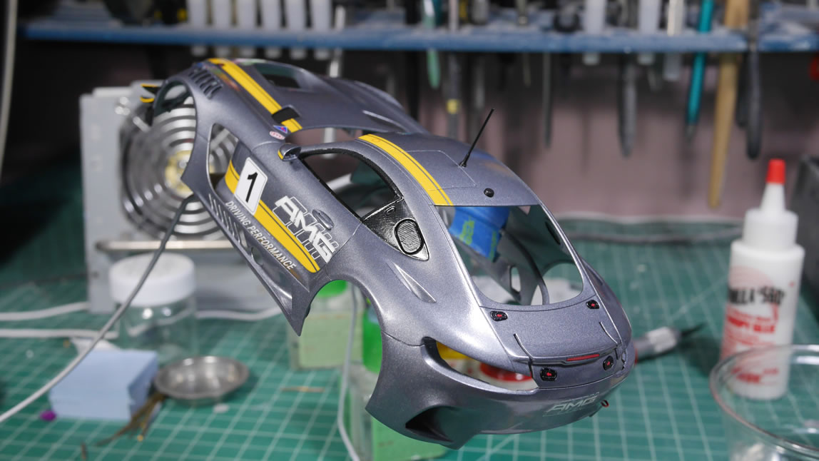
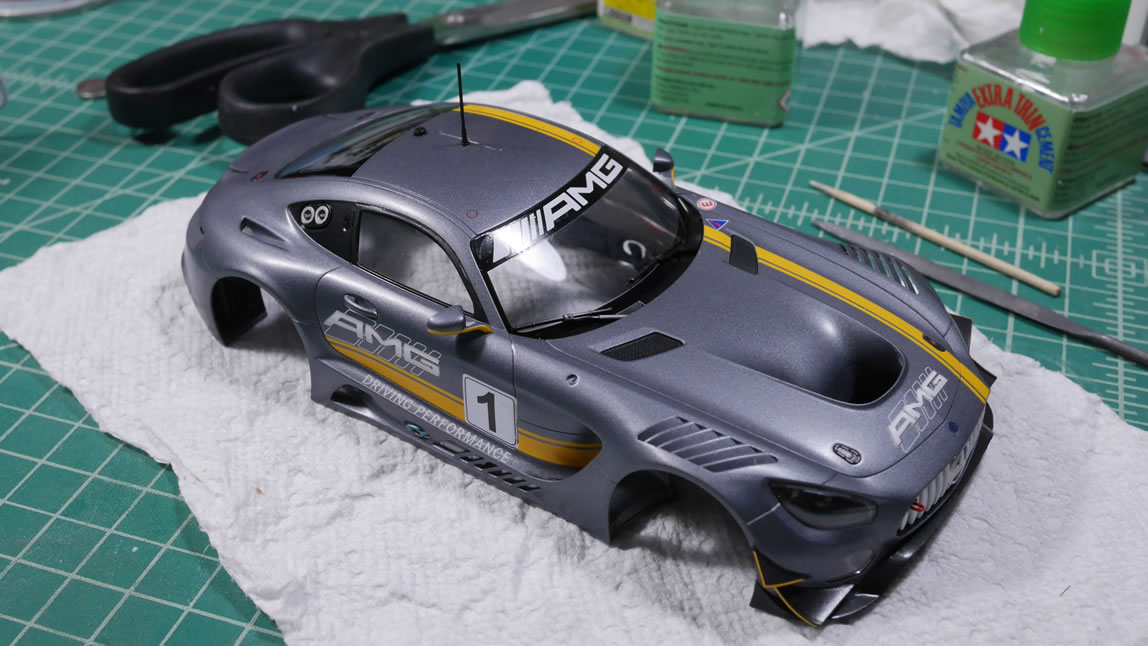
The body paint is done, or so I had thought.. so on to the fun decal work. The paint for the body is tamiya bright gun metal which is a semi gloss finish. That means I need to clear coat the crap out of the body before getting to the decal stage. I did the gloss coat in the last update so on to decals. This car isn’t too bad for decals, it’s not one of those itasha style cars, but it is a GT car. Luckily, it still isn’t as decal intensive as most race cars. The process is slow, and with how I worked, it should have been even slower.
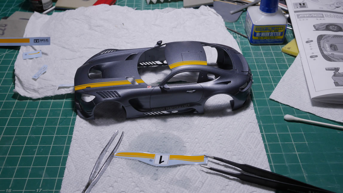
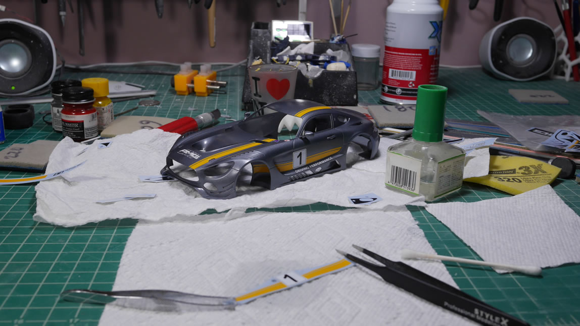
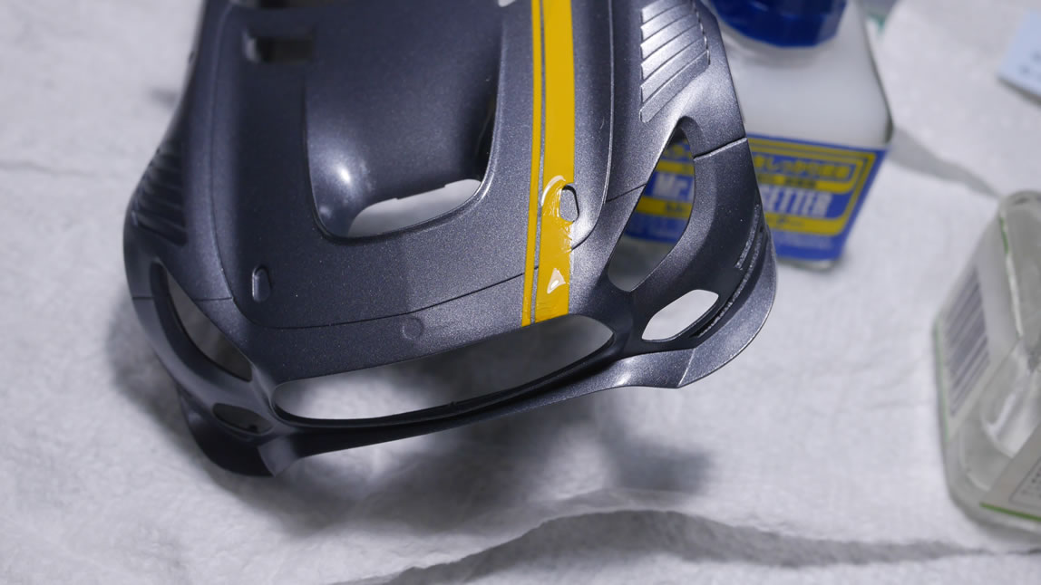
Once the decals are on the surface, I need to let them dry out completely. Then on goes the decal softening solution. This stuff will help melt the decals into the panel lines and get the decals to curve along the surface as if they were painted. The decal softening solution will wrinkle the decal in the process. It is very important to acknowledge this and leave it the hell alone to dry on its own. It will flatten out. Caveat, it will flatten out if the surface is flat and upright so that the decal and the softening solution don’t pool in any specific direction but flat onto the surface. The spoiler has 3 decals on three sides, and doing the softening solution process really should have taken 3 days – one for each side. But in my haste, I rushed it and did it at the same time. This pooled and shifted the decal so when it wrinkled, it stayed wrinkled. Huge lesson learned here. Paint and surface prep you can mess up on all day long. Those are easy fixes; decals unless you have a bunch of spare copies, is a one shot deal.
More after the jump.
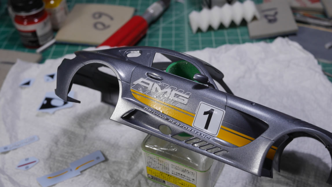
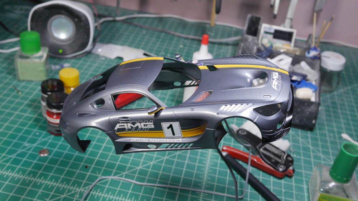
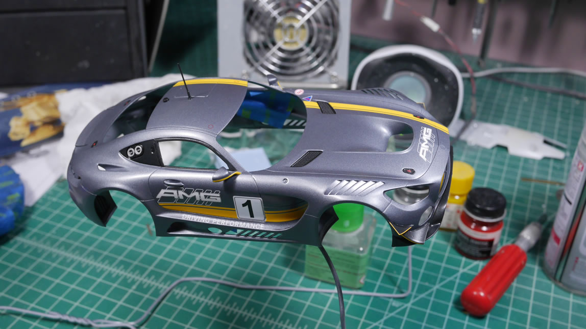
Most of the decals are done and the softening solution has cured for a full day. Another layer of clear gloss to seal in the decals as well as help hide any residual decal edges that didn’t get fixed with the softening solution. So the decals are done? Not nearly.
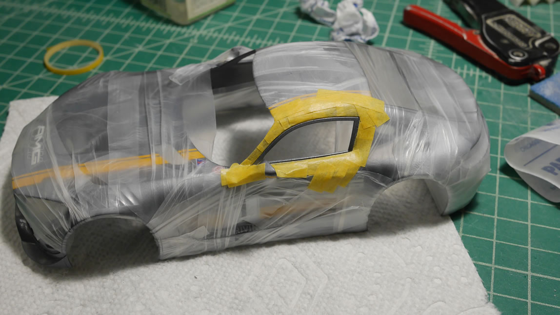
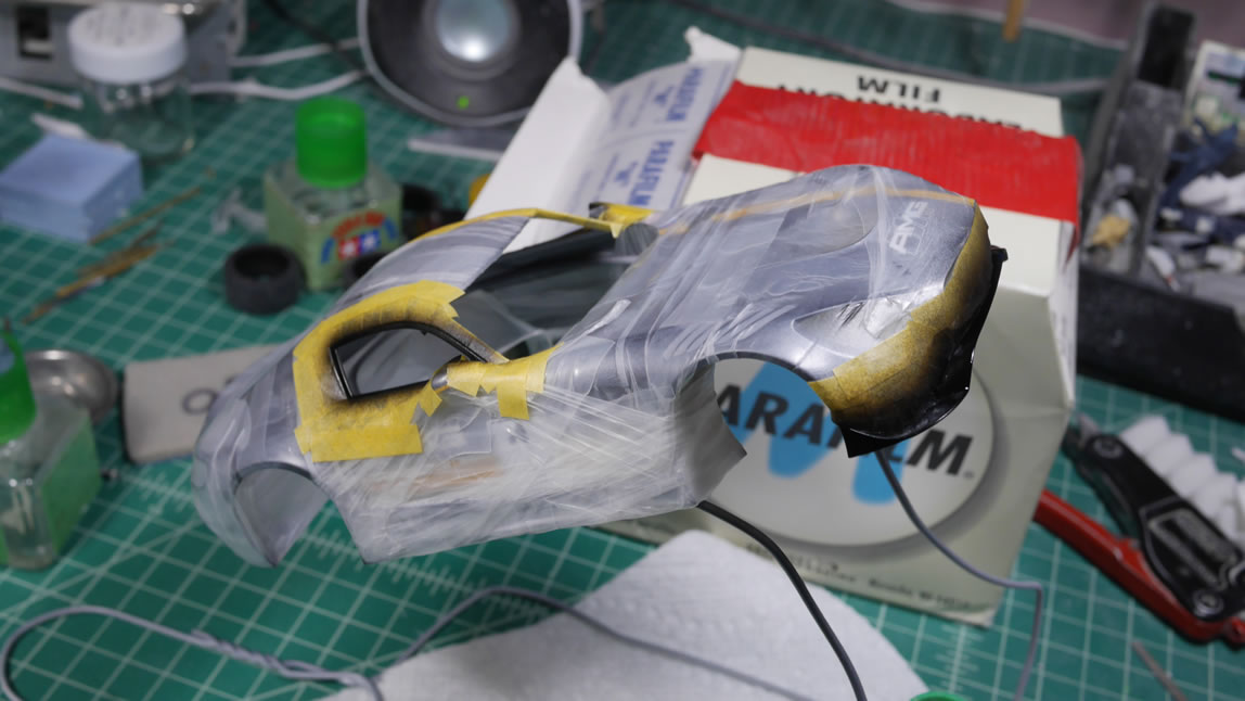
I finish most of the decals for the body and run into the carbon fiber decals. Applying these on the bright gun metal color surface wasn’t going to work. I had missed the step that told me to paint these areas the semi gloss black. Oops. The whole body is masked off and the semi gloss is painted onto the window frames.
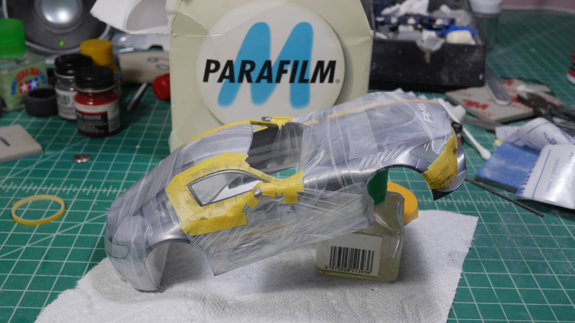
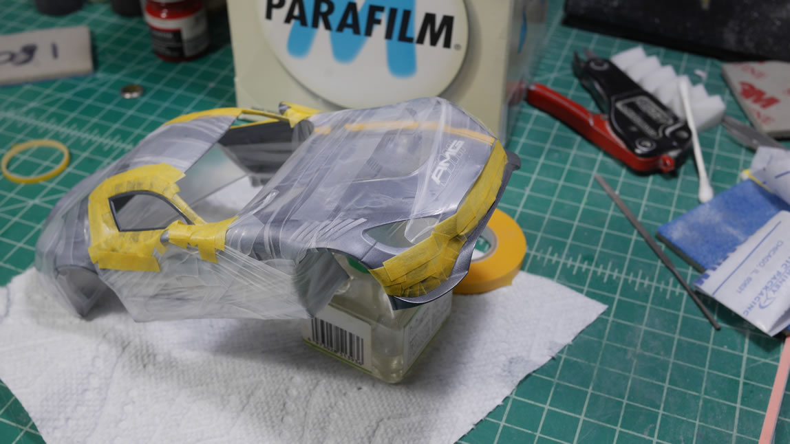
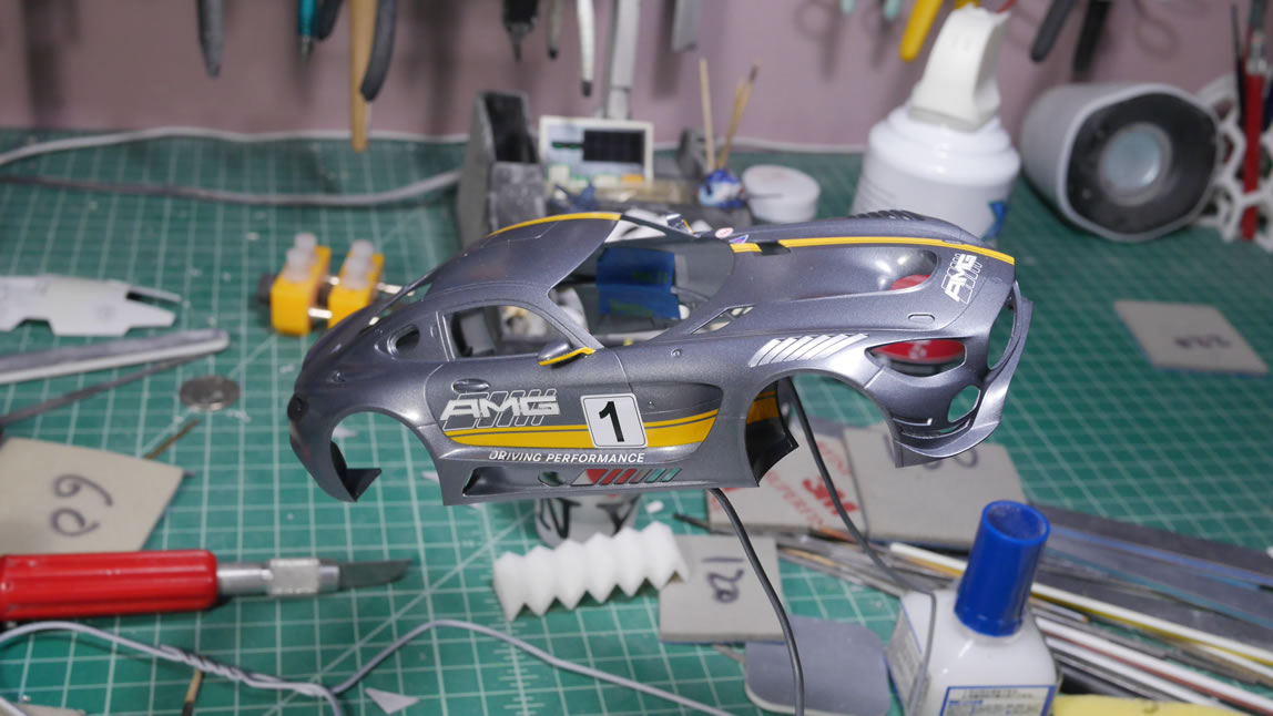
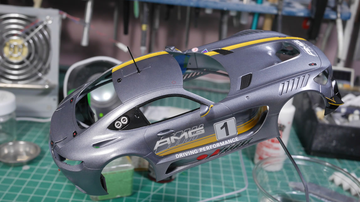
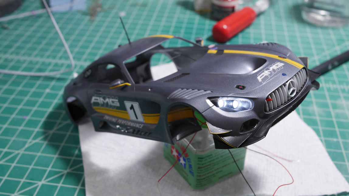
Painted and unmasked. Note that I also missed painting the back area behind the windows. I needed to remask and paint this section later too. The small body pieces are getting glued onto the car now.
The back of the side windows area are masked and painted and decaled. Everything gets another layer of gloss.
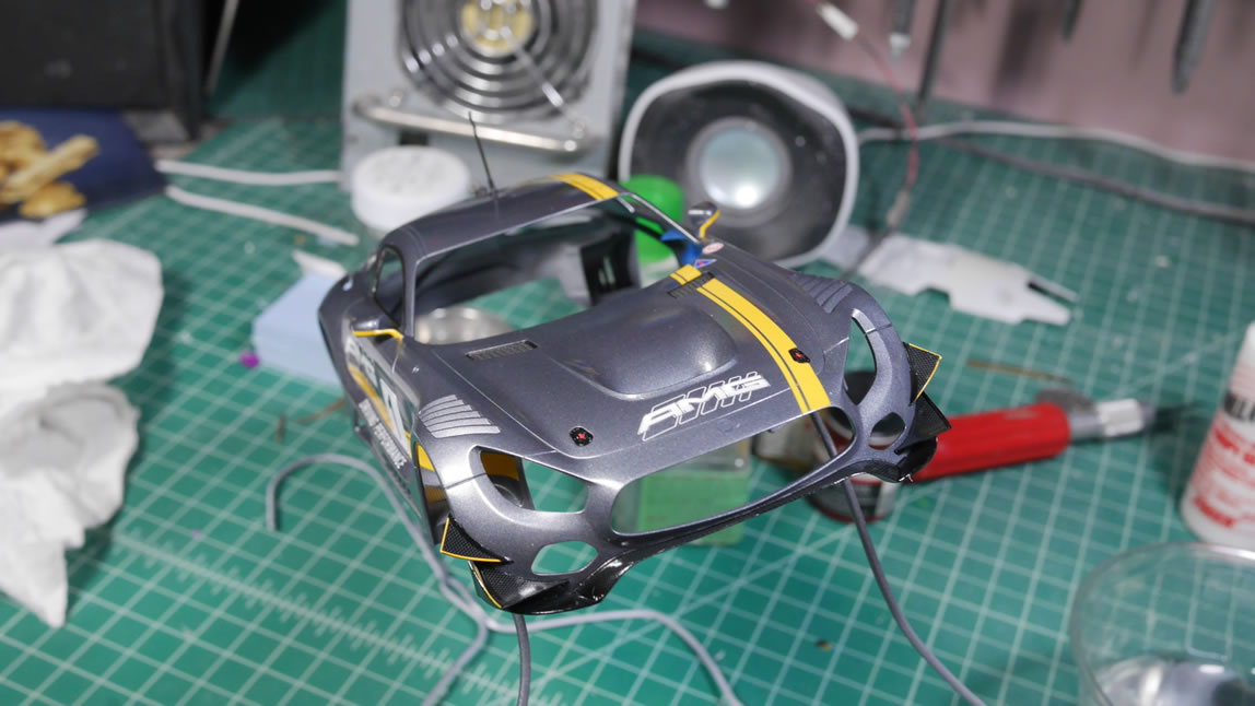
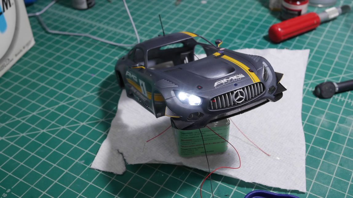
Front grill and under grill bits are glued. It’s starting to come together. I really need to slow down, not speed up. Impatience is going to ruin everything.
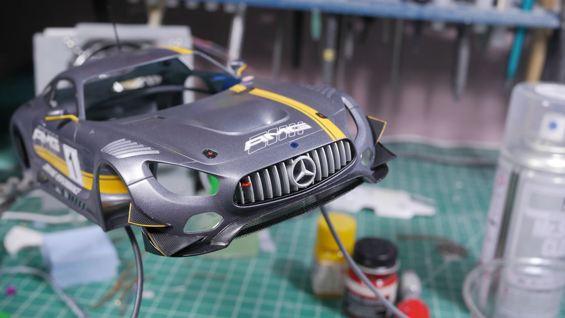
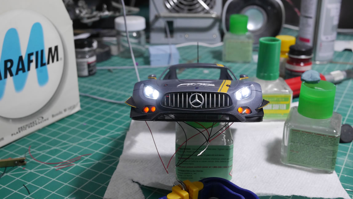
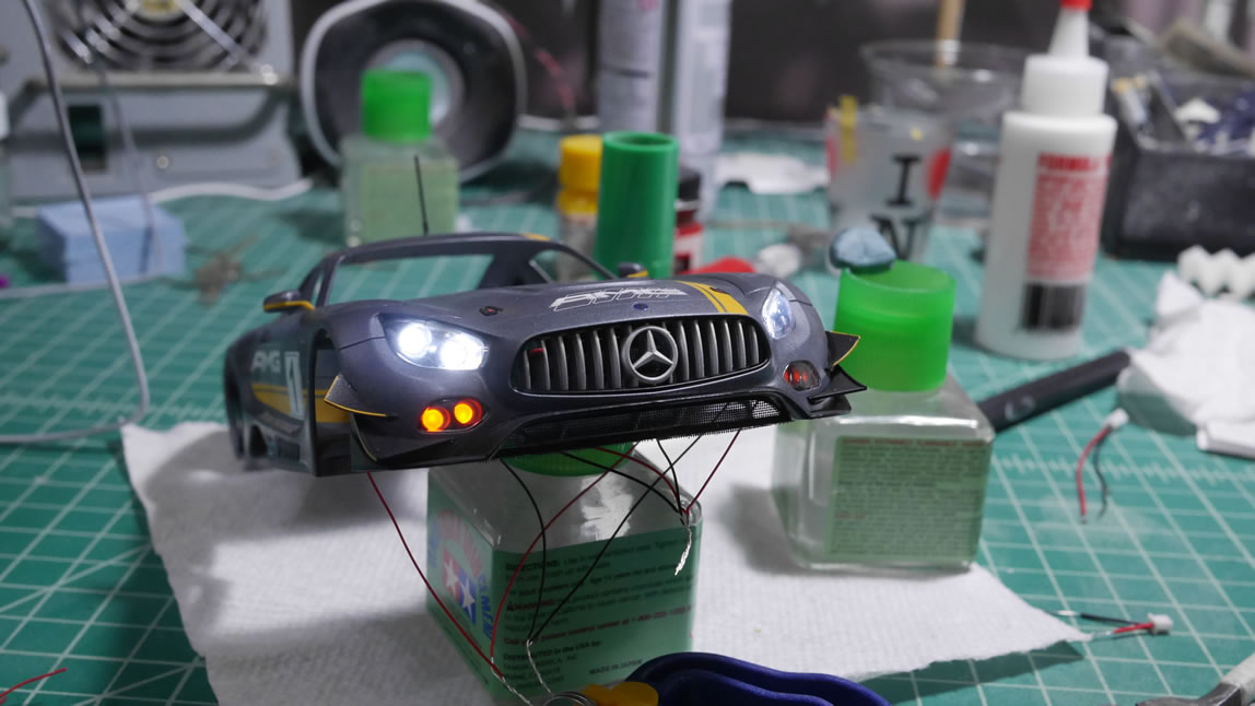
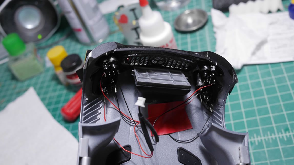
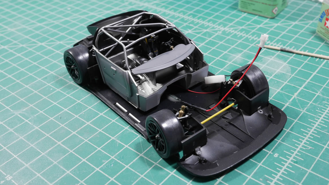
I get over zealous and start gluing the headlights and fogs into place. In my haste, I forgot to clean up the back of the headlight lenses before gluing in the main headlight housing. I wanted to get the lights tested. There are 4 assemblies with 2 LEDs in each assembly. These two LED arrays are already wired in parallel to one another so each of these 4 assemblies has 2 wires coming from it, a positive and negative. Each assembly is glued and tested. Everything is working, so the body is left for the glue to set up over night before continuing.
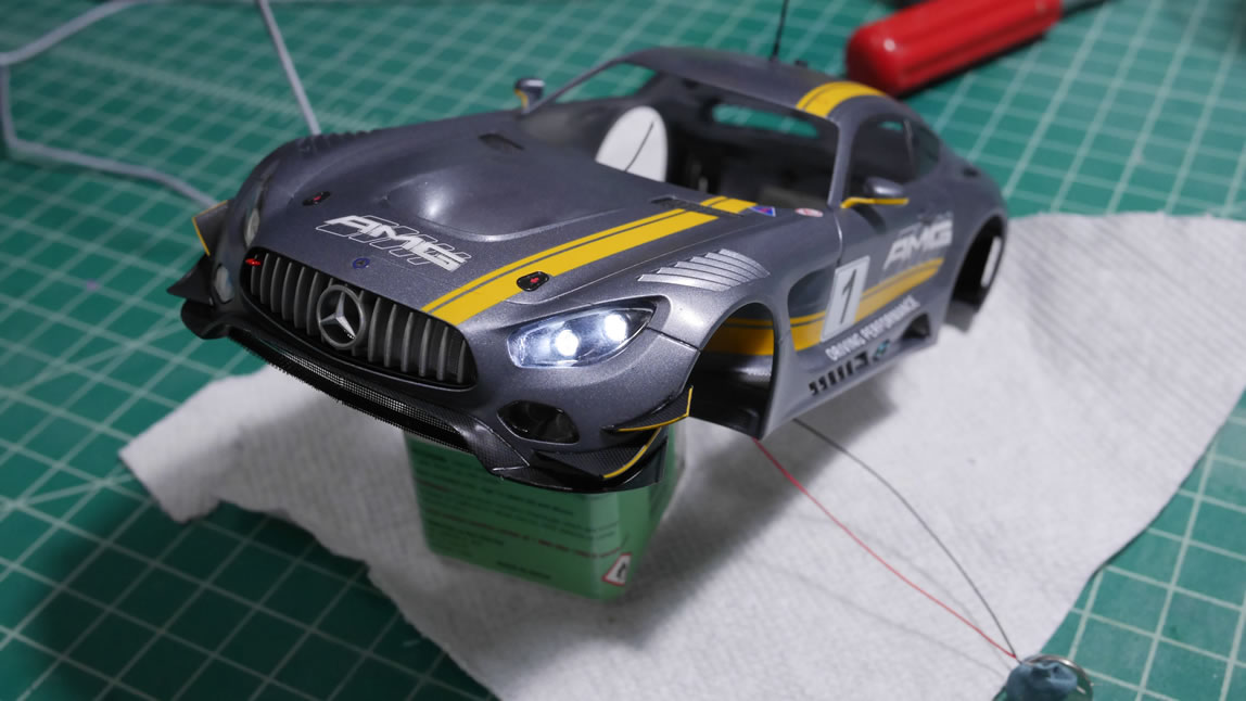
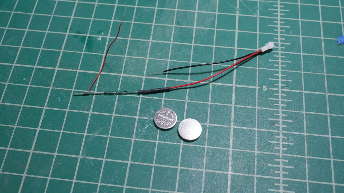
The glue has set and I can continue to work the wires. Since I’m using different colored LEDs, I cannot just wire everything in parallel and have it all work. The lower drawing LEDs will get power over the higher – yellows will be on while the white is off if wired in parallel. This means I need to wire this in series. This also means that my power source has to be greater than a single 3V lithium button battery. I needed to draw this out on paper to fully visualize and get everything to work correctly. Since the lights are in pairs, I can wire the like colors in parallel then wire them together in series. I start with the positive end for the white LEDs. Those are wired together and are my positive wire. The negative wires for the whites are bundled with the positive leads for the yellow LEDs. This continues the series connection from the negative white to positive yellow. The negative yellow leads are wired together and will be the outbound negative wire. When all is said and done, I have the positive end to the positive end of the white, connecting the negative of the white to the positive of the yellow, then the negative of the yellow out. I end up with two wires and I connect that to a small 2 lead JST connector. A quick test with two CR1220 batteries stacked together to get 6 volts lights up everything. The wiring for the main body is done and taped to the underside of hood to hide the wires.
On to the chassis side. I created another wiring harness that comprises the switch, battery, and connector. The switch is a small reed switch that will allow the whole system to activate with a magnet. The battery holder is a simple 3D design and printed to clamp two CR1220 3V batteries and the positive and negative ends out to the switch and then on to the female JST connector.
Windows are glued into place and also the final part, the shopping cart handle, is glued to the car. The body is now ready. Sort of.
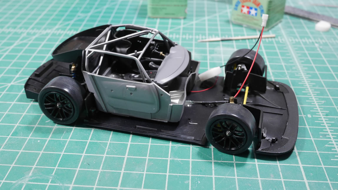
The wiring harness with the switch is glued to the chassis. In test fitings, the added LEDs created some fit problems. I had trimmed the LED leads down as much as possible, but there was still a few millimeters of spacing that was preventing the body to chassis alignment. This also throws off the wheels. So the the front ends of the front wheel wells were grinded down a bit to thin that wall and create the necessary space for the lighting mod. Once that was resolved, the JST connectors are mated and the body and chassis are combined and that’s all she wrote.
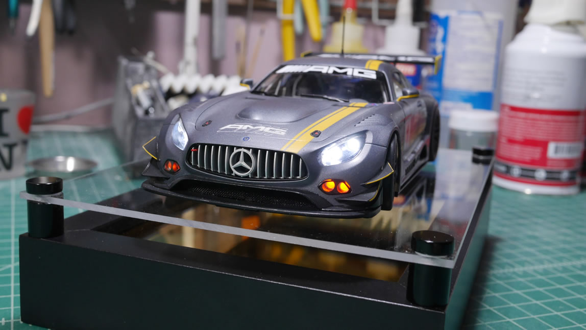
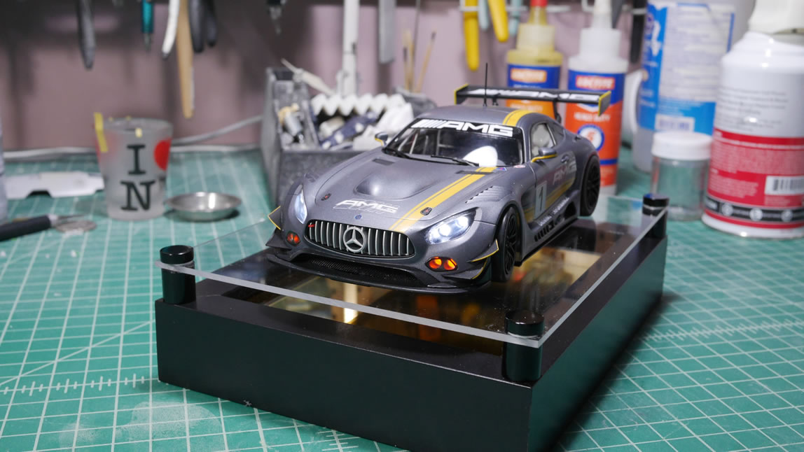
Here’s a quick video showing the completed car and how the lights work.