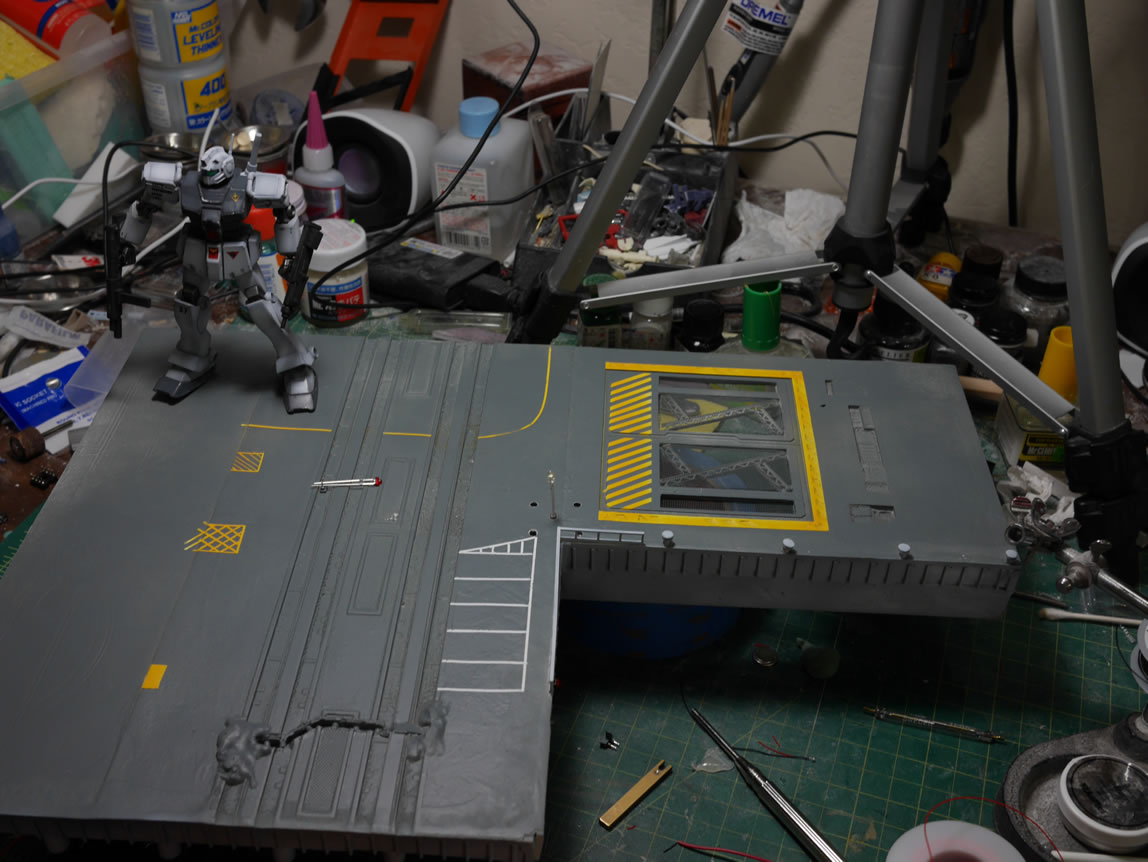
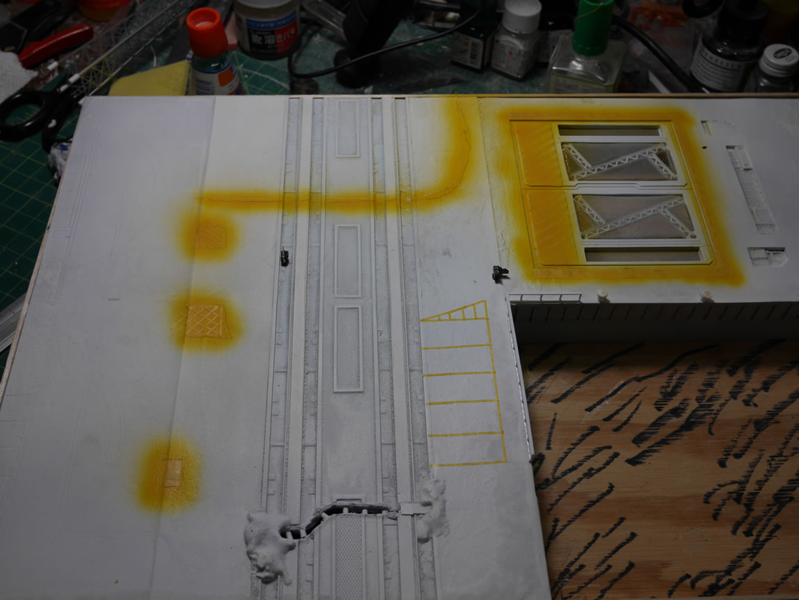
Work on the diorama continues. Some areas slow down a bit as a good deal of work is not overly visual, at least from a progressive standpoint. Getting tired of just the white base coated base, I masked off a small parking spot, then painted on some yellow. Then masked that off and sprayed a light grey over everything. I failed to snap pictures of the masked off base and the results after I painted. With a project this size, I end up juggling things so that while one area sits and cures, I can focus on another area; but also keep from working on too many separate pieces so that it becomes overwhelming. I learned this lesson last year around this time when I really wanted to push this sucker out. I simply got overwhelmed and the interest to even work on it died. I currently have an outline written out for this project. This is the first time I actually wrote something out; the help with organization is amazing, and I can see that certain things should be done before other things. And with areas of the project are completed, I can cross those off as being done and keep the focus. Currently, I’ve finished the containers, the GM’s, and recently, the base light that I had trouble figuring out the last time around. That’s at least 40% of the players for the diorama completed.
As the title says, I had to do some wiring work. I previously wired the base up; but as the build progressed, things changed and the wiring scheme must also evolve. I have a video of the re-wiring process after the jump!
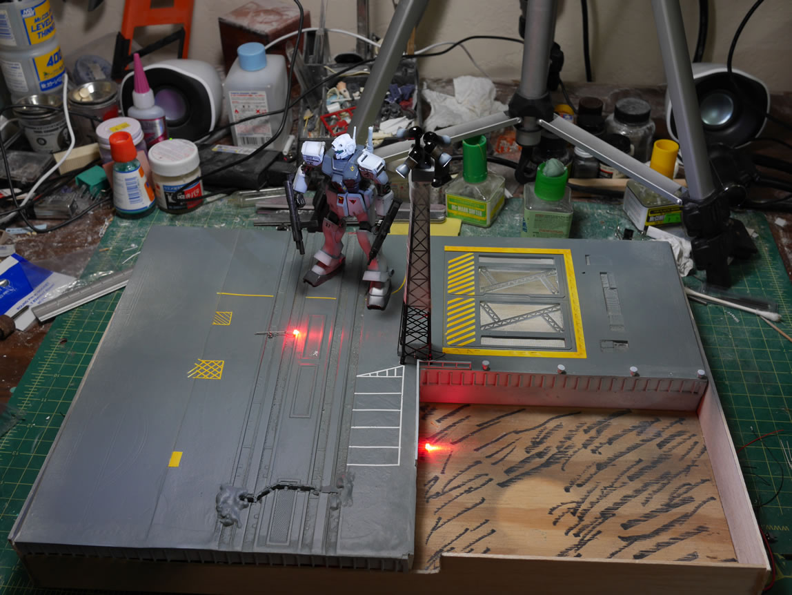
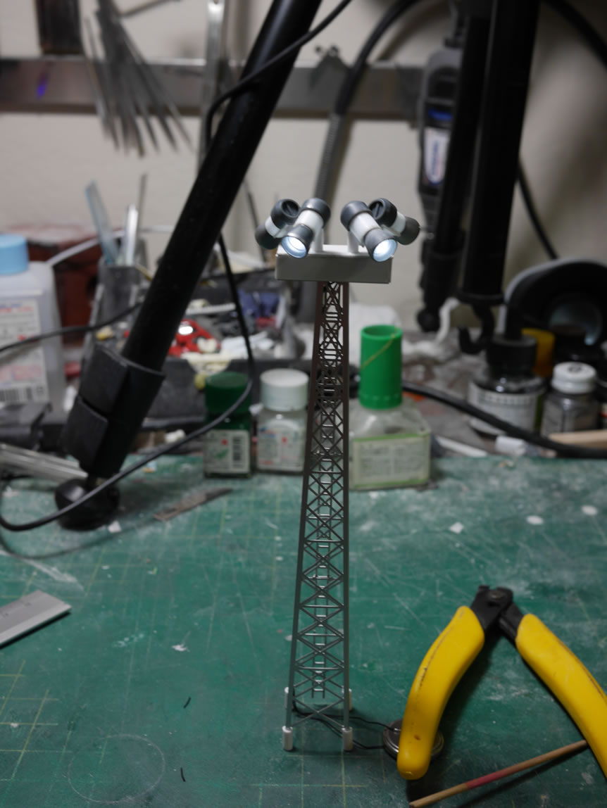
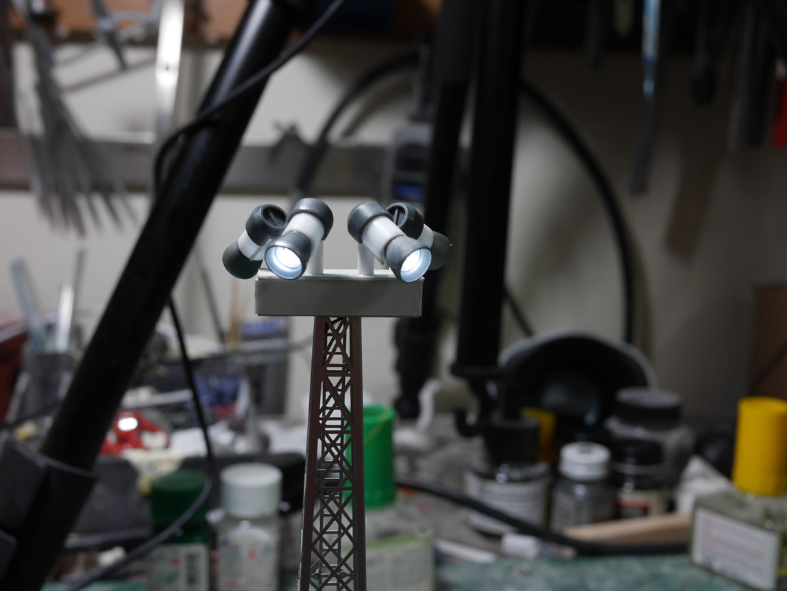
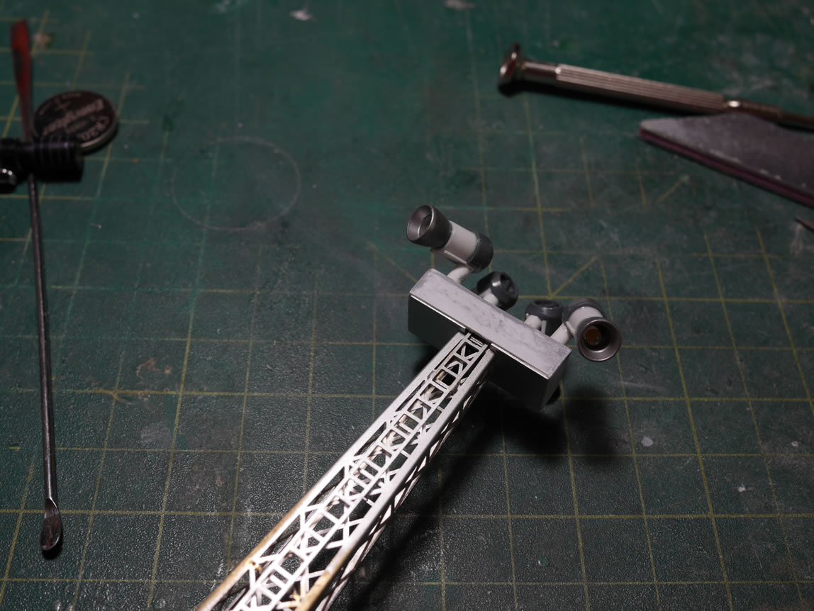
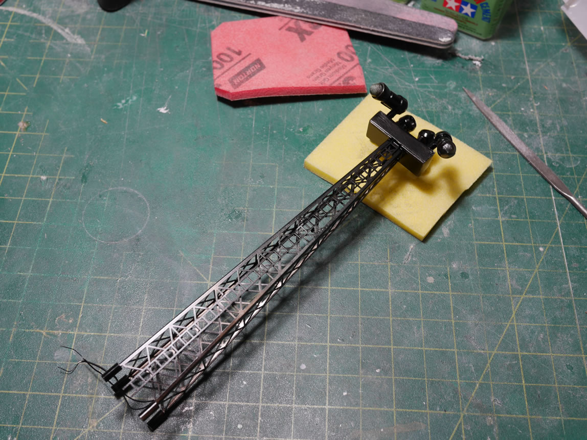
Speaking of lights, let’s visit the last progress for the light tower. I got the four spot lights wired together and glued the plastic bits together. A quick test makes sure I didn’t screw up anything in the wiring. The wires are twisted and run down one of the tower legs. They are glued into place and once painted, they should be fairly well hidden. The plastic box has now cured so some putty work is applied and sanded down. I used regular tamiya basic putty here because I wasn’t in a hurry to work on this piece. I had other parts to work on, so while the putty cured, I focused on other pieces of the project. Once sanded, the light bells were painted with a light grey, and the rest of the tower was base coated with finisher’s gloss black. I then finished the light tower with Alclad dark aluminum. Some holes in the base were drilled out and the plastic legs I created for the tower fit right perfectly; so I can eventually glue the assembly in place with the guide holes.
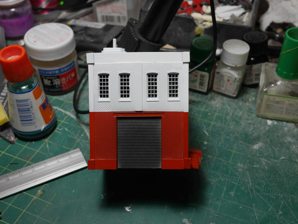
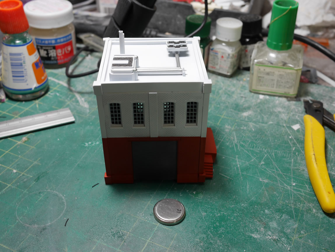
In the mean time, I masked off the painted windows for the building, then painted the top half in white. Once that cured, I masked off the top and painted the bottom half in brown with alclad steel for the garage door. The building is currently waiting it’s turn in the queue for some weathering and finishing touches.
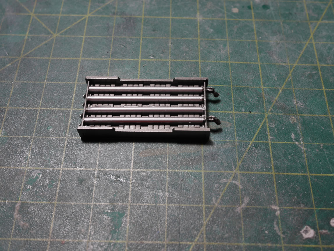
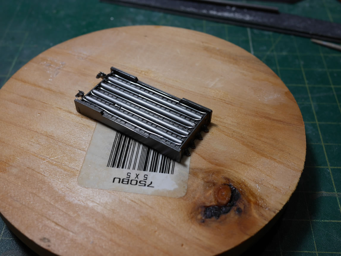
Next up is a little pipe tray that I threw together. I mixed some clear resin and poured it into the tray as kind of a cooling pool type thing. That’s once piece of the pipe structure that’s complete; now I gotta worry about the rest of it.
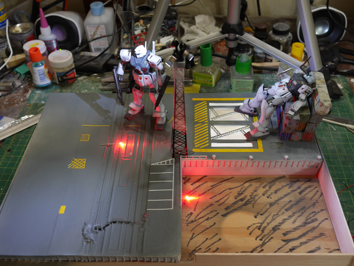
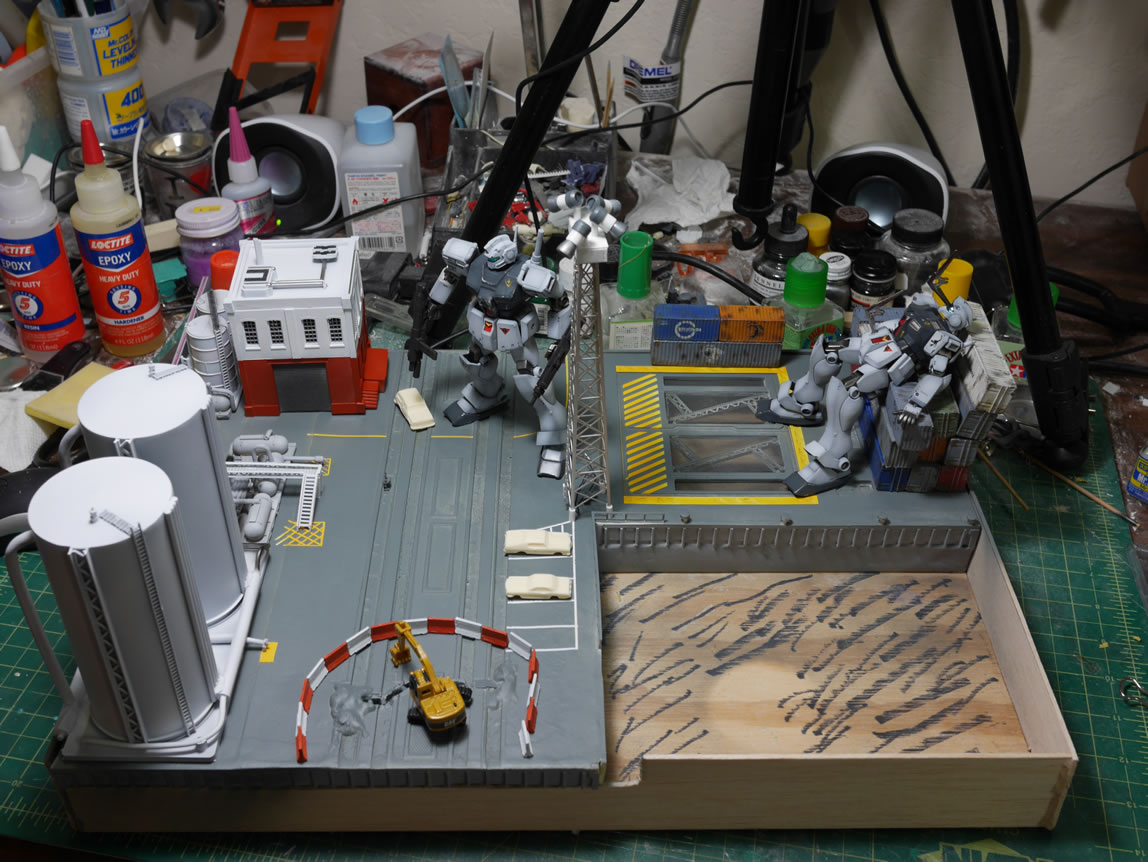
With the building painted and parts of the silos and pipe structure painted; I threw completed parts of the base together for a quick progress picture. These are the pictures that really show the project’s progression. I have the little barriers 3D printed and painted. And we see the results of the masking job from earlier in the post.
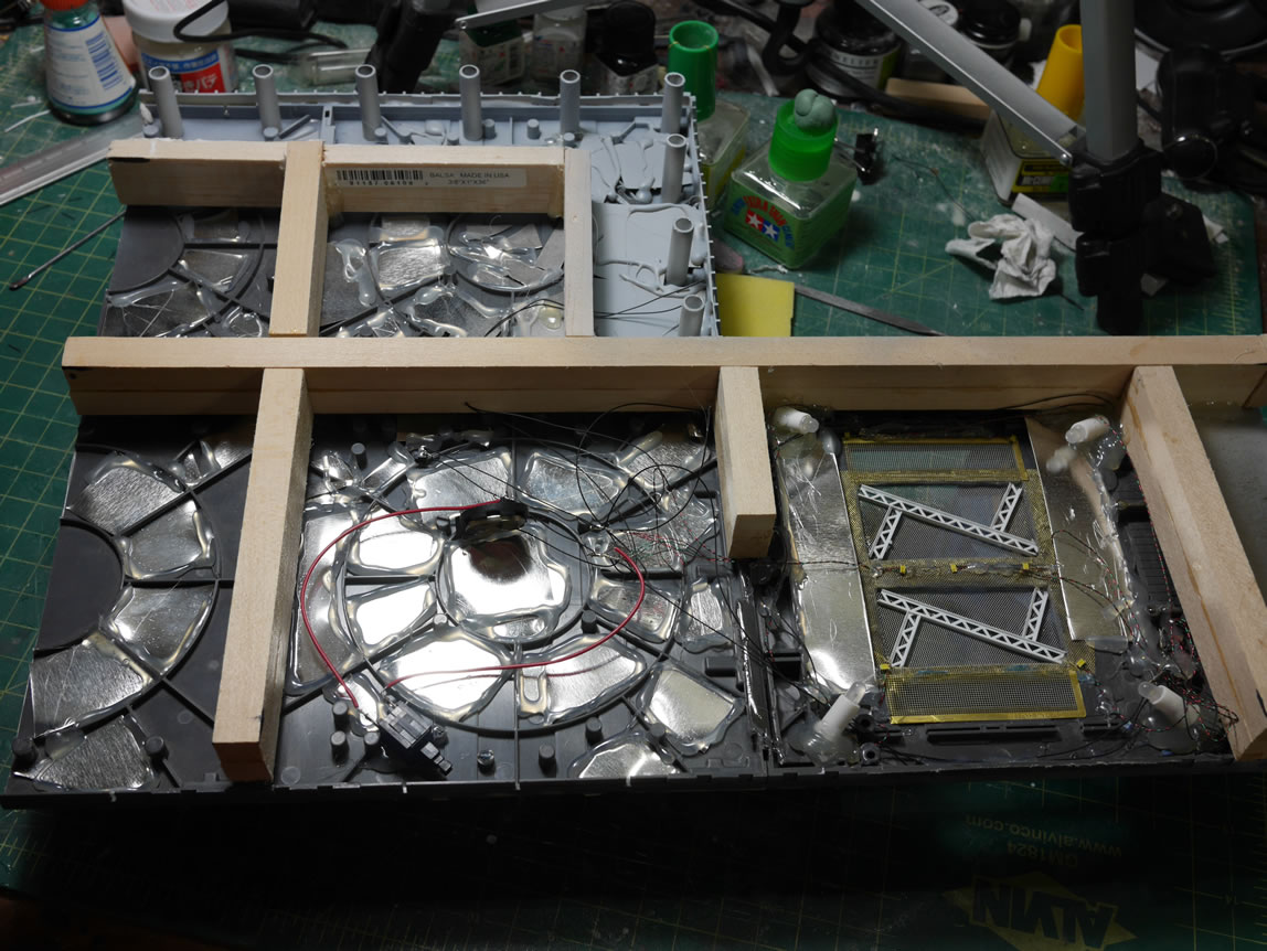
Having focused quite a bit on the top side of the base, it was time to give some attention to the ugly bottom side. The wiring is a mess. Prior to this update, the wiring was all done in parallel. Meaning, all the negative ends for every LED is tied together and all the positive ends for every LED is tied together, then with a push button switch and a 3 volt button battery source completing the system. This won’t work. I have a mix of LEDs, different sizes, different colors, different types. The size and types don’t really matter too much. It’s the color difference. Different colored LEDs require a different amount of power to light it. Since I’m using two red LEDs, a set of 4 white LEDs in the tower, and a whole set of white LEDs for the underbase lighting; having these run parallel won’t work.
Since it has been a while since I posted a new video; I made a video of this whole process; condensed into a 20 minute long video. The video explains the difference between parallel and serial wiring schemes. And for this project, I’m actually using both schemes; just in a different hierarchy.
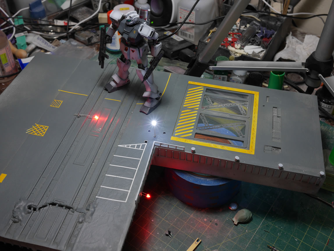
The following pictures were taken while I made the video. The wiring scheme was clipped apart and re-arranged. The push button switch was swapped out for a reed switch; and the power source was swapped to a bigger 9 volt source. I have two sets of white LEDs that are wired in parallel with one another. The two red LEDs are wired in parallel. So effectively, I have 3 sets of lights: the under base white LED set, the tower light set, and the red light set. For these three, I wired them in series, so that I can successfully power all three light systems off one battery and switch assembly.
Putting the reed switch strategically under one of the GMs that just so happens to have some magnets in its feet; I can power on the whole system by just placing the GM on the base.