July 29, 2019: The old adage that if you don’t use it, you’ll lose it; is very true. I did some 3D designs for the Dom Barrage project but once those pieces were designed and printed and I spent more time with the hands-on side of things to finish the build; the 3D design skills flew out the door. Since the Dom project was fairly intense, I wanted to relax a bit and work on something simple like the Zaku Exceed head. I finished the Gundam Exceed head while in the middle of working on the Dom project as a quick break. But as I started looking at the Zaku heads and thinking more, I realized that I should keep practice on the 3D design. I needed to relearn a few things but it is kind alike riding a bike, once you get used to the balance and everything, it just becomes muscle memory. So my quick and simple project kinda blew up into a full blown custom project….converting the Zaku Exceed head into a Gouf Custom head with a full bust.
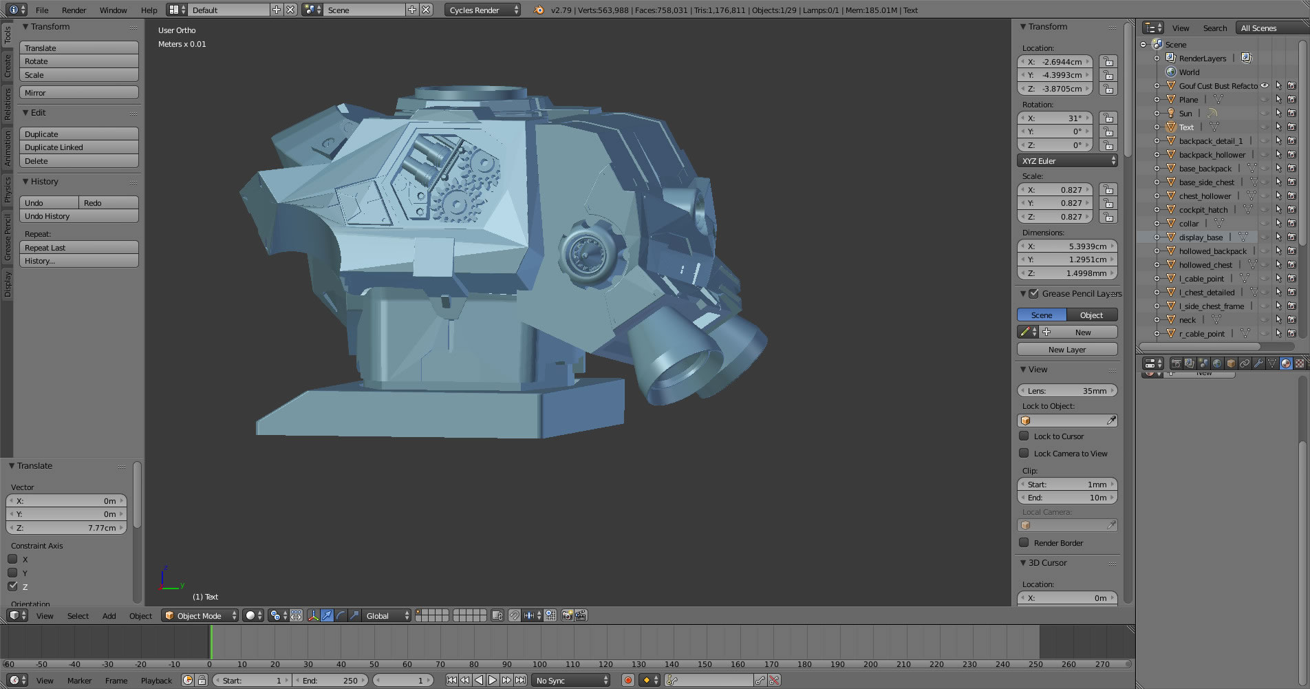
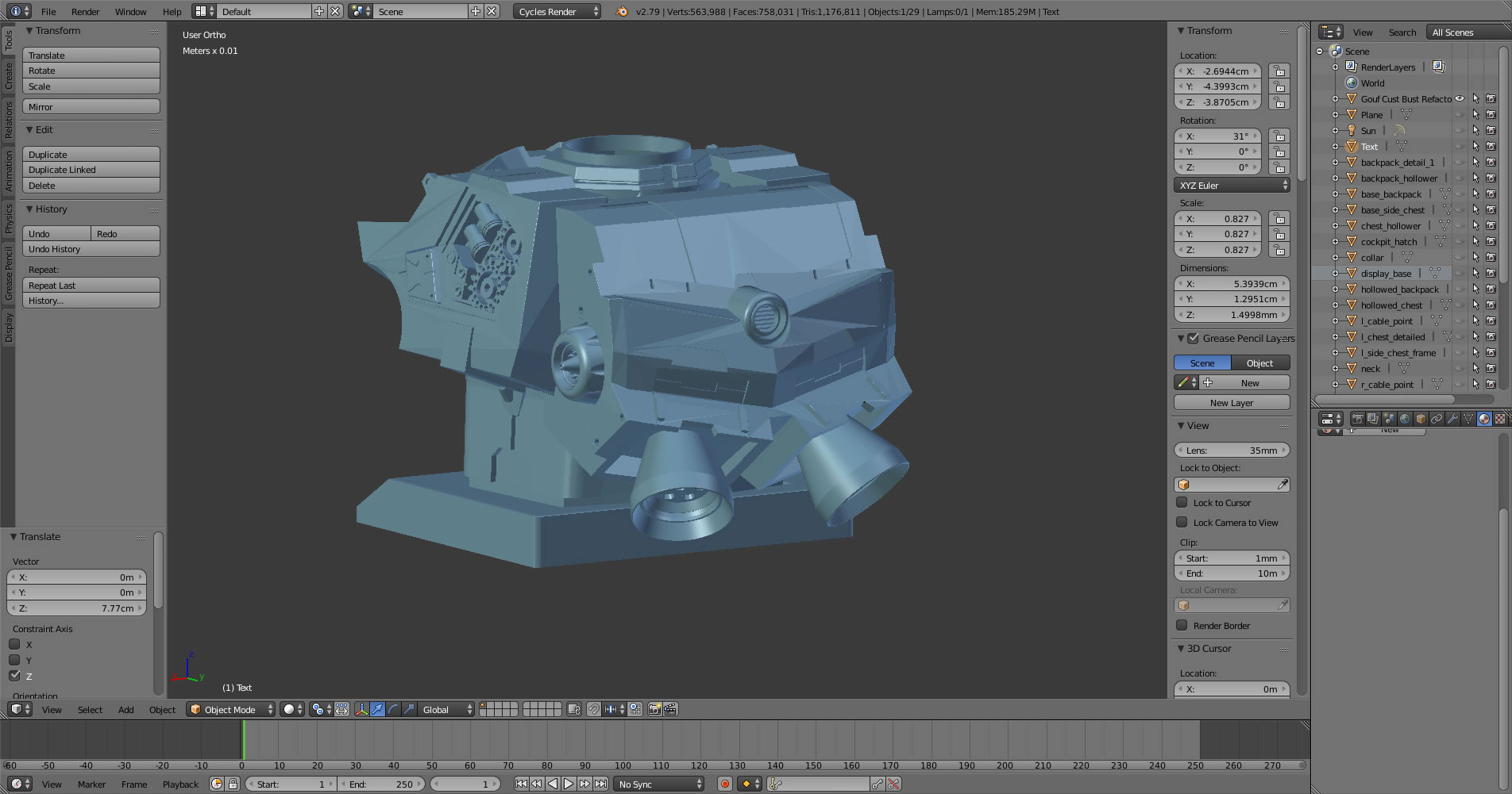
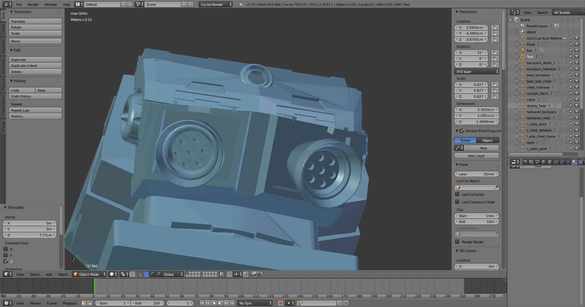
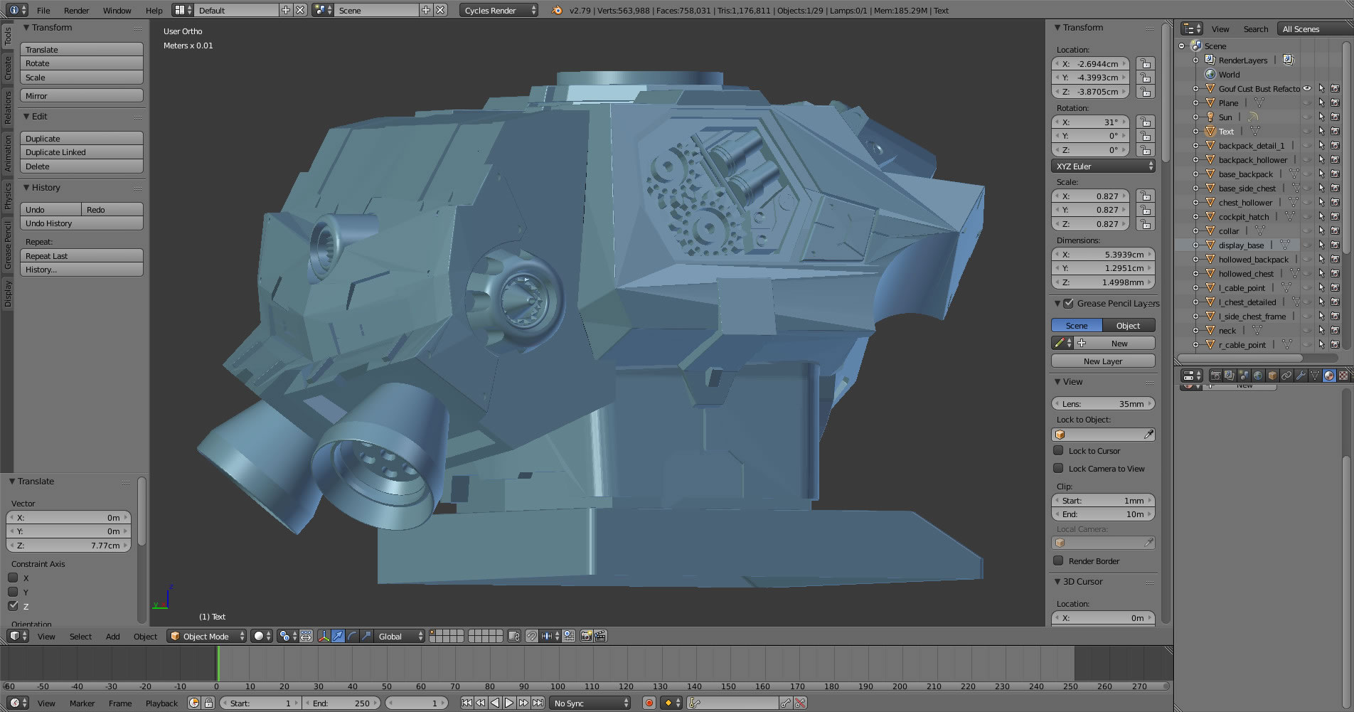
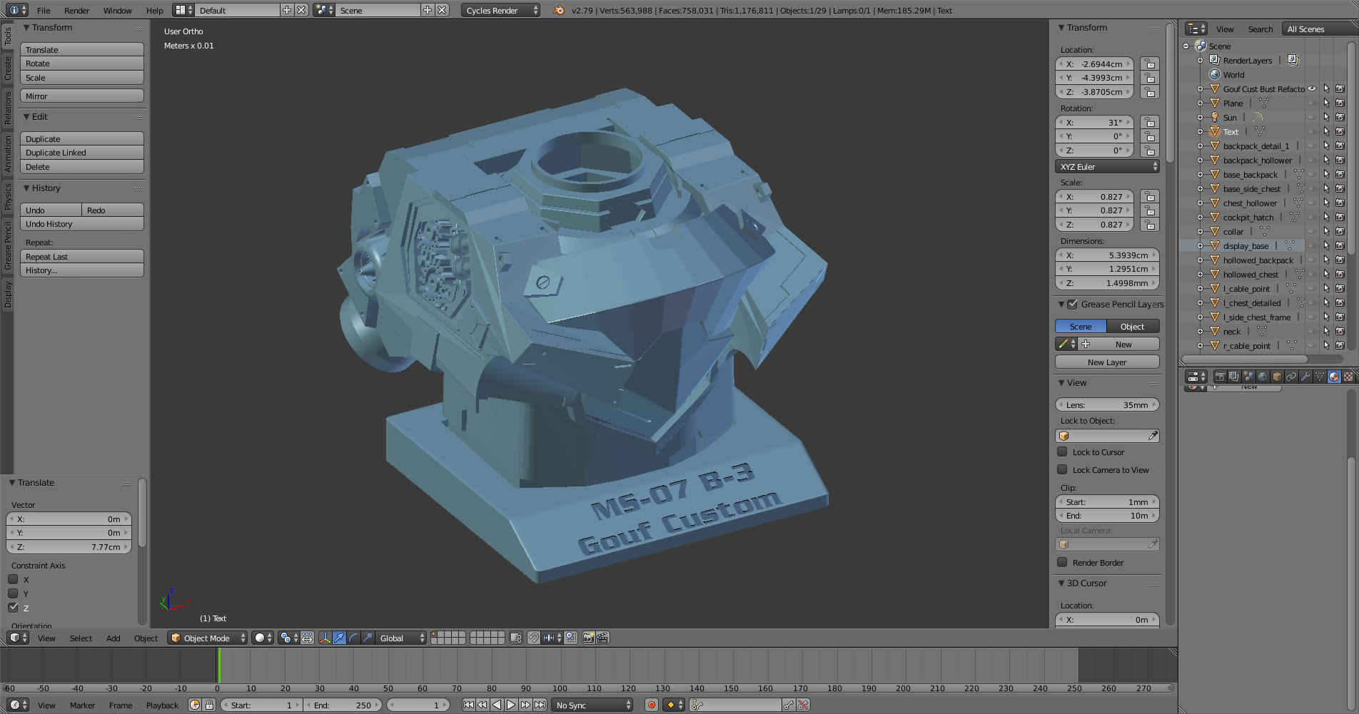
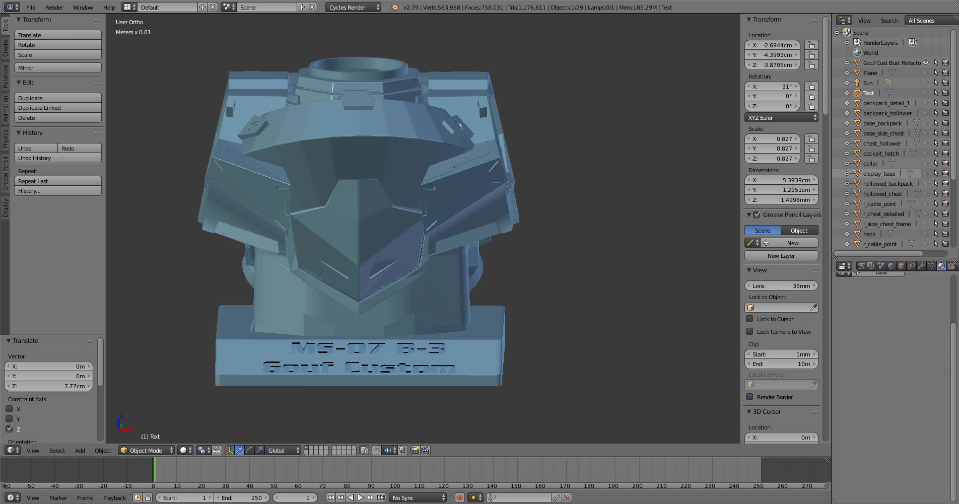
I’m getting much more comfortable with the design, but I’m still VERY novice at it so the end result isn’t the greatest in terms of properly designed 3D files. This first set of pictures are the initial build progression via Blender. The basic idea is to block out the design using reference pictures I took from the NeoGrade Gouf Custom Conversion kit I built years ago. Once the blocks are laid out, details and shaping can be done.
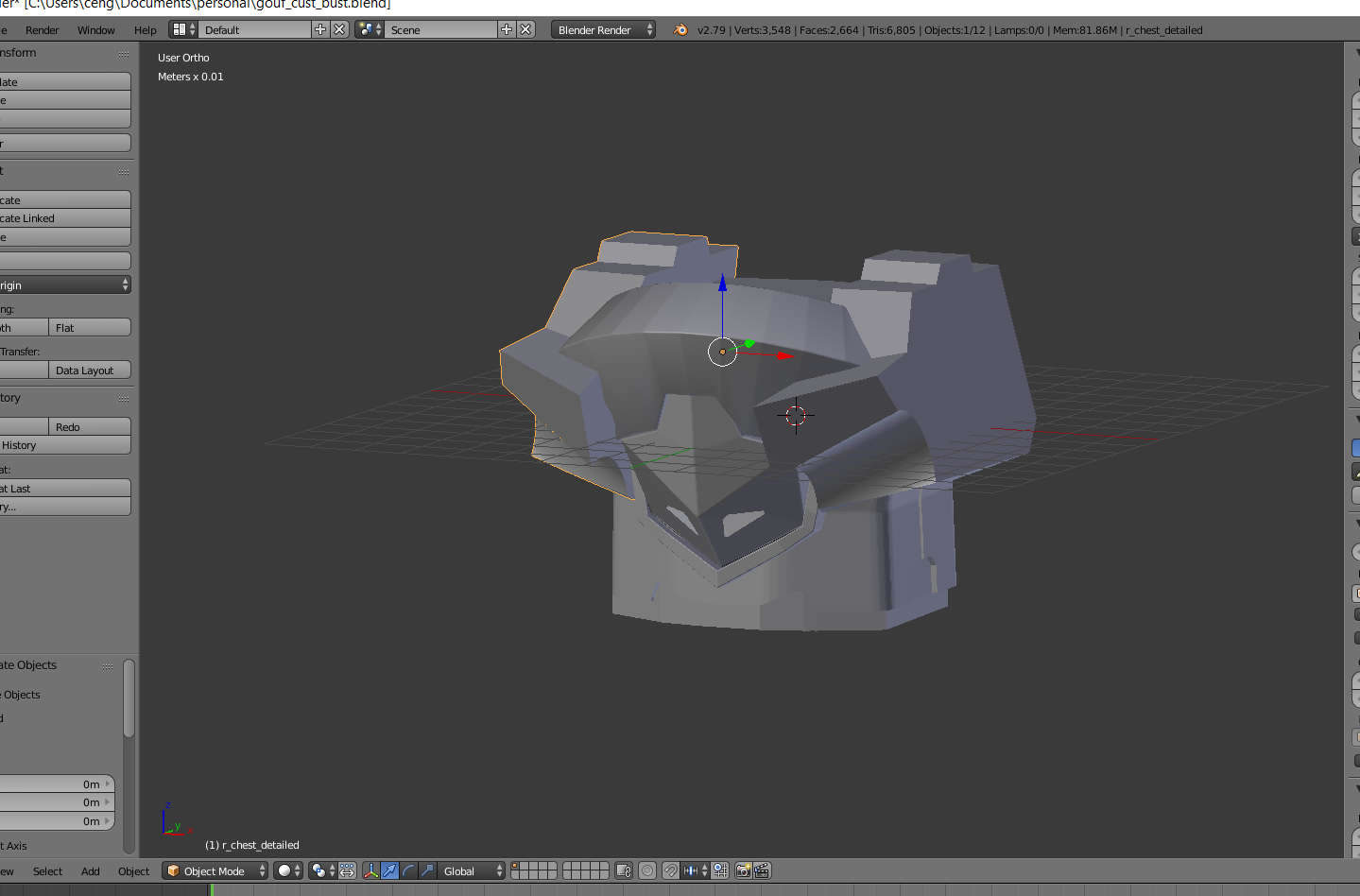
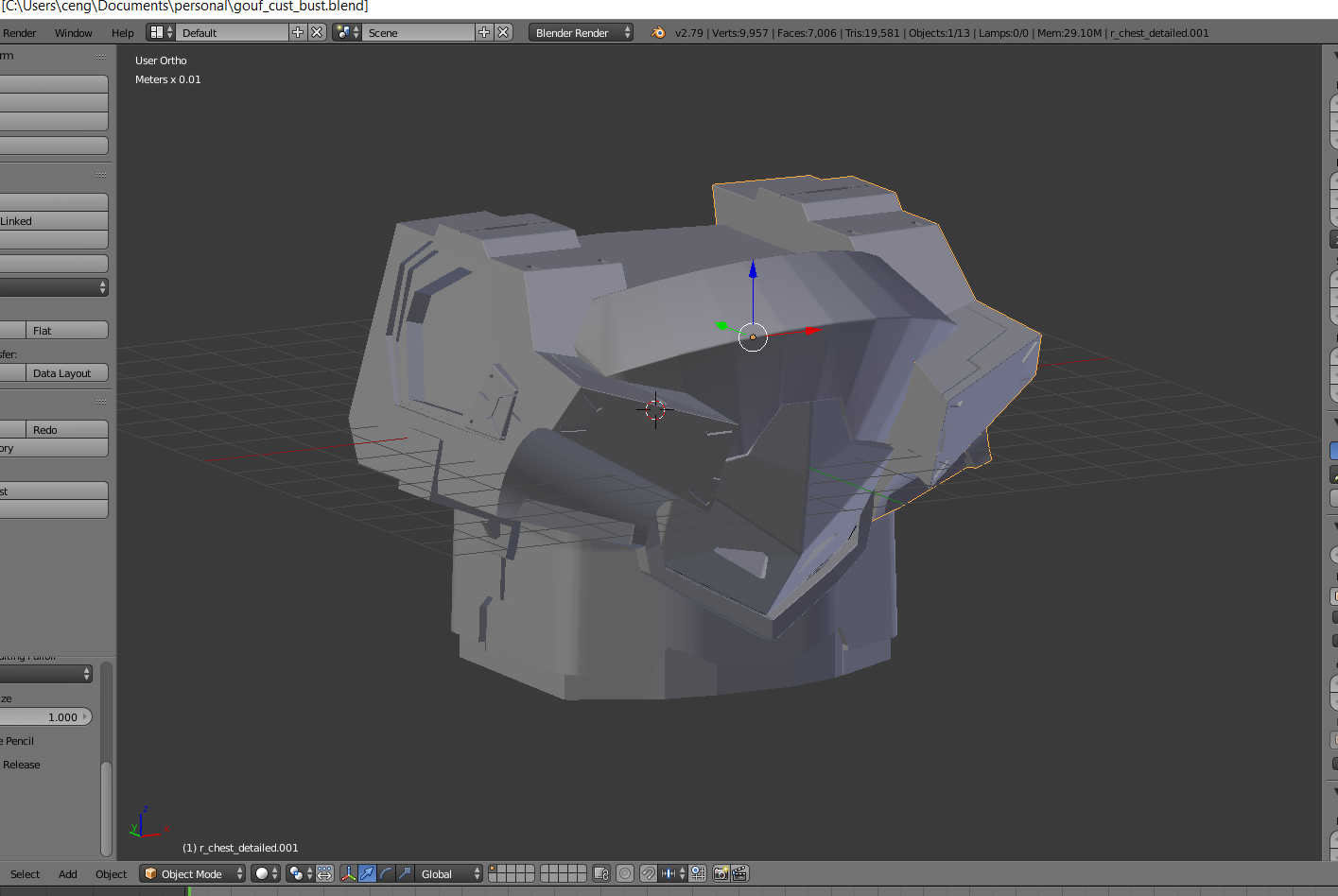
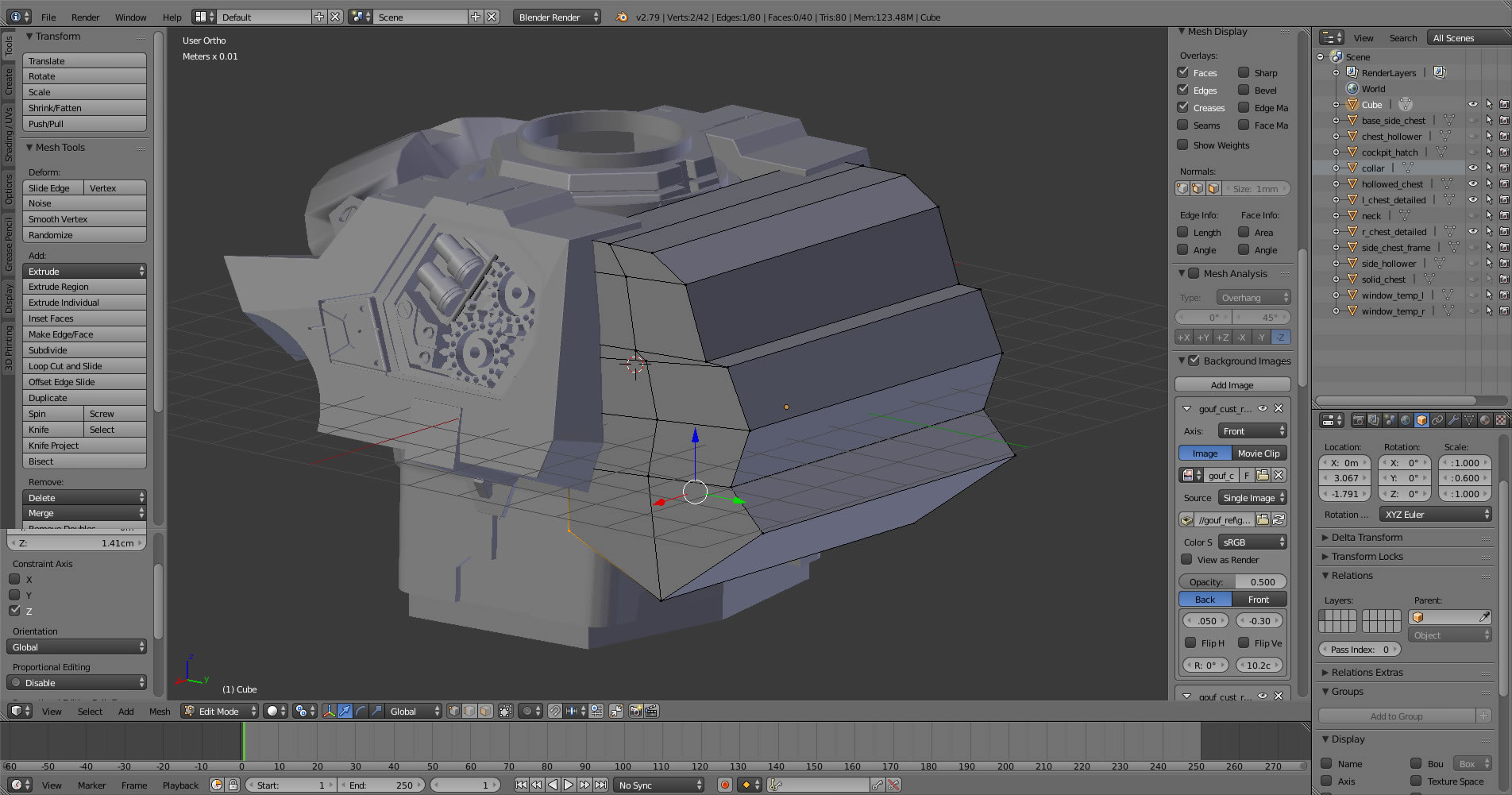

The design process didn’t take too long this time around since I learned so much from the Dom project. I just needed to relearn a few of the shortcuts and techniques are easily forgotten with disuse. I learned a bunch more while working on the design this time around too. The whole design process took about 4 or 5 days. Not too shabby. Since there is nothing physical, it is difficult to stop and take progress pictures but I did take a few in progress screenshots via Blender.
I was originally going to just do the chest piece; but sometime last week, I started working on the backpack and I think this helps balance things out. I also designed this in pieces for easier print and to leave the project open for making an exceed model conversion kit. Folks have been asking for the STL files, but honestly, the design isn’t solid enough. There are TONS of issues because I’m still learning correct order of operation and good 3D design methodology. I want to take another couple of classes on 3D design so that I get faster and better at the process. The Form 2’s slicer is VERY forgiving and my poor designs are actually printable because the slicer does a pretty good job at guessing the mess that I was trying to build and then print it.
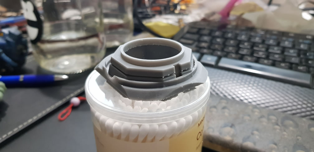
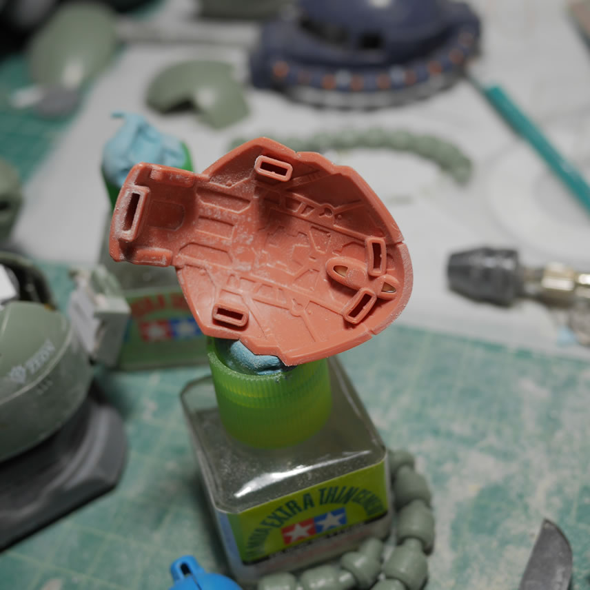
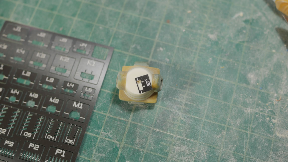
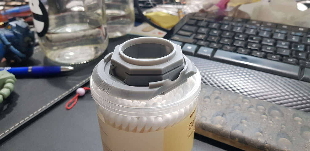
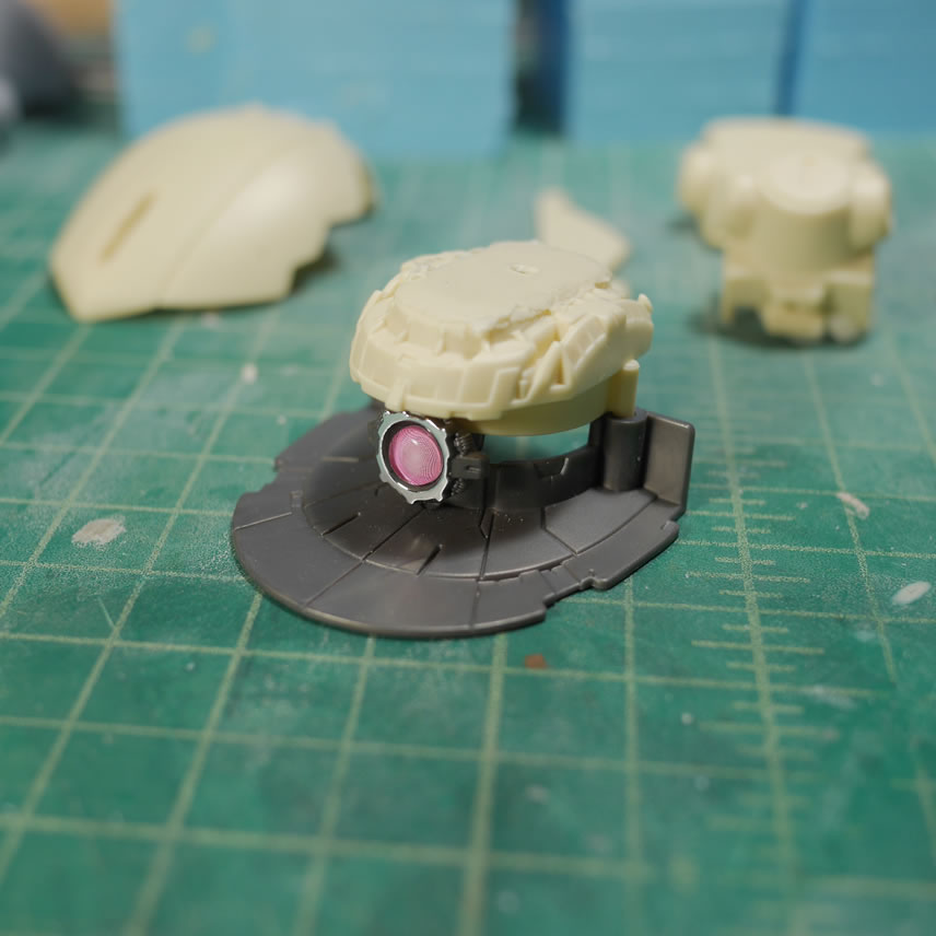
Once I started getting close to finishing the design, I printed out a quick test piece. This piece will determine the actual scaling for the rest of the bust design. The collar piece will connect the rest of the bust to the Zaku Exceed Head model. I measured the diameter for the bottom of the head and did the math to figure out the correct scaling from the Blender files to the Form 2. From my design, I need to scale this at 14.14 times. And the collar is a small enough piece that if I printed it at 100 microns (.1mm resolution) it shouldn’t take too long to print.
The collar printed in a few hours and after clean up and some extra UV curing, the test fit is perfect. I now know the scale factor for the rest of the design and kick off the main chest piece design in the printer. The chest piece is separated into 5 pieces, the two cockpit window inserts, the side chest details and the center chest block. I printed the center chest piece at 50 microns (.05 mm). The print time estimation was 25 hours.
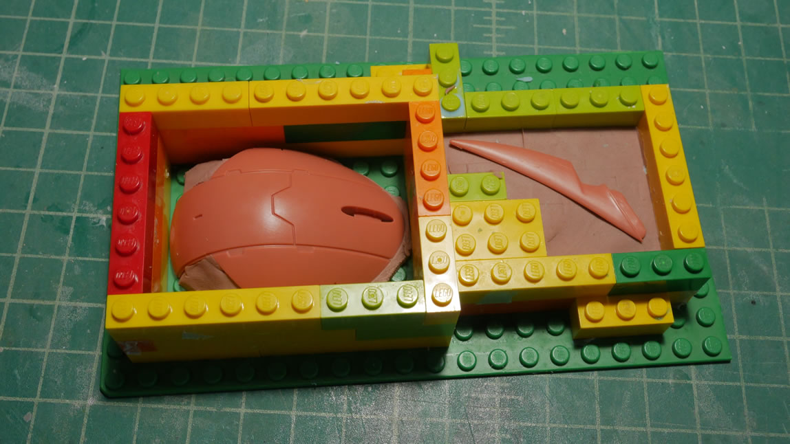
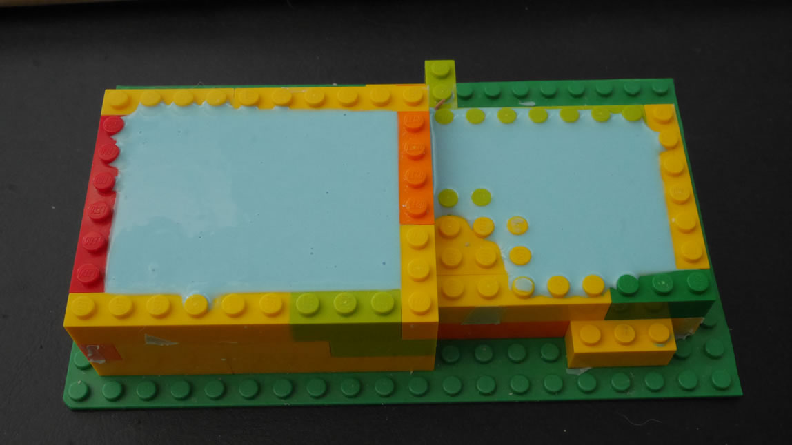
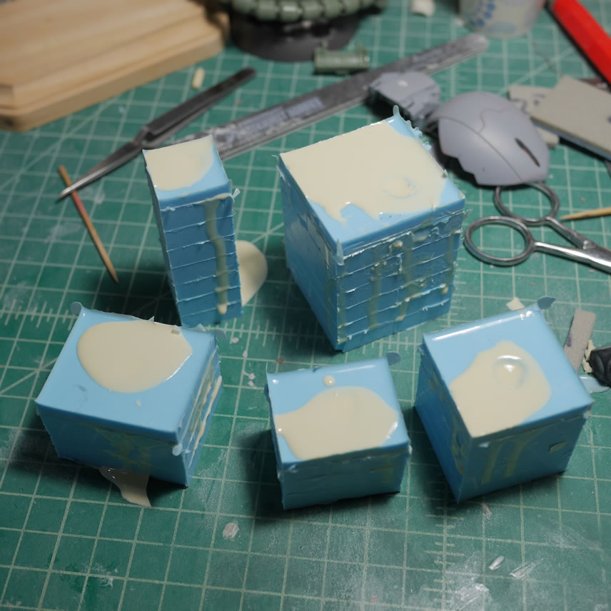
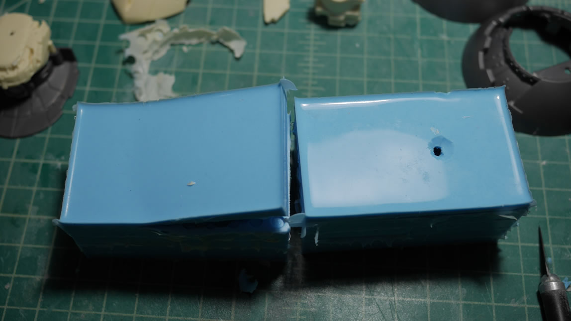
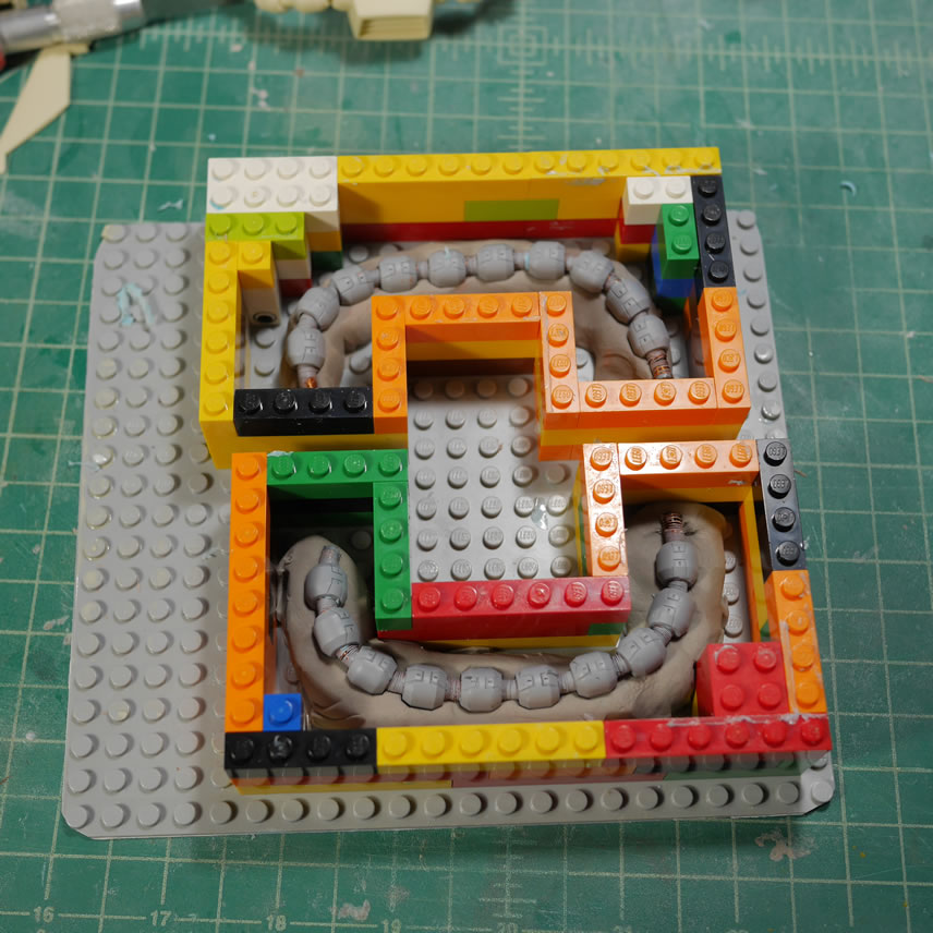
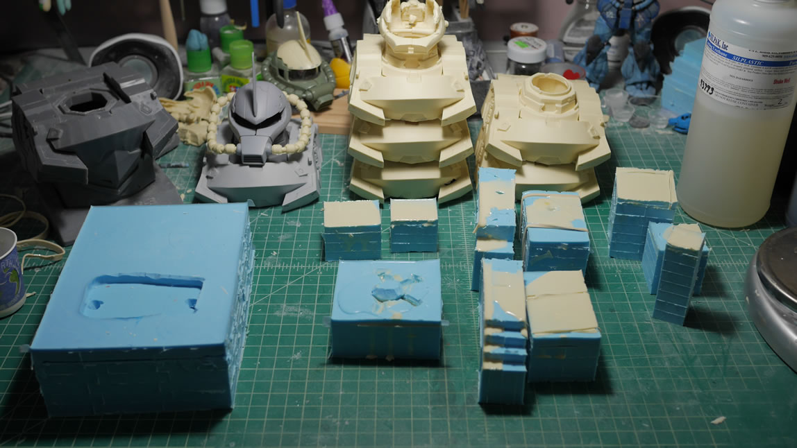
I picked up the red Zaku head on my trip to Japan several years ago and picked up several green Zaku heads recently at AX. Since I only had the 1 red with the commander fin; the first step is to make a copy; so a lego box was made with playdough lining the bottom and the part is covered with liquid silicone to make some molds. The same is done with the commander fin.
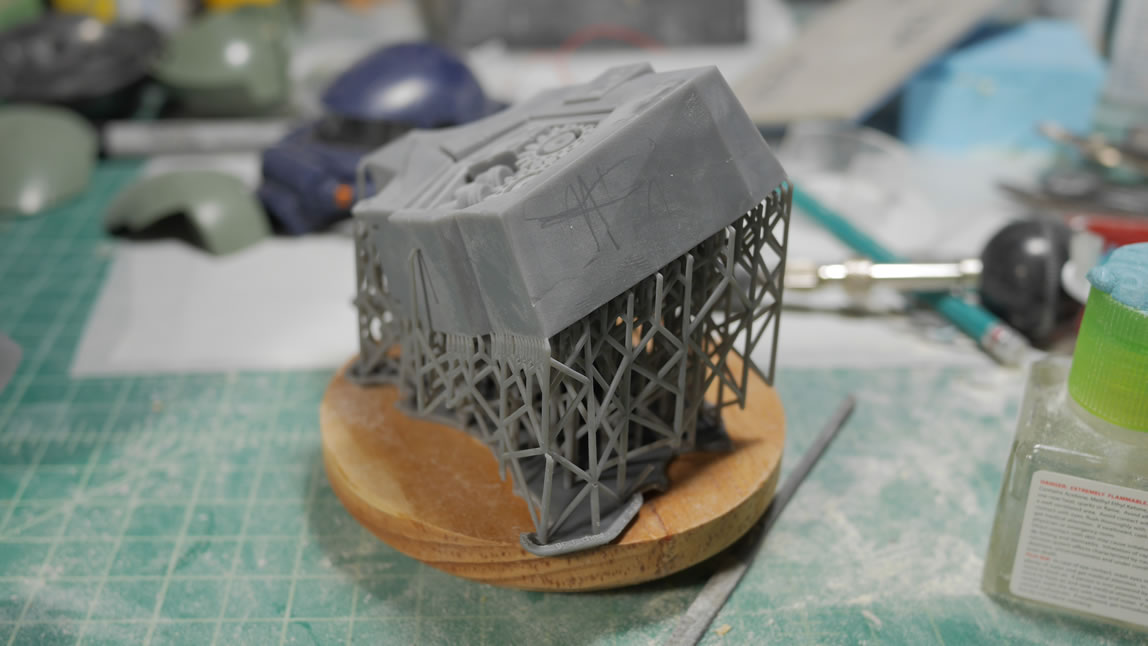
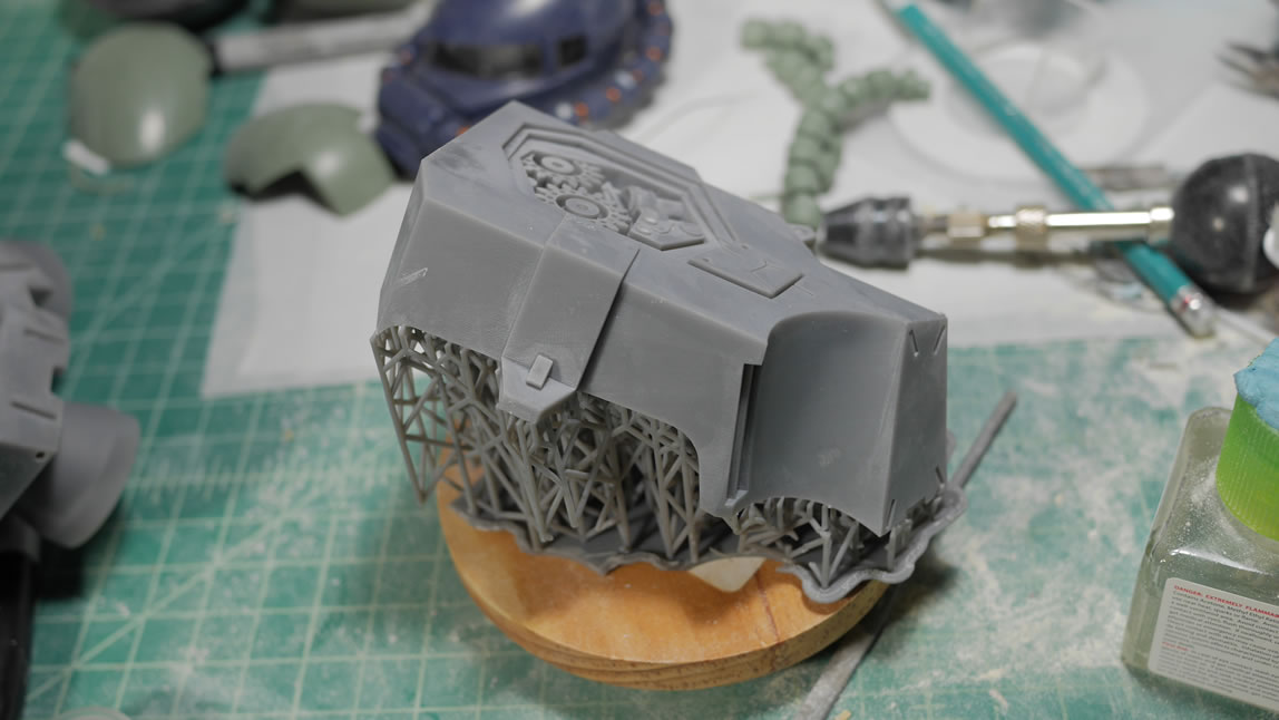
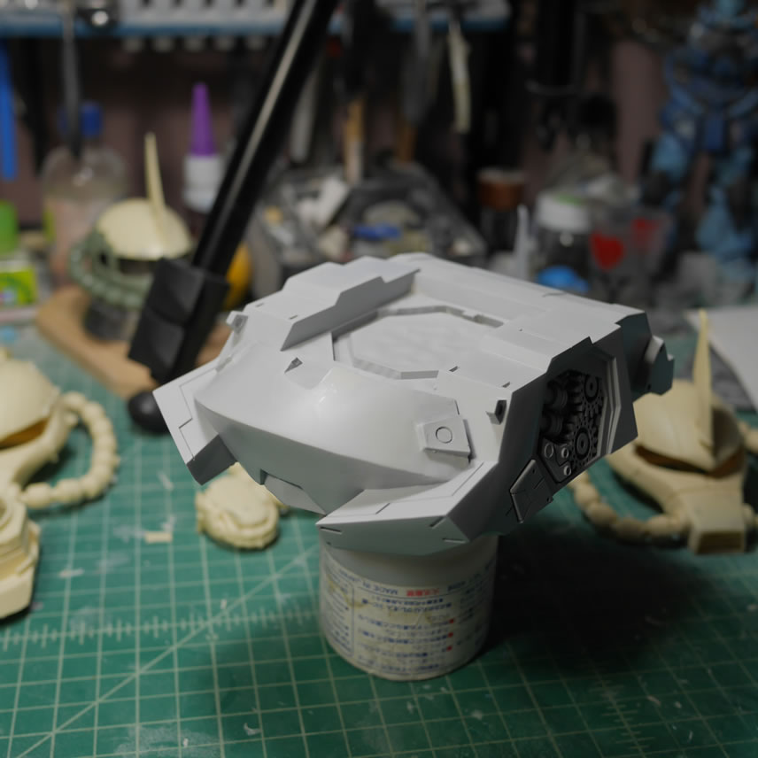
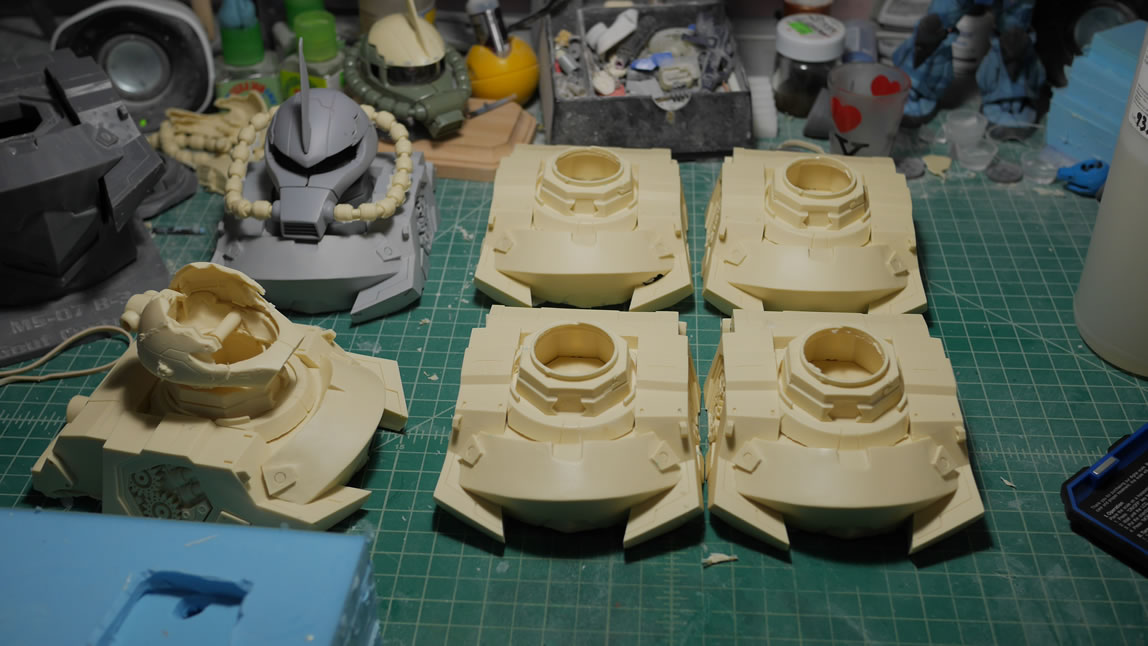
The chest block actually took 27 hours to print. The block of resin was transferred to a isopropanol alcohol bath and left to soak for about 15-20 minutes. Once done soaking, it was rinsed off and dried and UV cured in some sunlight. The supports are clipped and pulled away leaving a giant block of 3D printed resin.
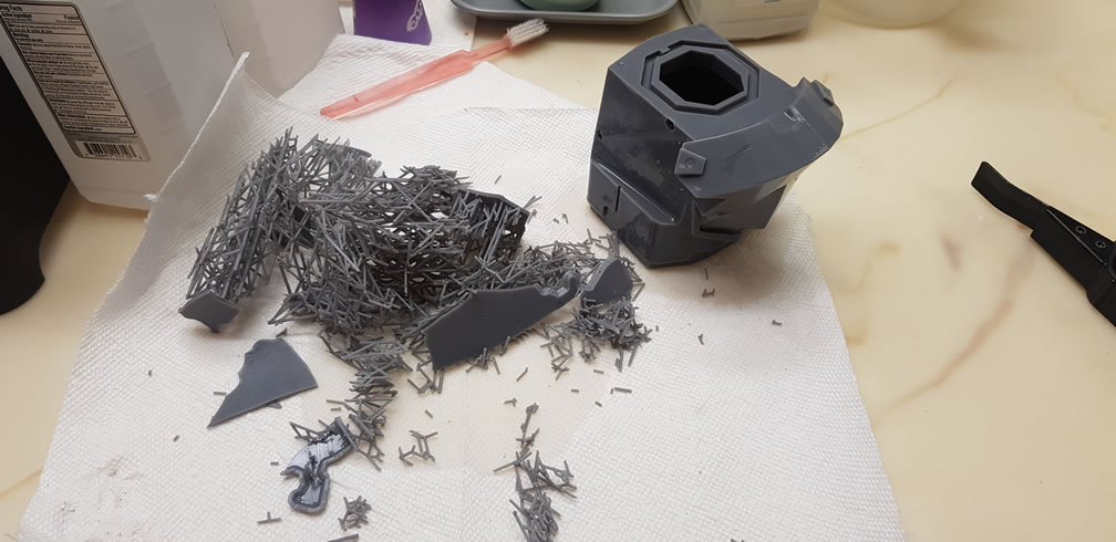
This block of resin needs some clean up, and again, since my skills with 3D design isn’t quite there yet, there is A LOT of post processing that needs to happen to get this to the priming phase. But in just 27 hours, the chest block is printed and looks pretty good IMO.
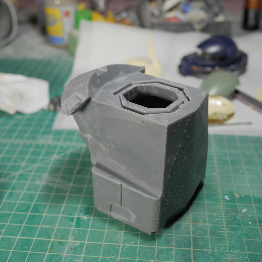
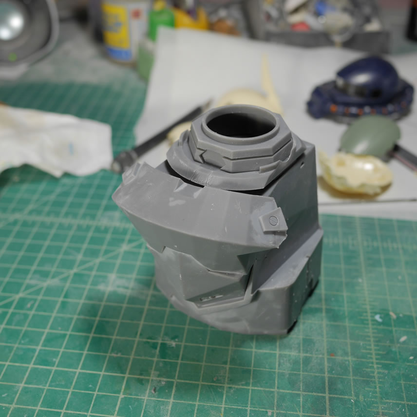
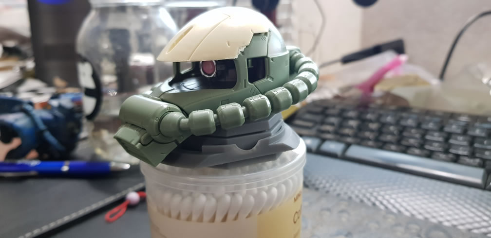
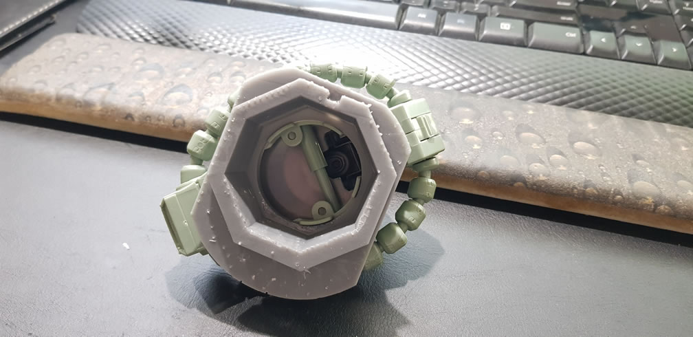
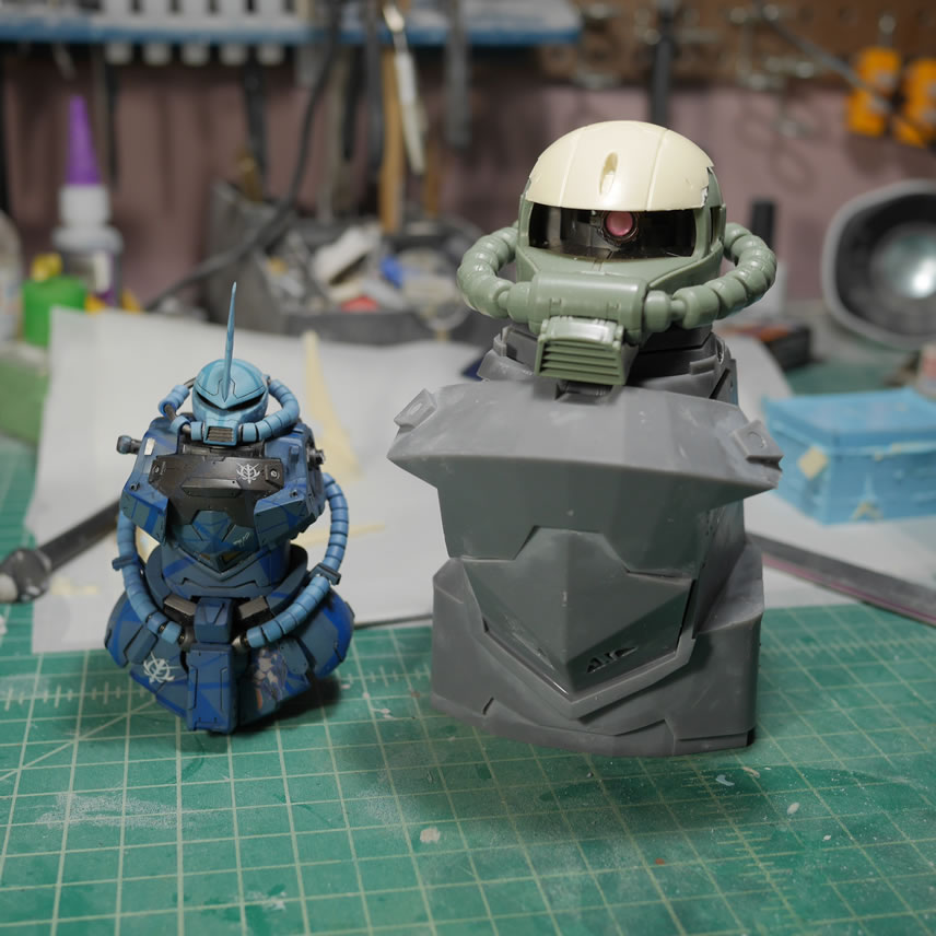
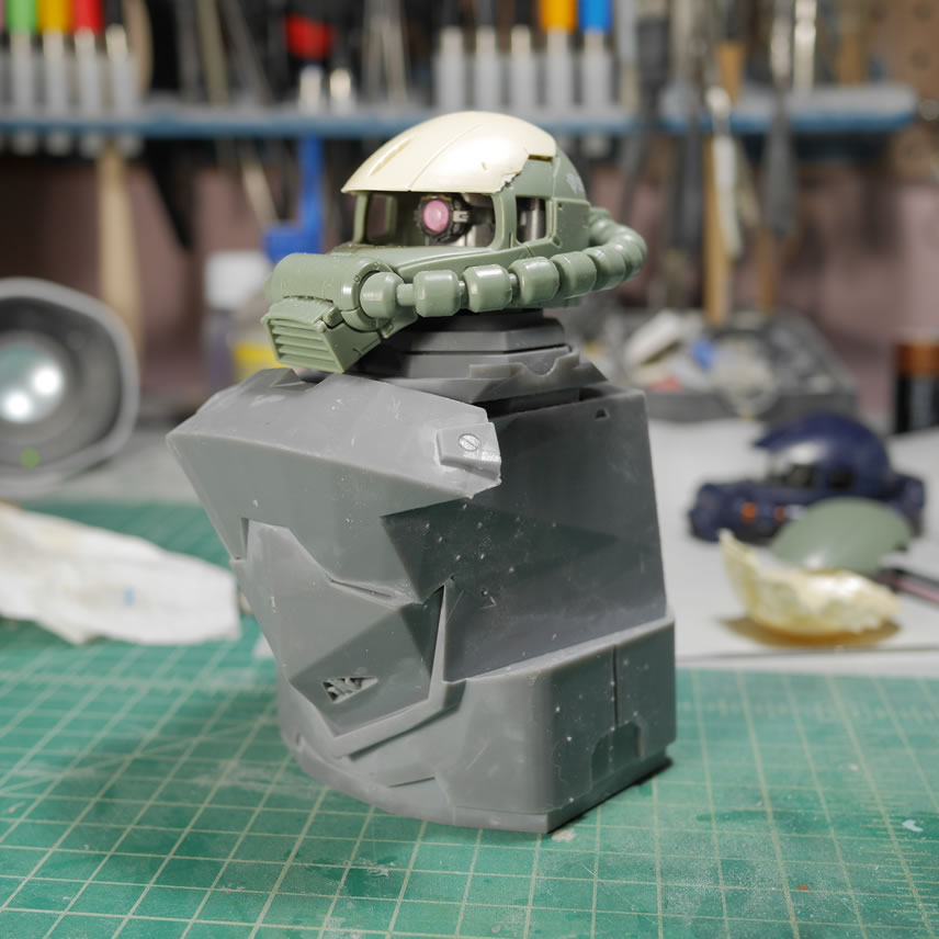
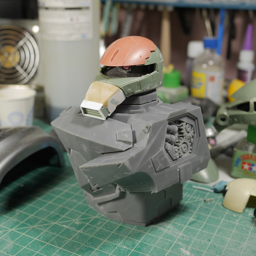
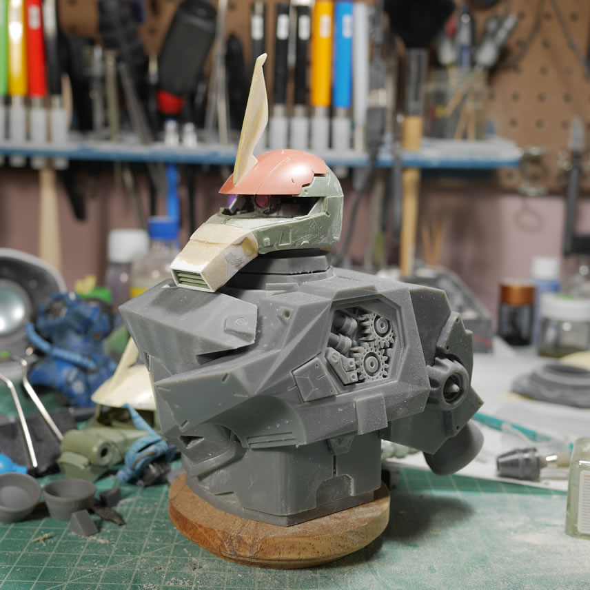
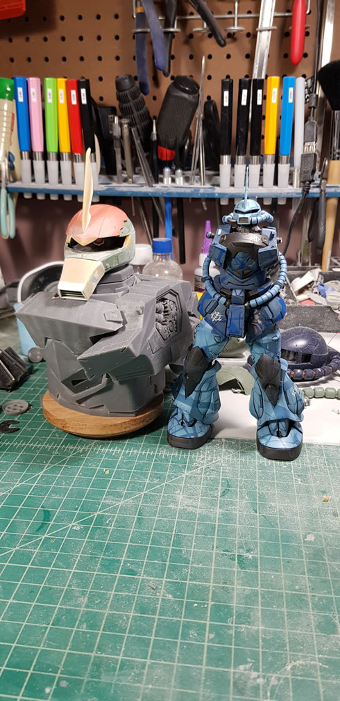
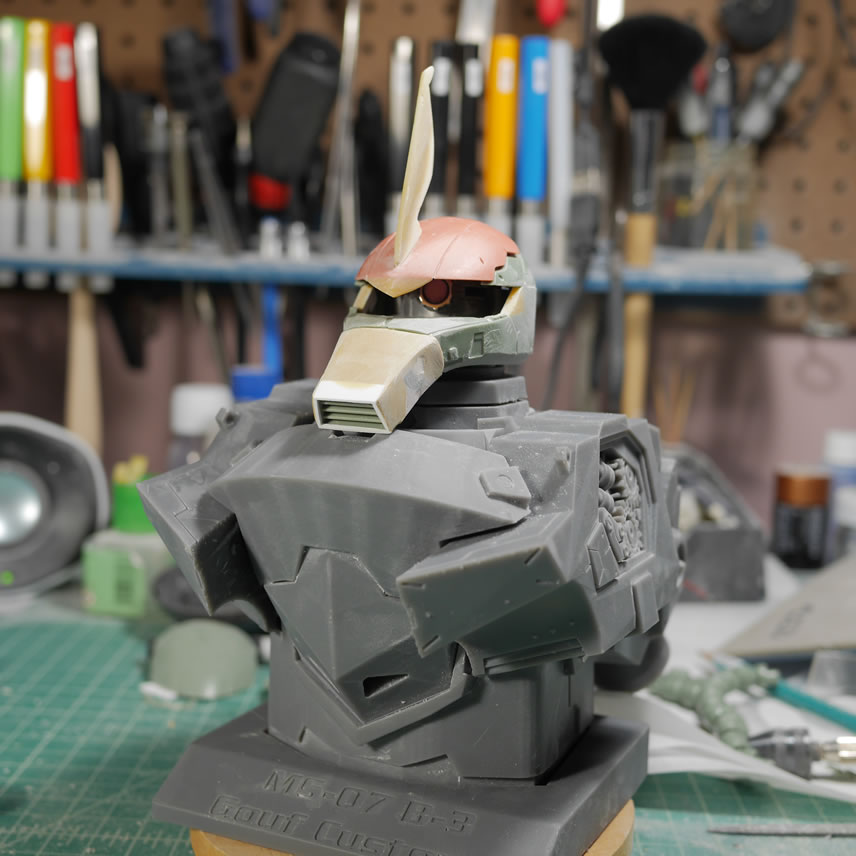
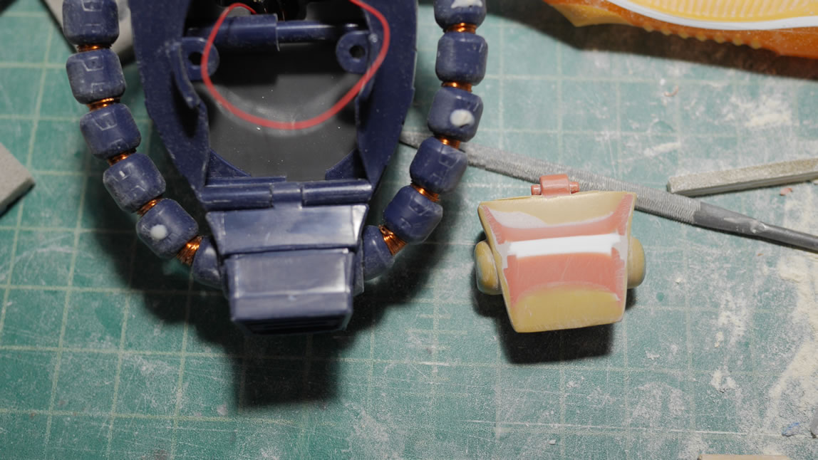
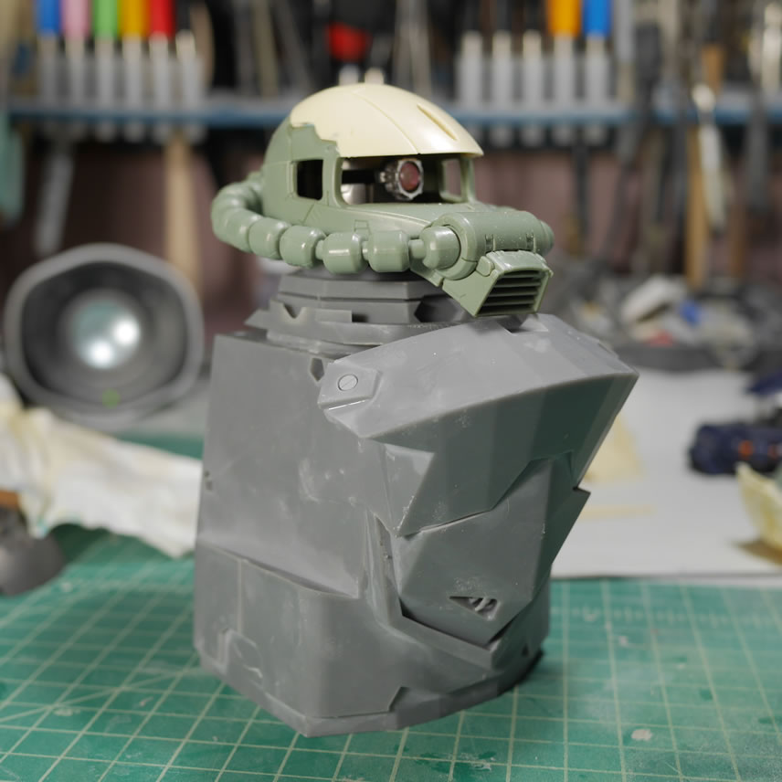
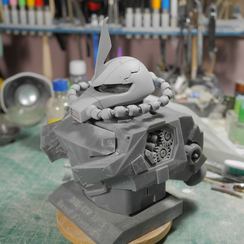
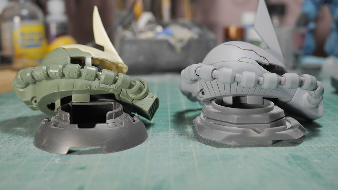
Now some test fitting with the collar and Zaku head. There are a few problems discovered here. 1. the collar doesn’t sit into the chest block. Poor design and lack of forethought. The bottom of the collar piece is angled incorrectly and too large to fit the angled slot of the chest contact area. This is purely a mistake in design. Having the collar as a test piece was perfect to catch any gotchas that I can then translate to the rest of the kit that hasn’t been printed. I just went back into blender and modified the collar to correct the fit issue. 2. The collar was too short, the Zaku’s nose doesn’t clear the front of the chest. So regardless, the collar piece needs to be adjusted and reprinted. This bust piece is going to be large. The comparison to the MG sized torso piece should be a pretty good indicator.
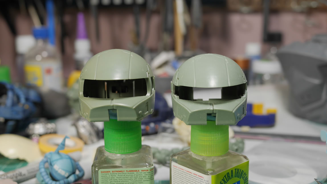
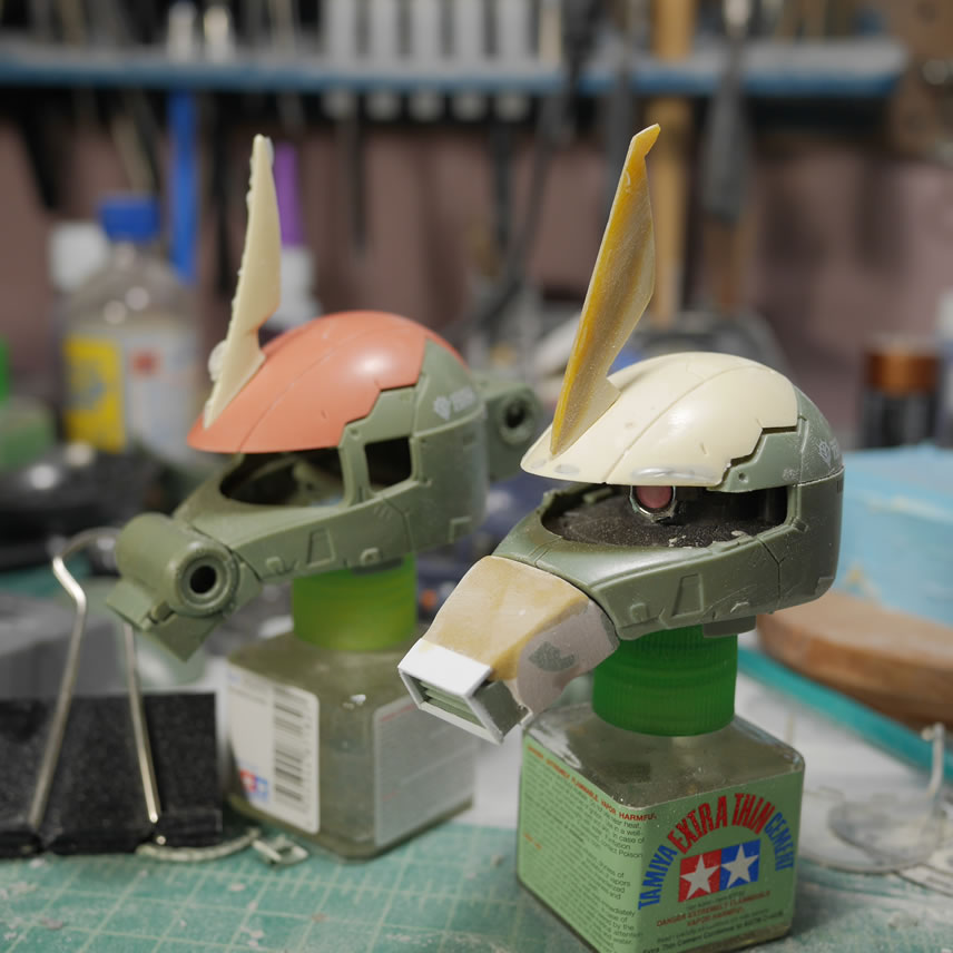
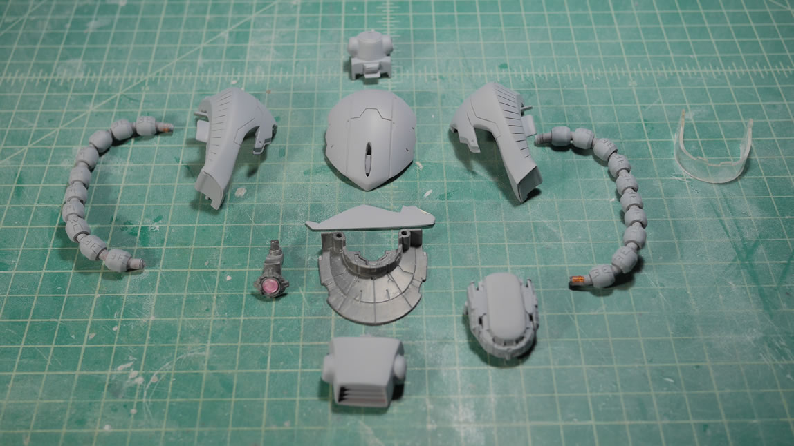
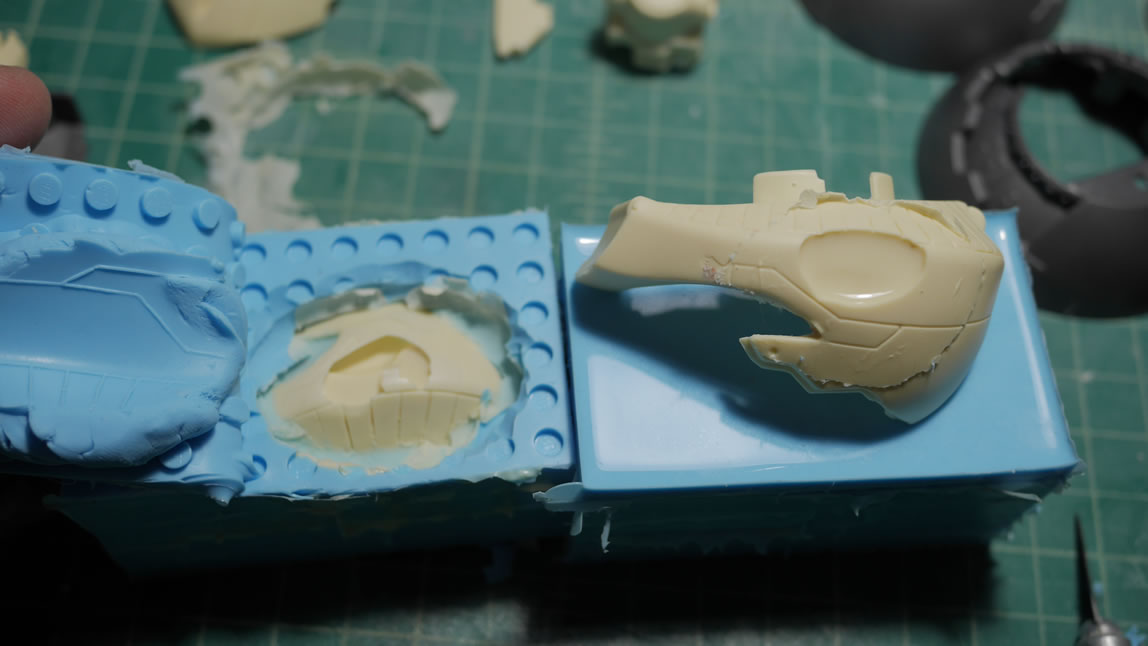
The molds for the commander Zaku are done so a few casts are made. Time to get to more cosmetic mods to the Zaku. It is NOT a Zaku boy; so we need to bring out the cutting tools. Hobby saws are brought out and just like dropping the top like one would do a top chop for a hotrod. I just ran carefully along the top indented edge of the head and cut the head side pieces in halves.
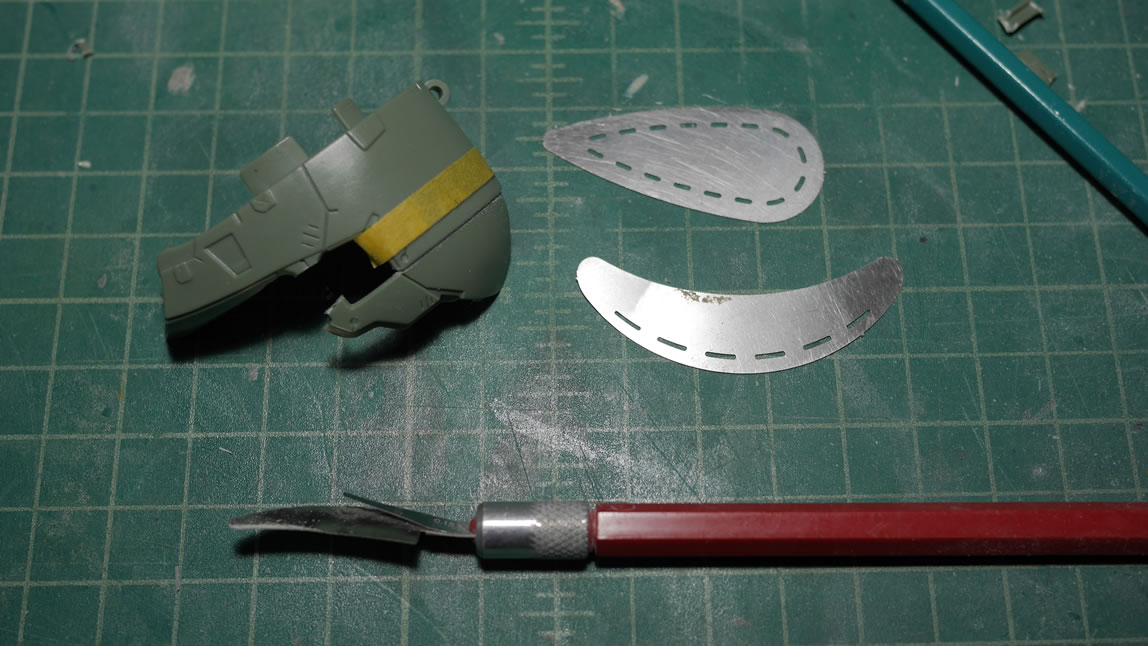
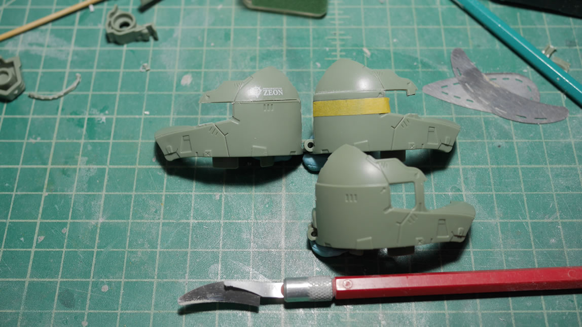
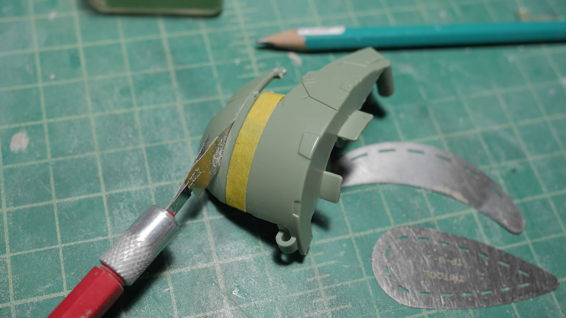
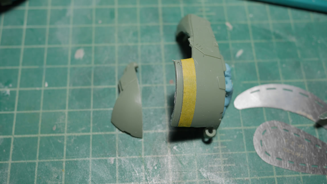
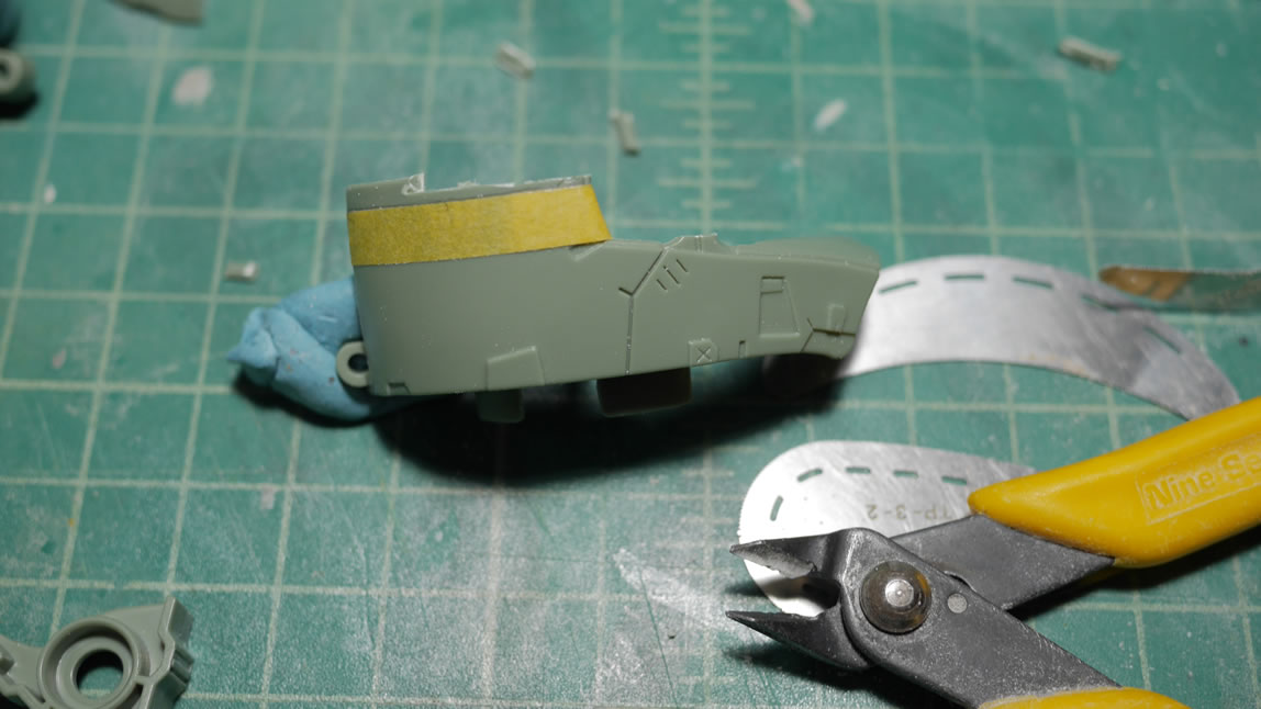
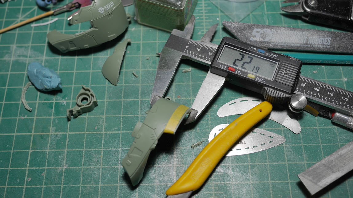
Tamiya tape is used to draw in the amount of plastic to remove and the lower halves of the head are sanded down to remove plastic material. Measuring is important since the two halves are being sanded down independently. I don’t want to over sand. Once the two sides are measured and sanded down correctly, the tops are glued back into place. And a quick comparison with the original Zaku look should be fairly visible. The window pillar was also removed.
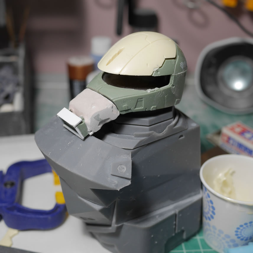
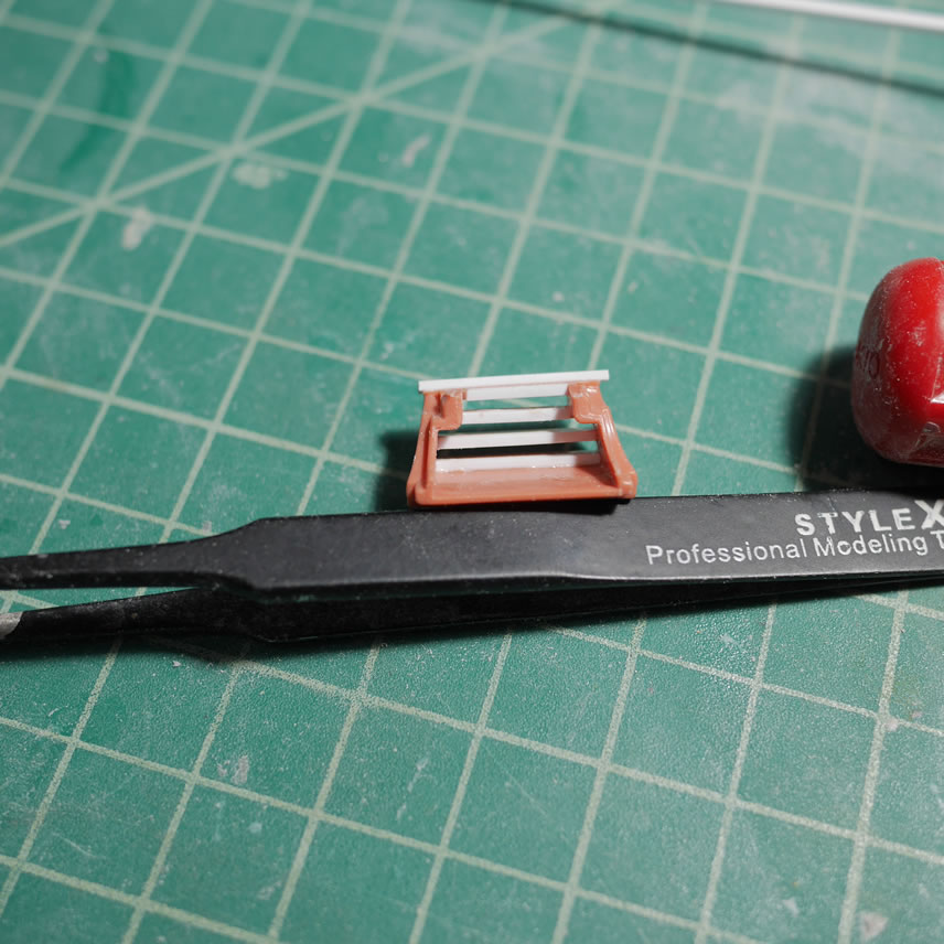
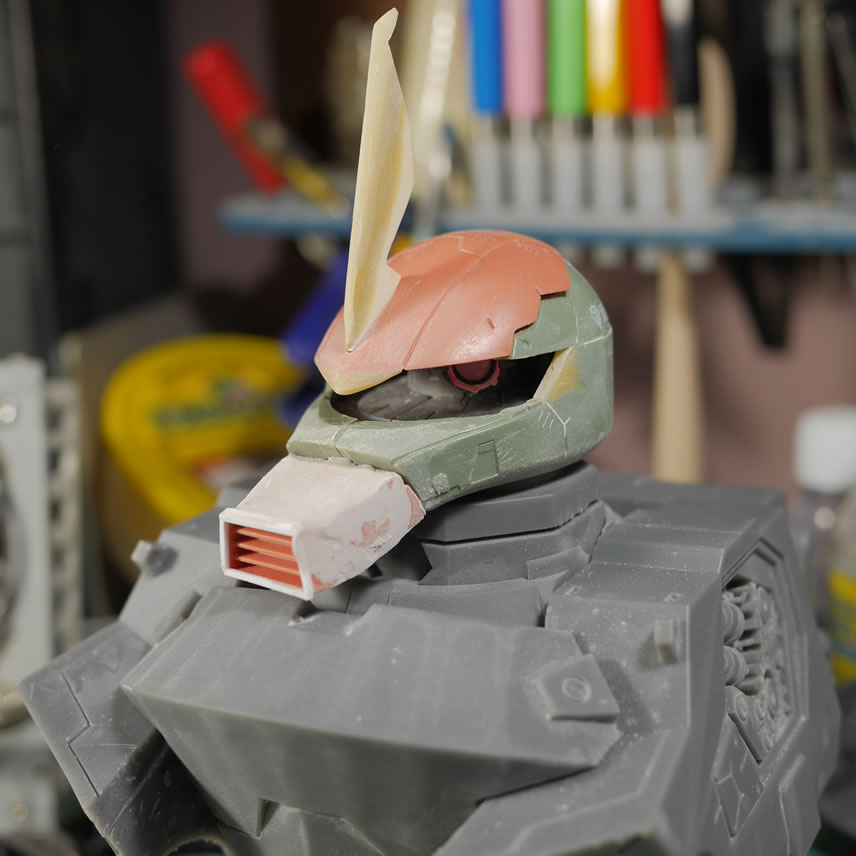
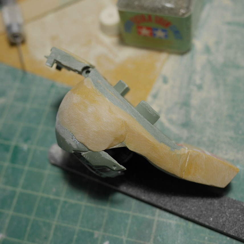
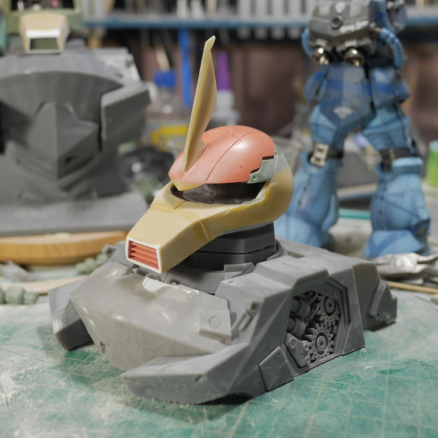
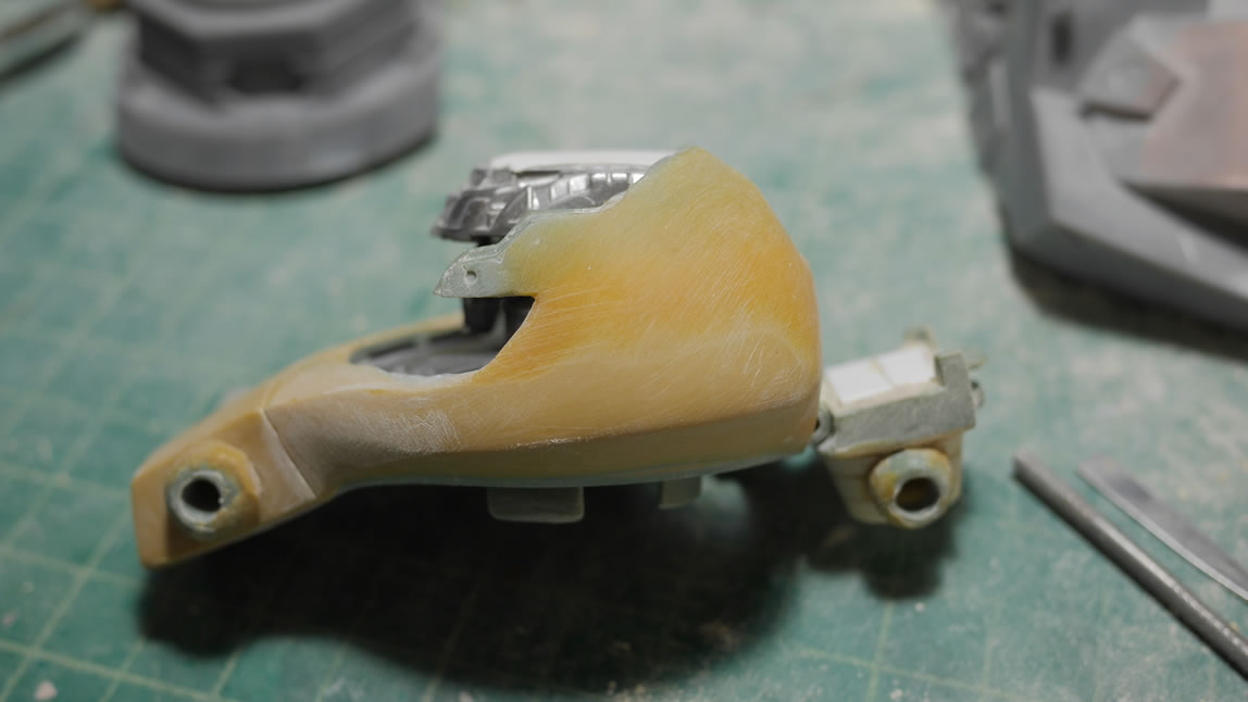
Time to get starting on the nose job for the Gouf. I measured the MG Gouf Custom’s nose and scaled it up to start gluing plastic and cutting excess plastic. The Gouf’s nose is flatter and shorter in height and longer in length compared to the Zaku. Some styrene is glued to the front of the snout to help extend that while keeping the vents. The top of the snout is trimmed off and the front piece is extended from the main nose piece. Bondo is used as the quick filler here.
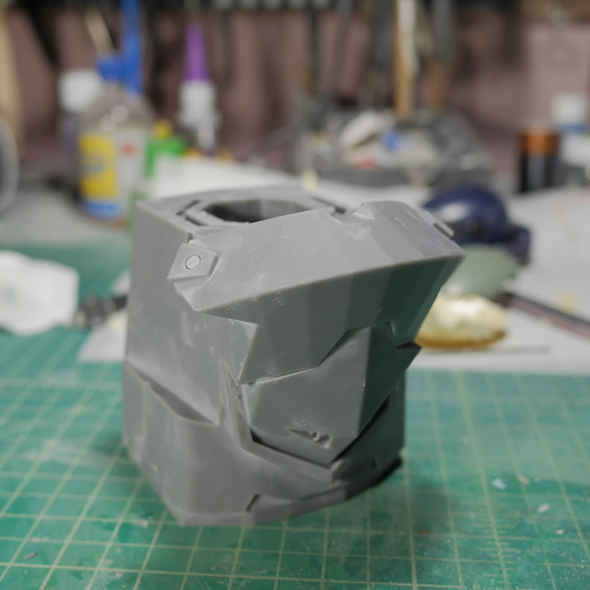
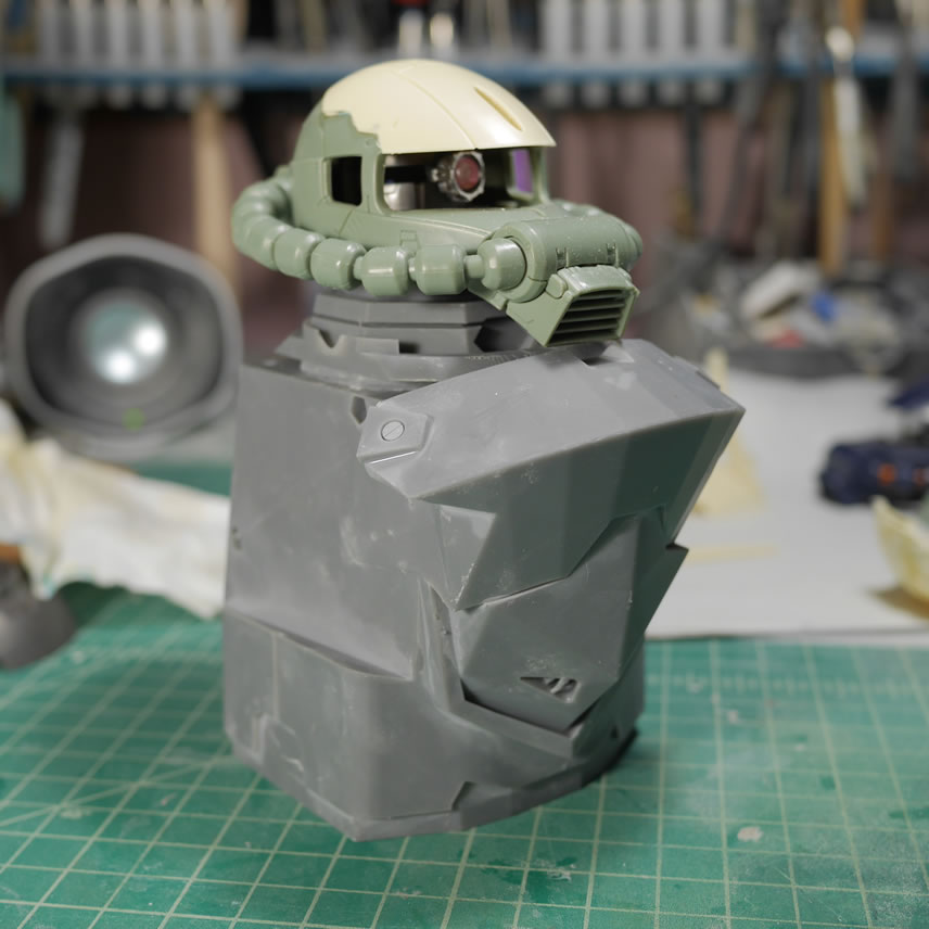
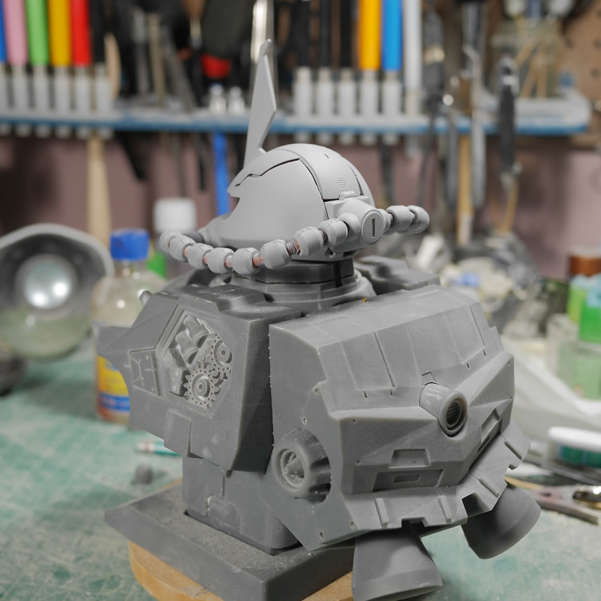
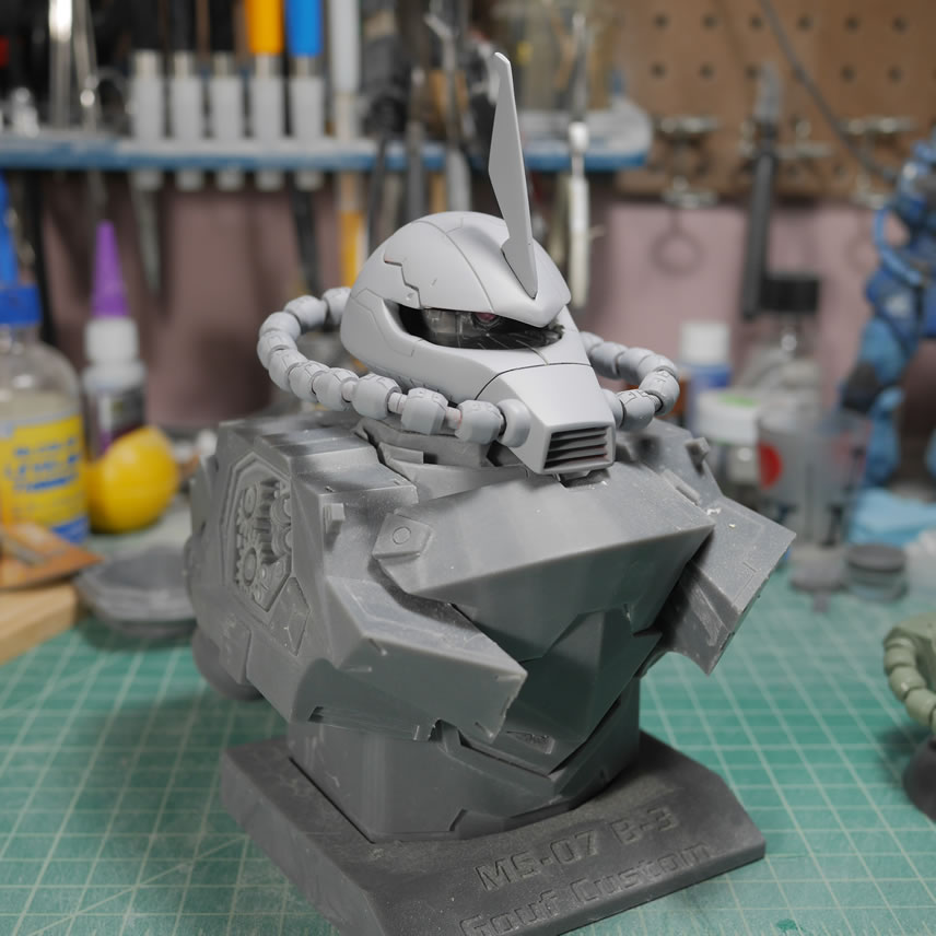
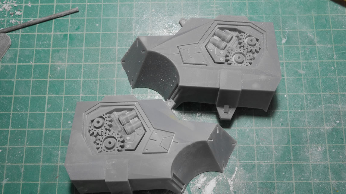
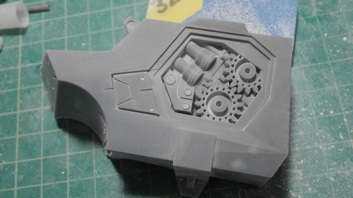
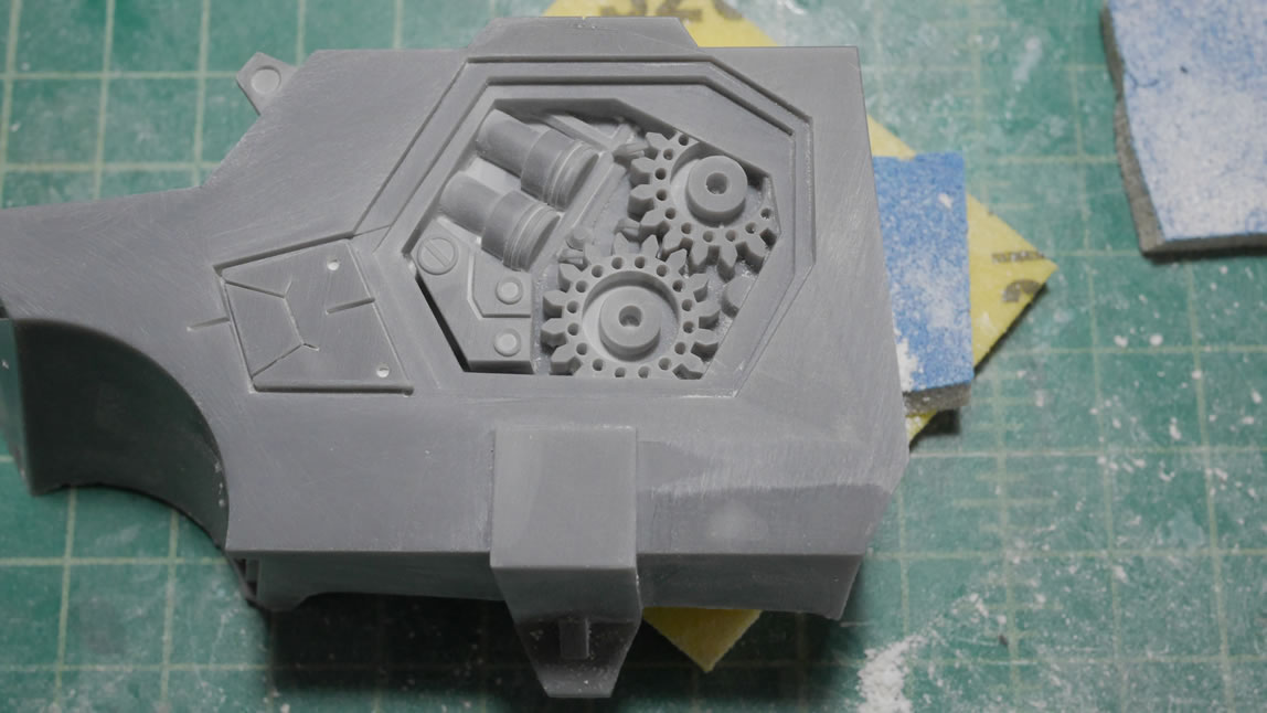
At this point, the new collar has been printed and it fits perfectly on both sides and the clearance between the Gouf head and the body is good. The first side piece of the chest is printed along with the backpack cable connection details finish printing after 29 hours. The parts are combined with the new collar and the side piece for the picture below. I designed some internal actuators and gears for the side chest details where the arms would effectively attach.
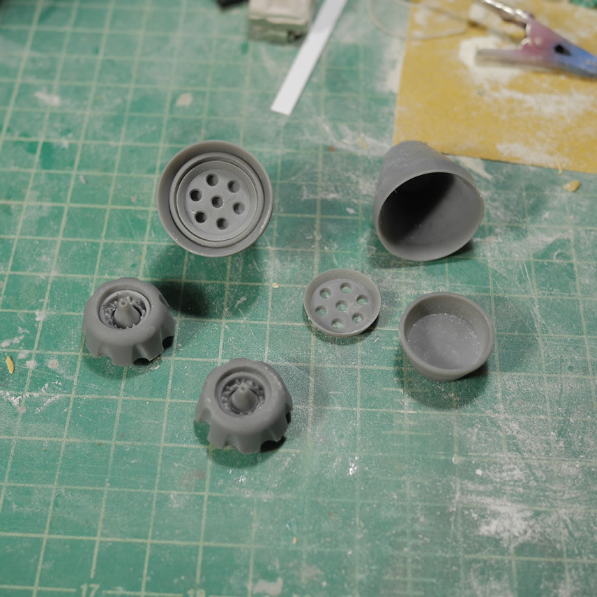
When the new collar was printed, I also printed out the thrusters and backpack cable attachment point. Since I will not have the waist cables, I still need the attachment point on the backpack. I did some guess work for the internal attachment point design. I think it looks pretty good and I got more practice with detail work in Blender.
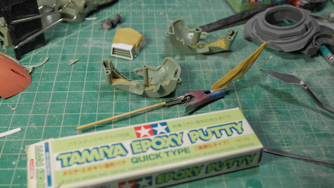
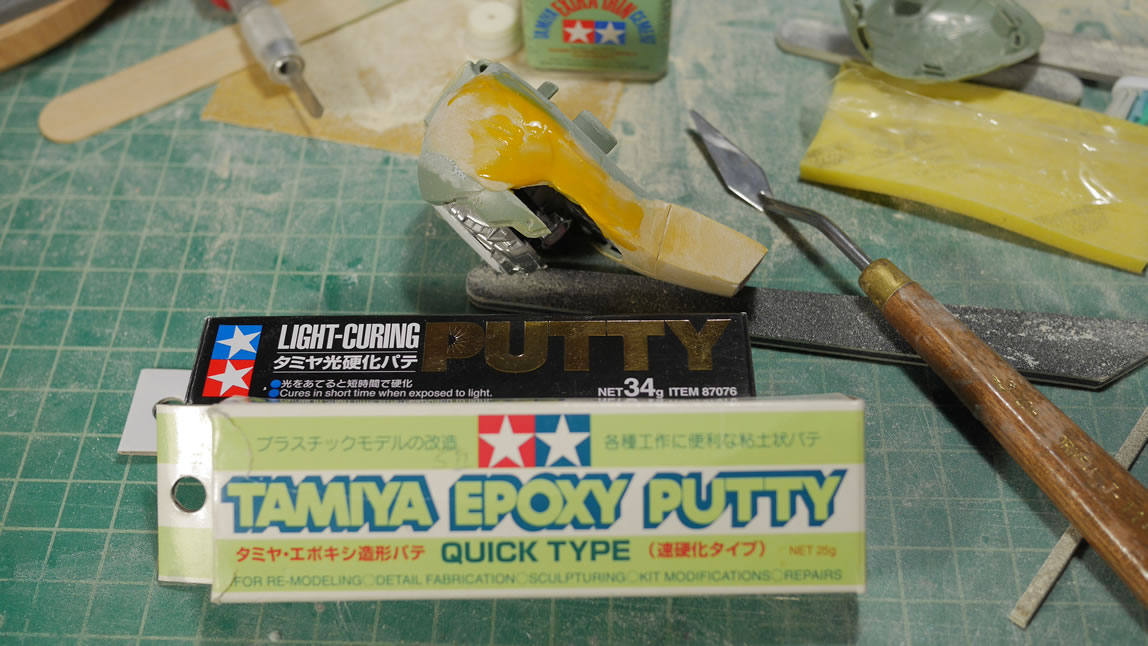
Epoxy putty is used to fill out the top and sides. Bondo isn’t friendly to scribing, but is a good cheap solution to filling. Epoxy putty is good for scribing but I don’t want to use that much of it as a filler.
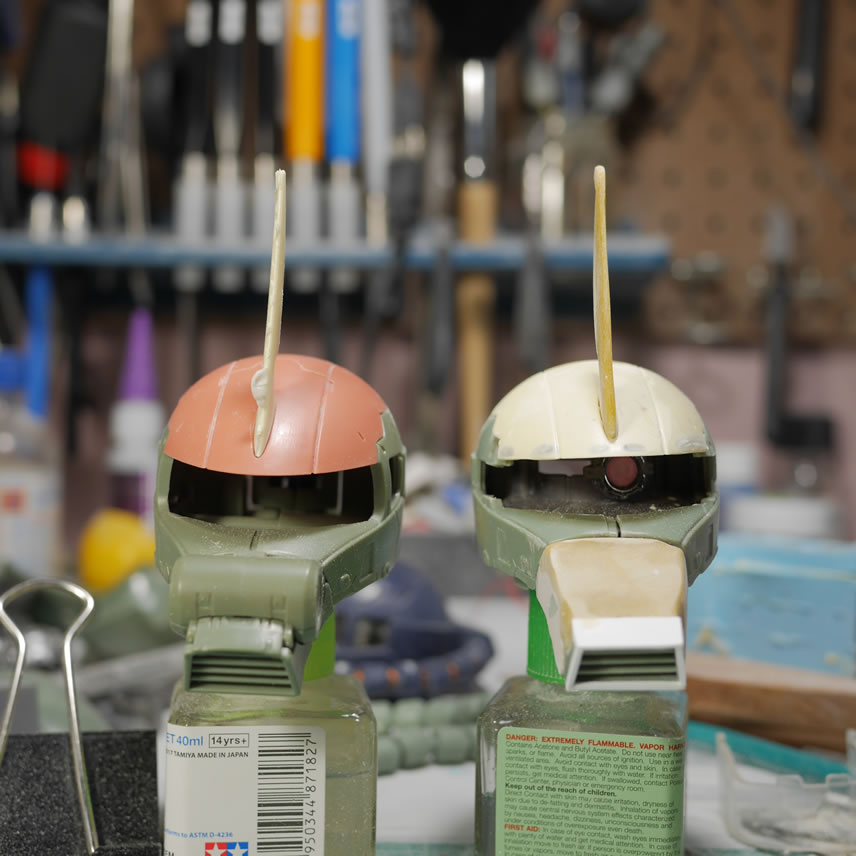
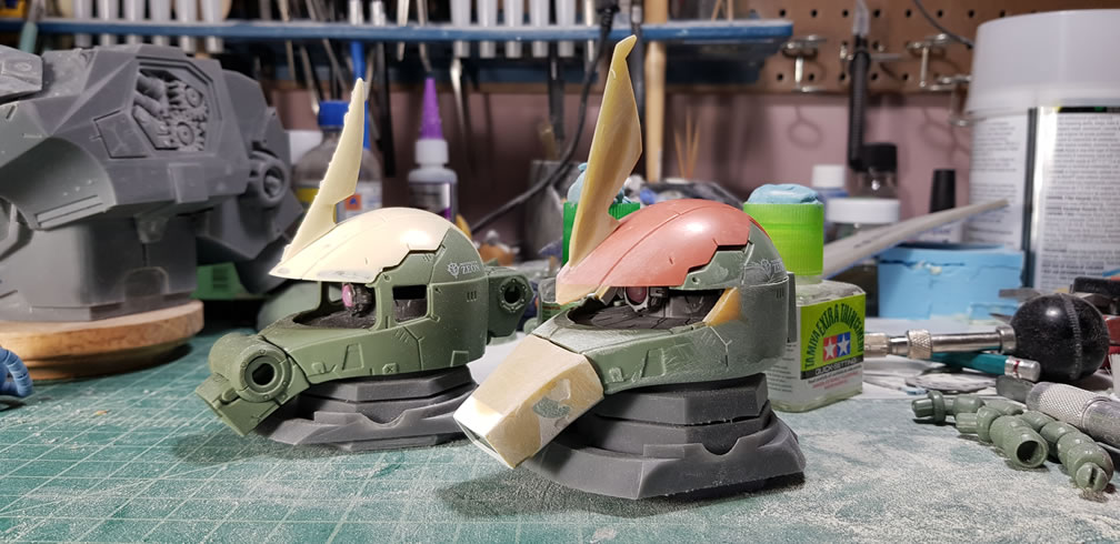
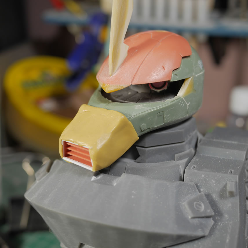
More epoxy putty for the resin commander fin copy and the internal sides of the Zaku head. The epoxy putty for the nose finishes up the filling and shape. The commander fin is completely different for the Gouf custom, so epoxy putty is used here to start building this up. The epoxy putty inside the head is for anticipation of the sanding work on the sides of the head to reshape it from a Zaku to No Zaku. Epoxy putty is used as a filler here since bondo will not work well for the future detailing once the plastic area is sanded away exposing the epoxy putty.
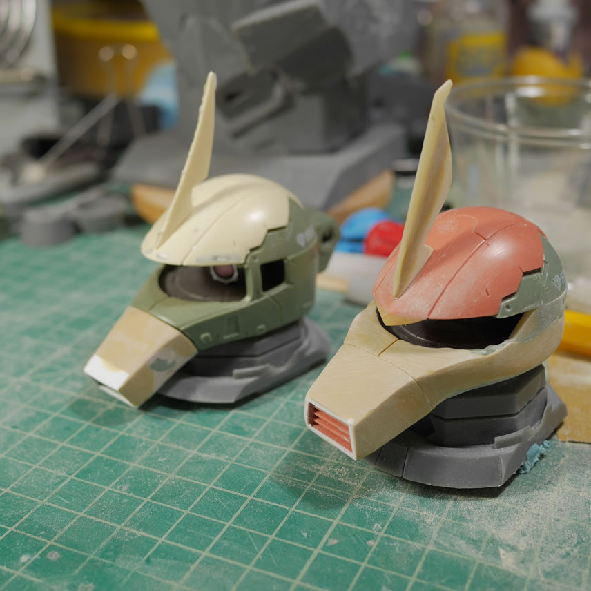
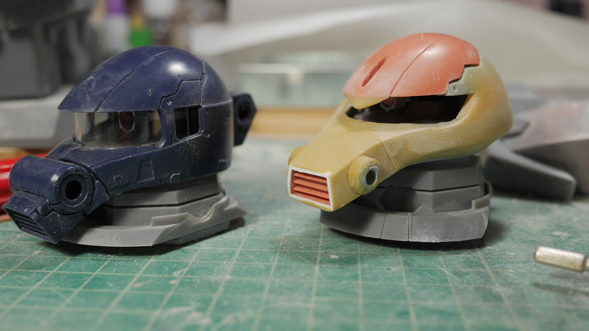
Some light curing putty finishes the build up progress for the commander fin. Here’s a comparison with the original Zaku head.
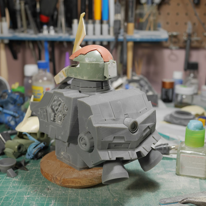
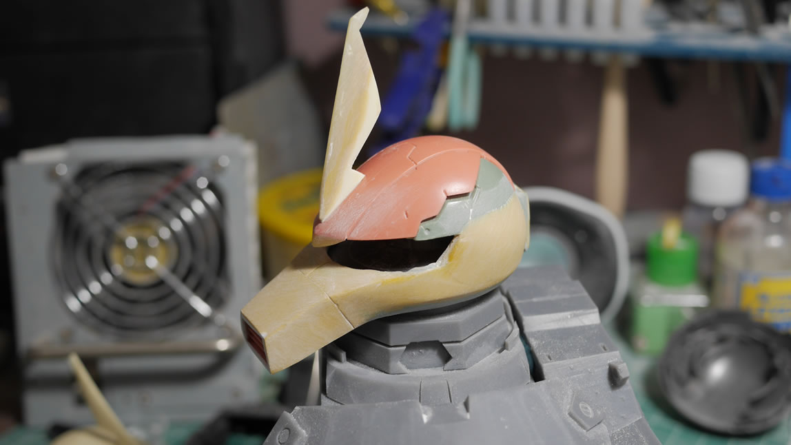
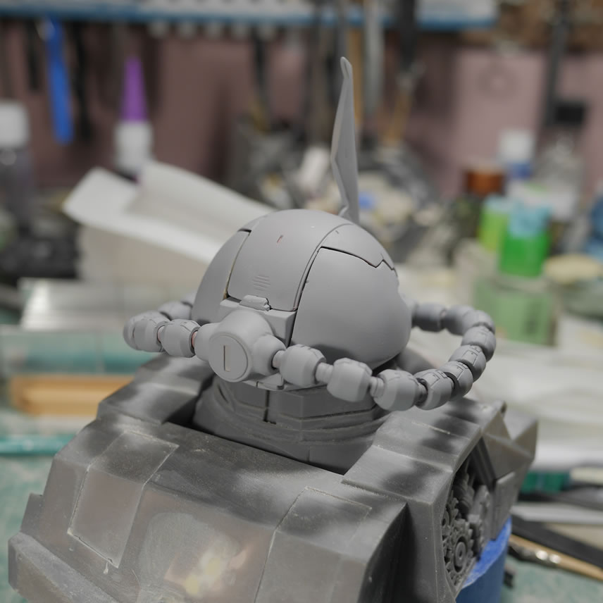
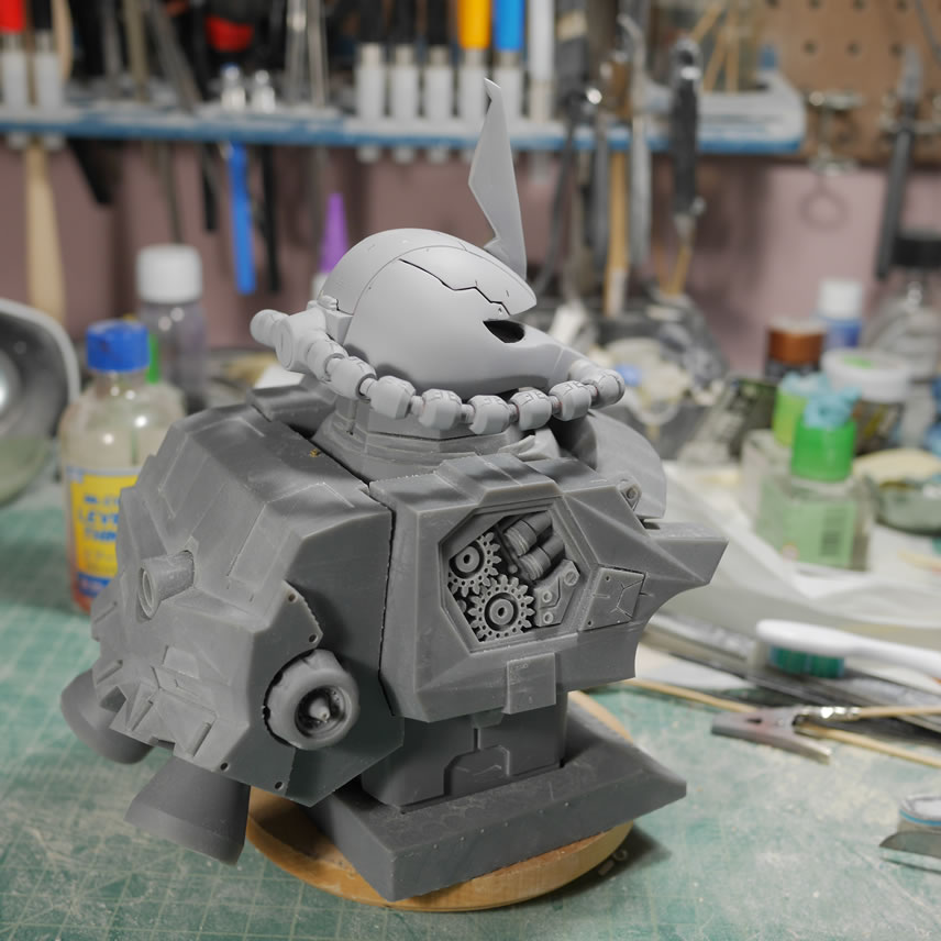
The backpack took 29 hours as well to complete printing. The thruster bells and cable attachment detail are attached with sticky tack and the bust is 1 piece shy of completion. As of this posting, there is still another 3-4 hours left in the estimated 20 hour print. I added the legs back to the NeoGrade Gouf Custom for a more complete comparison between the 1/100 and the bust. If you look carefully at the back area of the gouf’s visor you should see that I’ve glued in some styrene. The Gouf’s visor differs from the Zaku in that this area is angled and not a rectangle shape. The styrene is glued in as support.
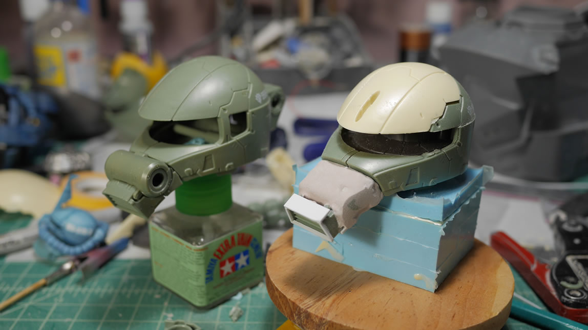
Since I have a copy of the commander head piece, i can get to modifying the original part. Light curing putty is used to build up and shape the sort-of-widow’s peak on the front of the Gouf’s visor. Light curing putty is also applied to the back of the visor areas using the glued in styrene strips as structural support. Sanded down, the head is starting to look more and more Goufy.
Here are some more comparison shots with almost all the pieces of the bust printed. So much for a quick and dirty little Zaku Exceed Head project. This may even turn out to be a conversion kit. This will depend on how much it’ll cost to mold and cast all these. I’ve never molded/casted anything of this size so more unknown territory for me.
I haven’t posted an update in a long while since I’ve been extremely lazy in the past few weeks. I’ve been suckered into playing GBGW (Gunpla Battle: Gunpla Warfare) on my damn phone. *cough*E4AKNYNR6*cough*. But that has slowed down because energy recovery at higher levels takes some time, and I’m not giving Bandai any more money than I already give them.
August 26, 2019: Back to working on the Gouf Custom project
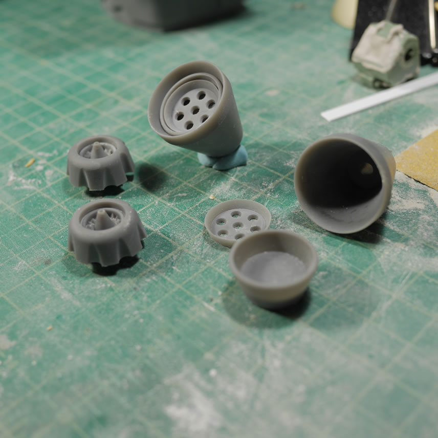
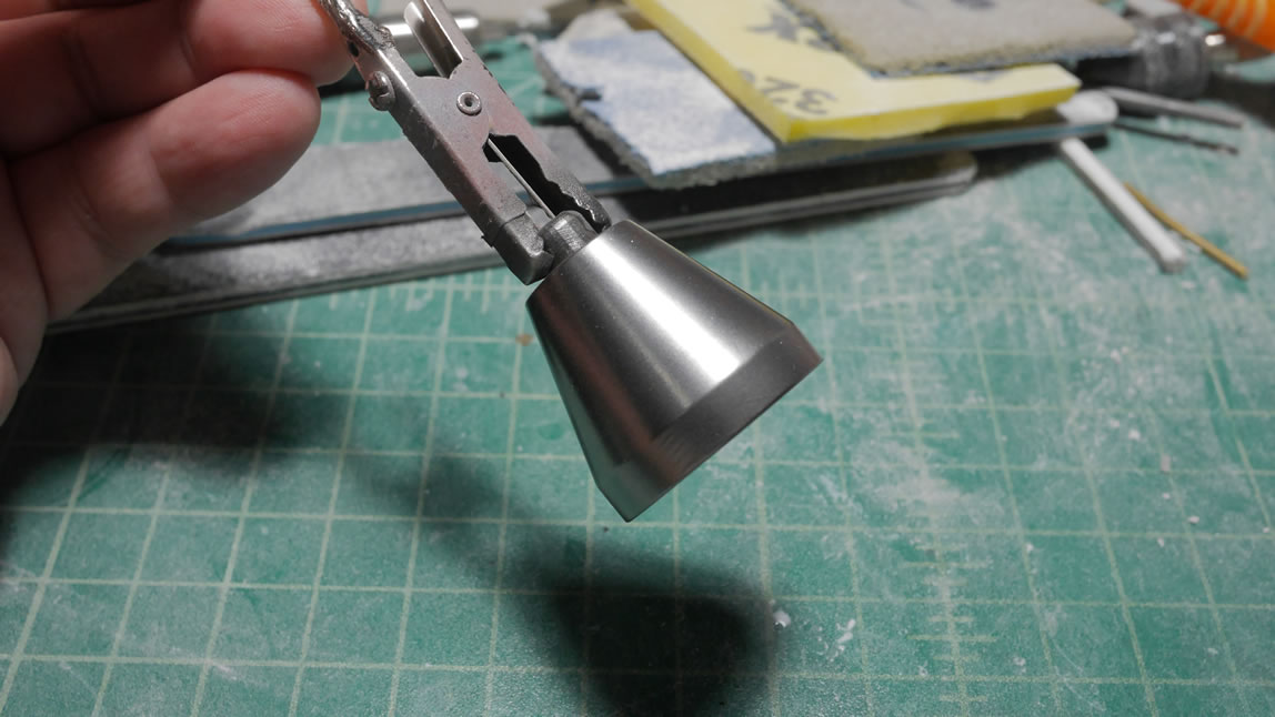
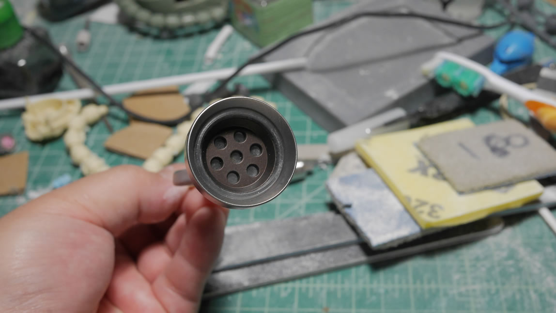
When I last posted about the Gouf, I was still in the process of getting all the parts printed out. Going back to the thruster pieces, I made a mold and casted a clear copy of the middle thruster piece. Assembled, the clear piece is sandwiched between the round detail bit and the main thruster housing. This is where things will make sense as to why I printed the thrusters in 3 pieces.
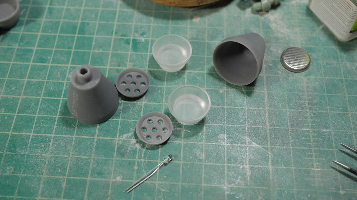
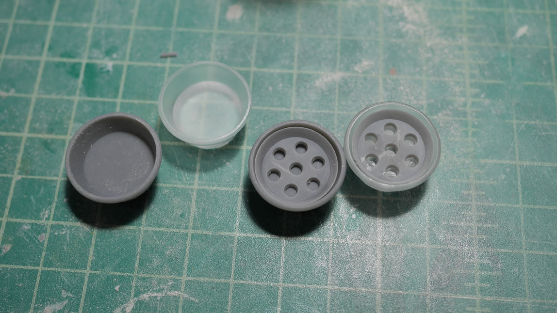
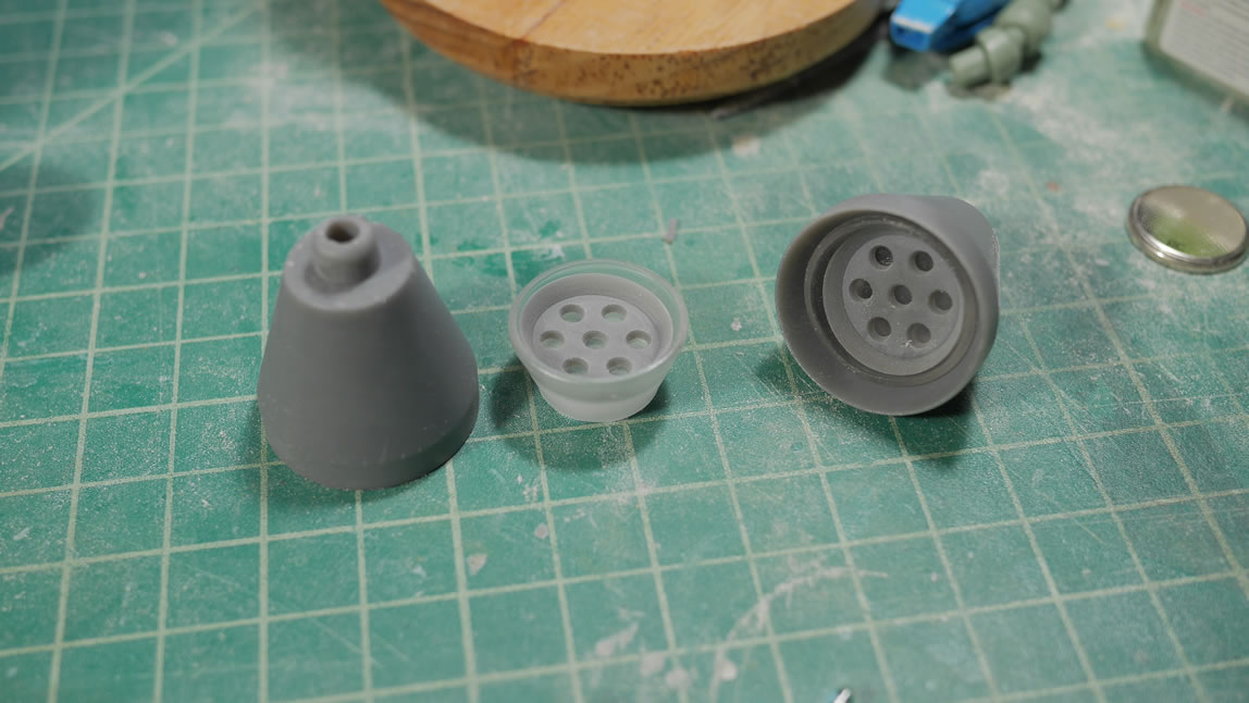
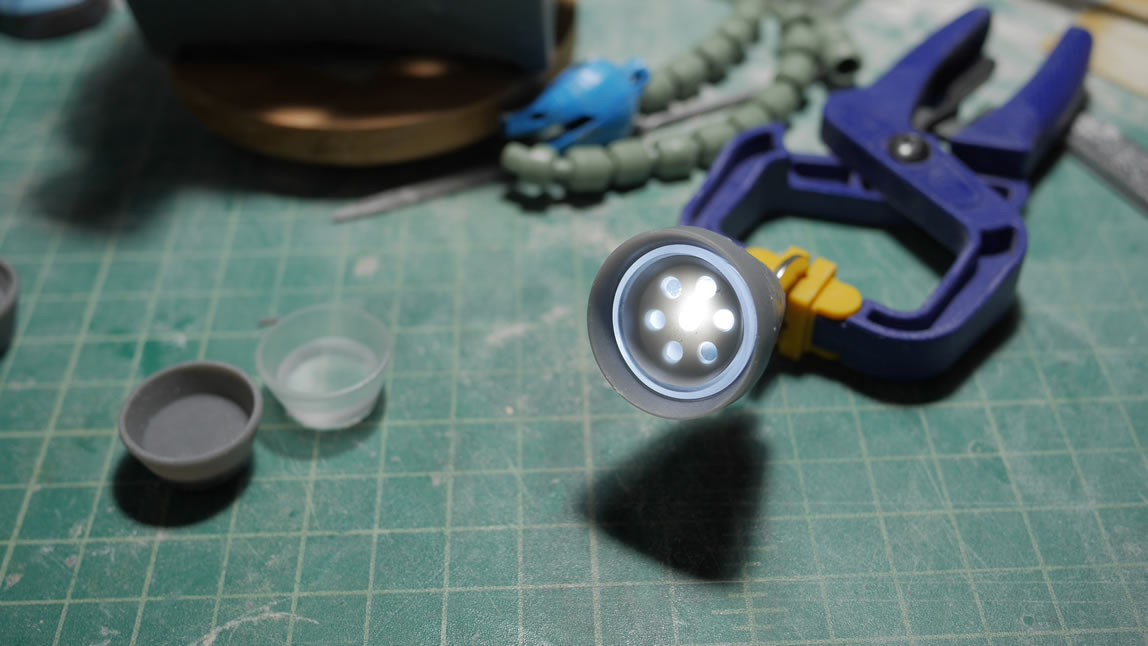
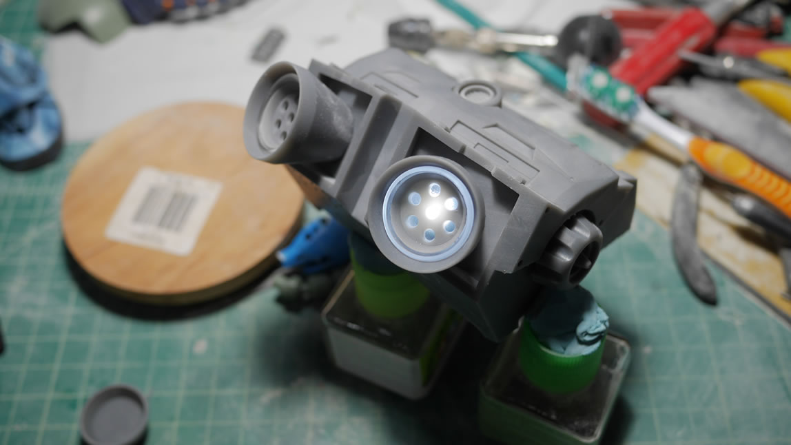
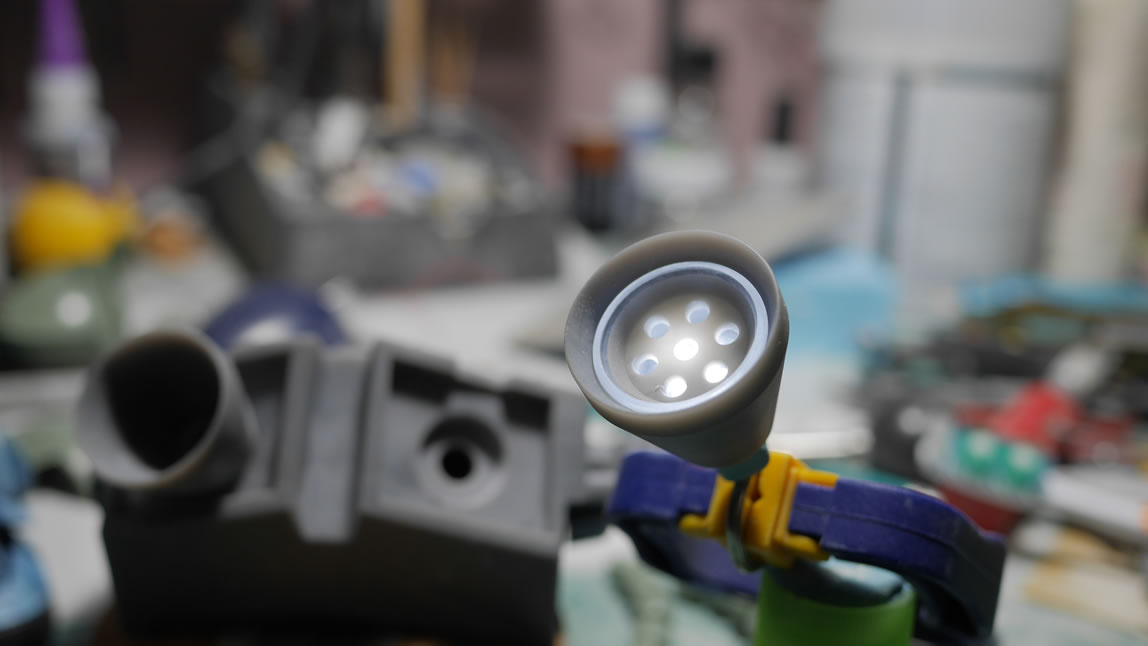
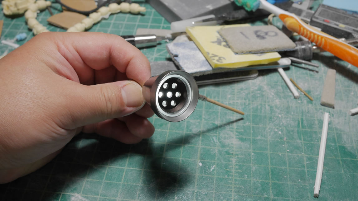
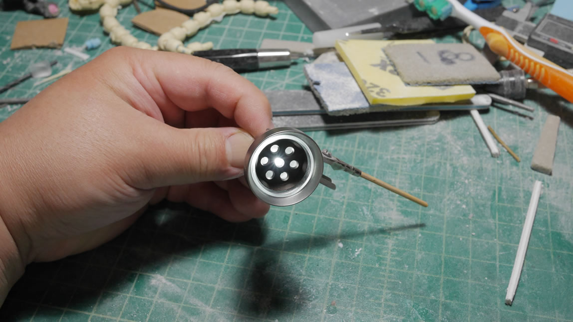
With the middle piece clear, I can add an LED into the thruster and have a designed light pattern. Here are some pictures with a few different angles to show off the designed light. The clear middle piece creates a halo effect.
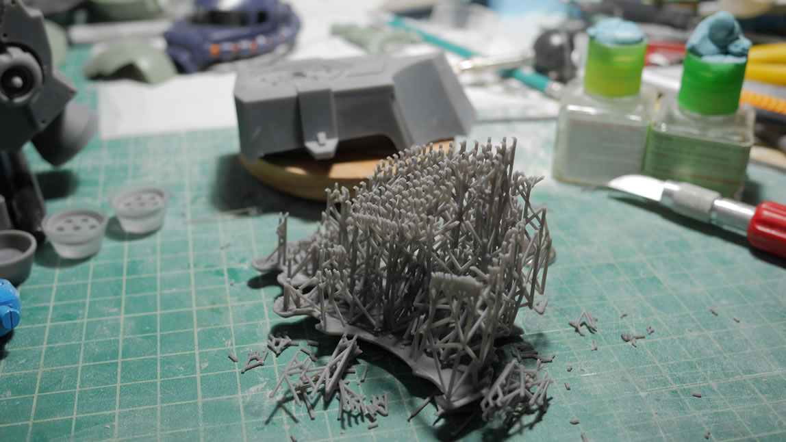
The last piece of the bust finished printing. Look at the amount of support materials required to print. After the post print clean up work (soaking in isopropyl alcohol, and additional UV curing), I can get to removing the part from the support and raft.
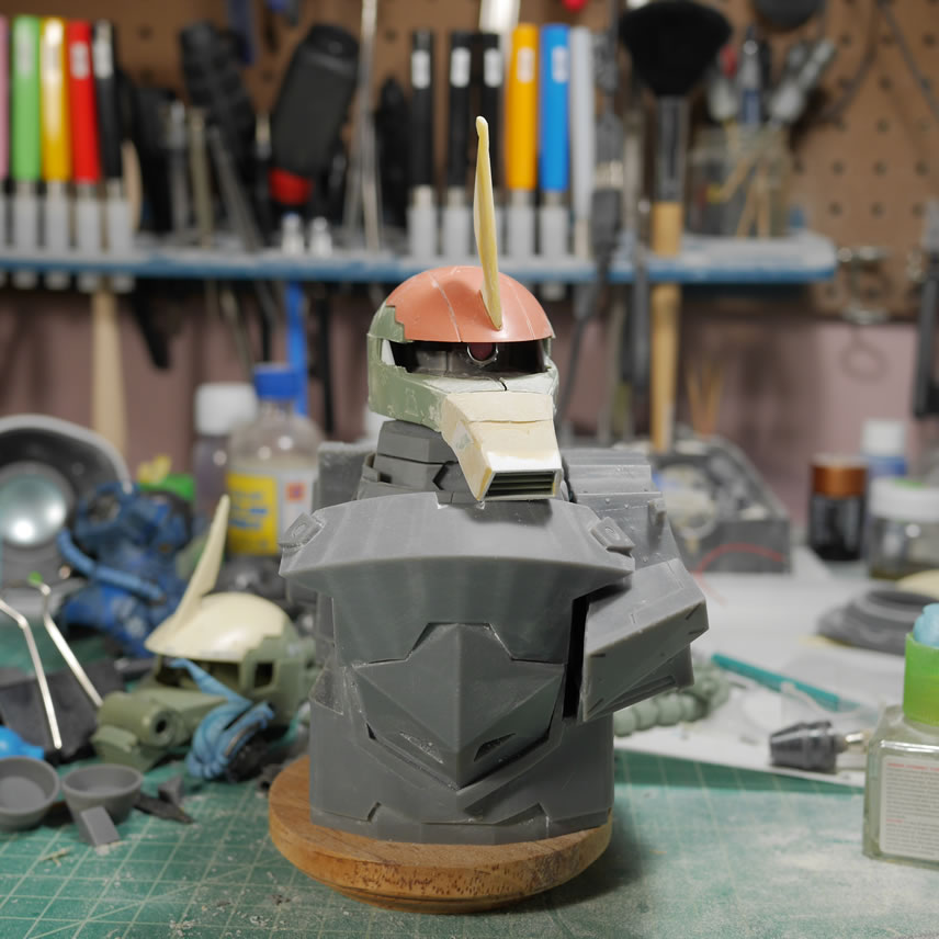
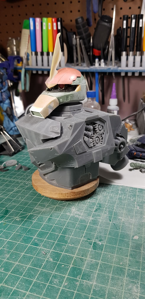
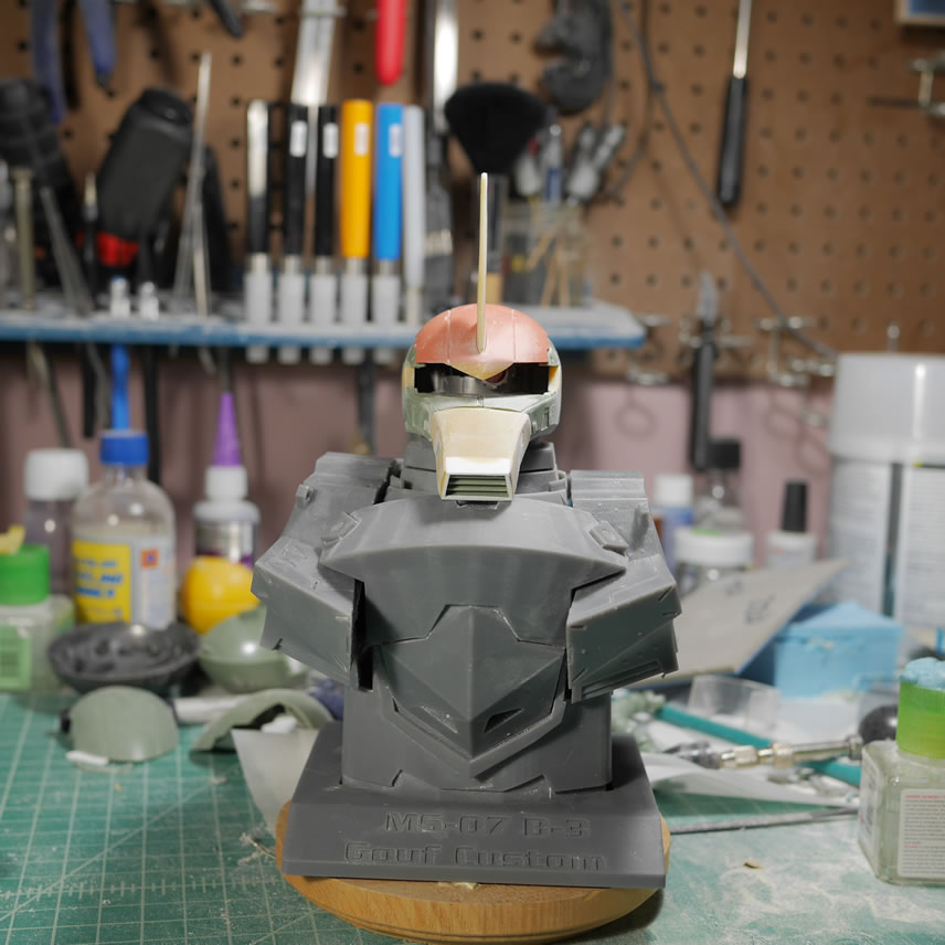
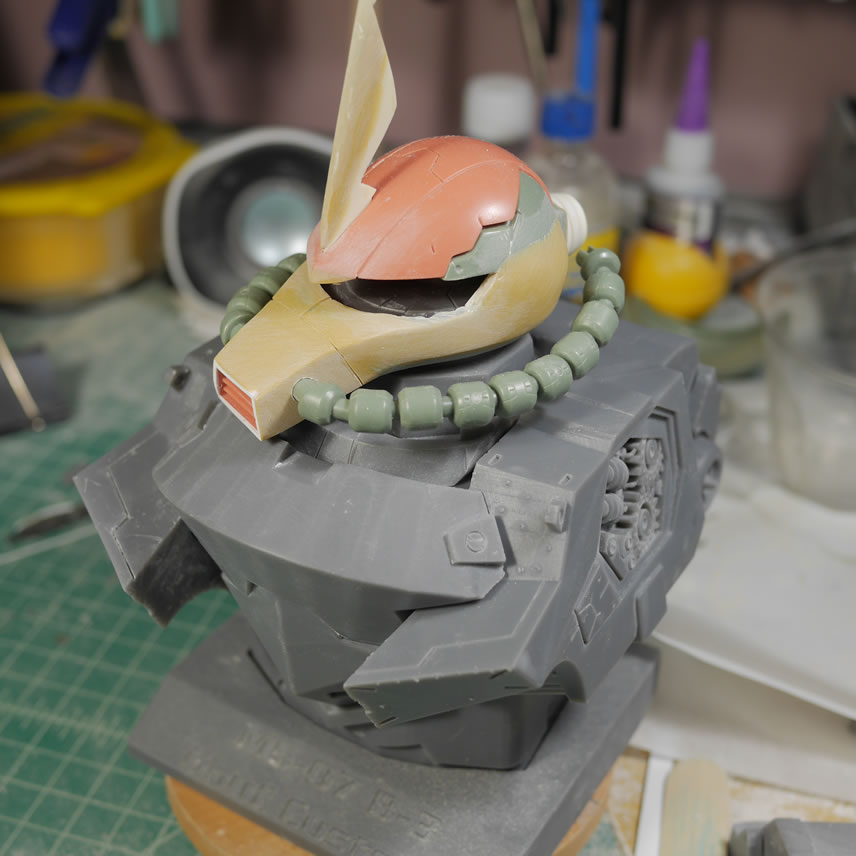
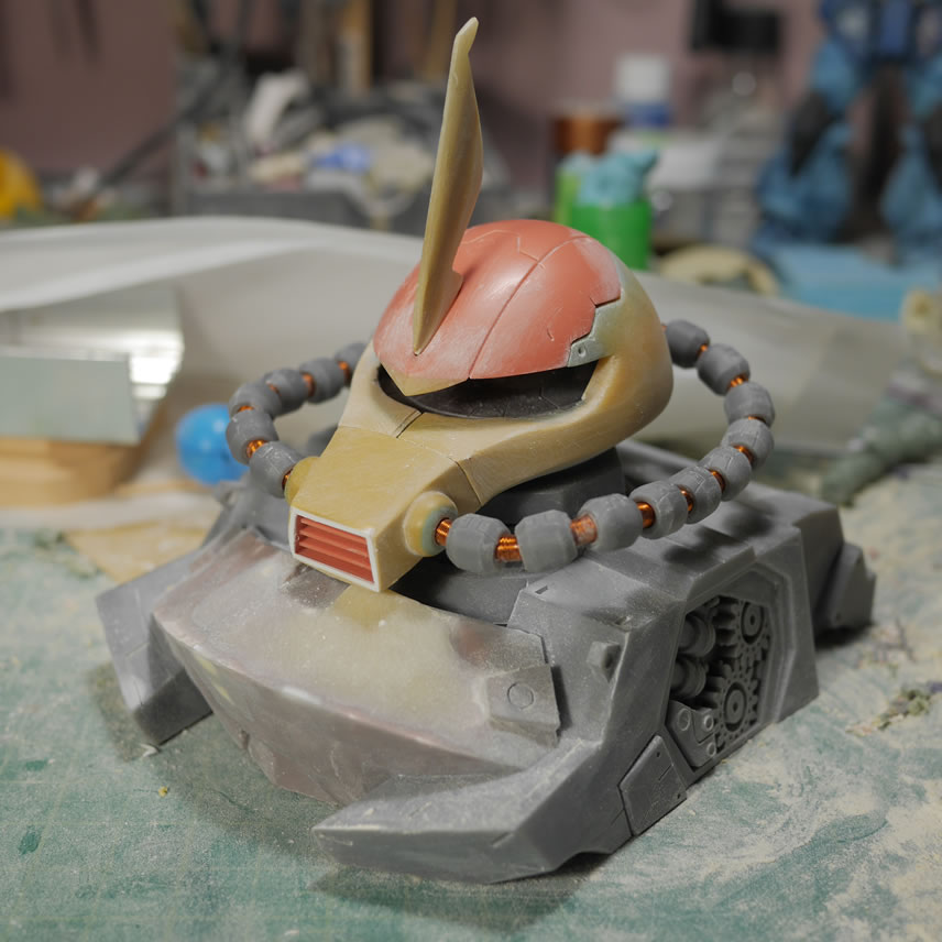
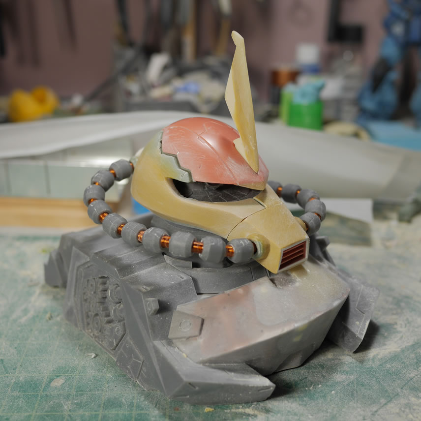
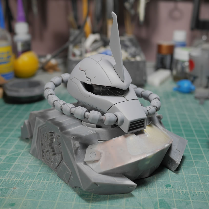
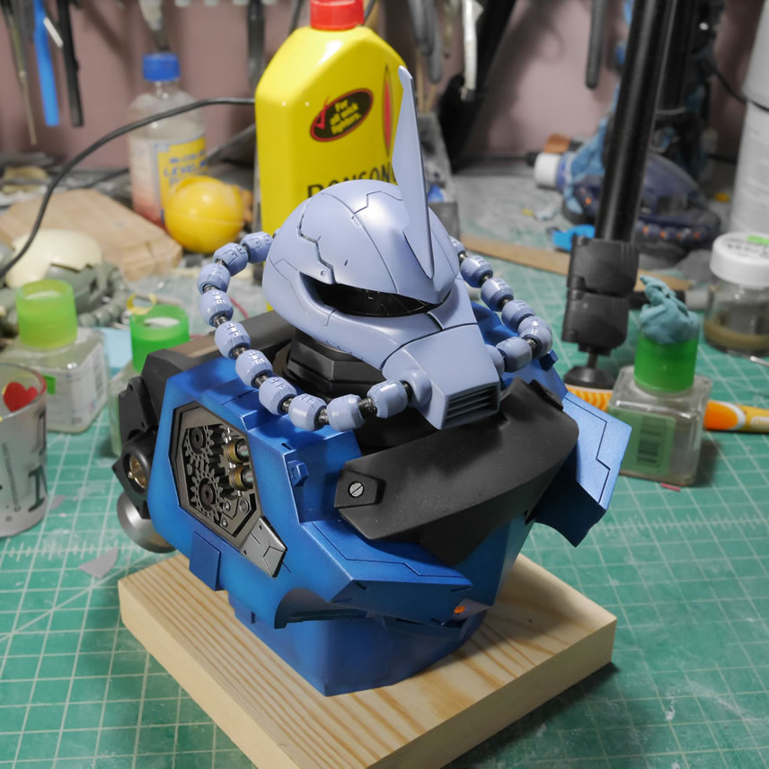
Here is a test fit with all the parts of the bust and the work in progress Gouf.C Exceed head. At that time, the head may look too small for the bust piece, but it is a visual trick since the head doesn’t have the cables yet. If I swap out the head with the regular Zaku Exceed head with cables, the balance is back and it looks in correct scale. I need to do something about the Gouf.C nose….
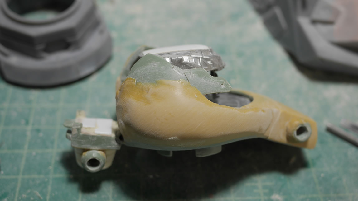
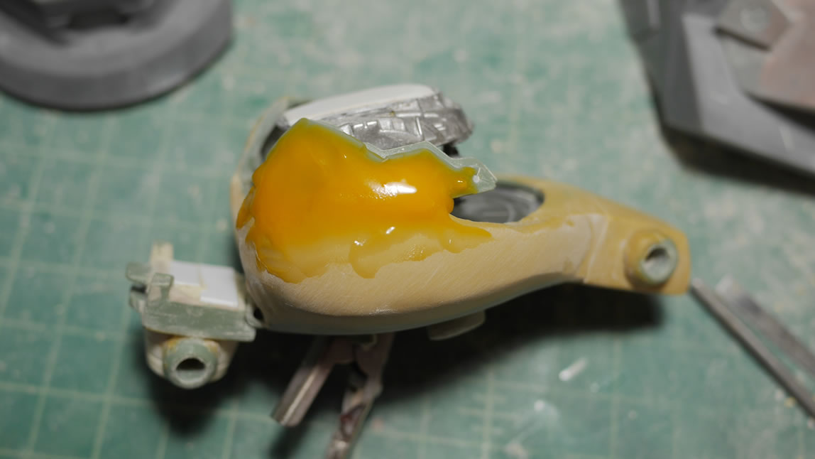
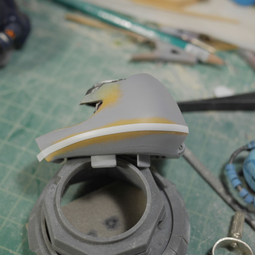
Scrapping the first attempt at the Gouf.C mouthpiece/nose, I grabbed another base nosepiece and started from scratch. Glued some styrene to lengthen the vents, then glued the two nose pieces together while adding a little bit of length. The excess is just cut away. Once that is done, I did a quick fill with bondo and let that cure. The bondo is slightly sanded to get the initial shape and add surface area for the next putty session. Epoxy putty is added to encapsulate the bondo and work as the secondary shape. Epoxy putty is easier to scribe than bondo, but more expensive than bondo by volume, hence the polyester filler than the epoxy. The different color tones in the putty show the bondo, the epoxy and the light curing putties. Each putty has its own unique usage in my tool box, so for projects like this all three and sometimes more (different brands and styles from the basic three mentioned above) are used.
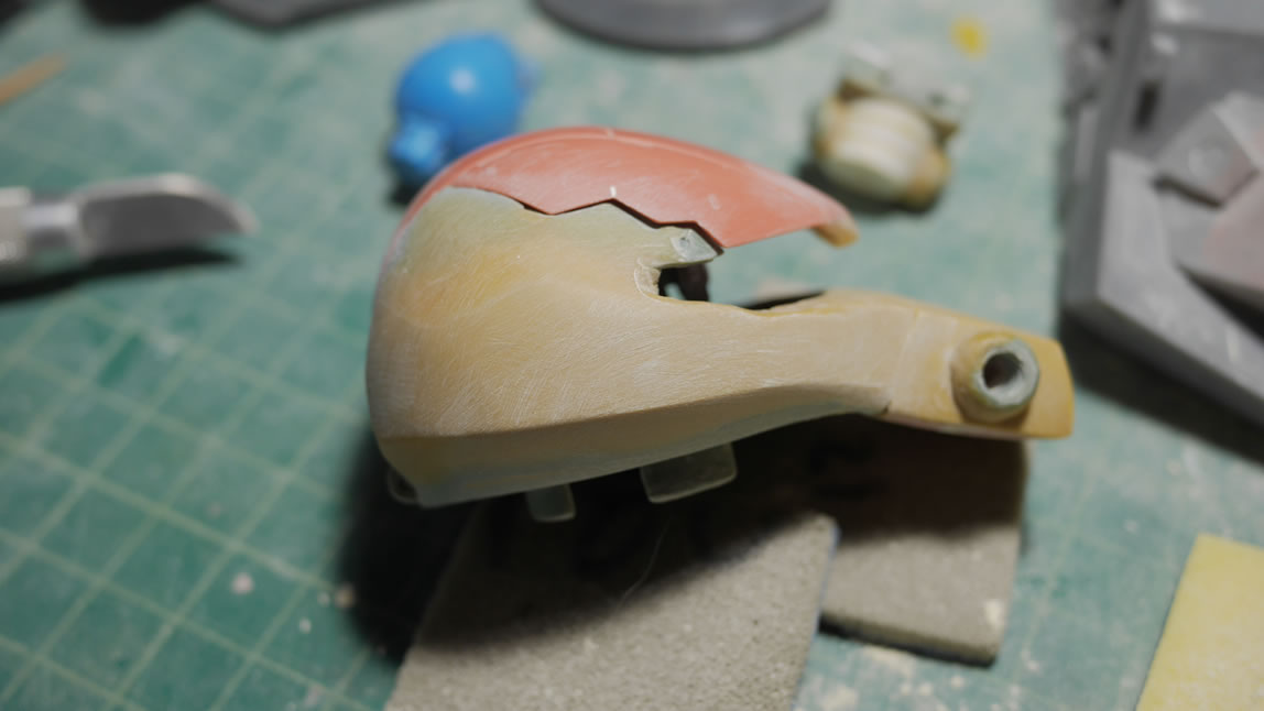
The initial sanding and shaping looks better than the original attempt. Sometimes the folks on the internets are correct and since it’s only plastic, anything can be fixed… or in this case, just rebuilt from scratch.
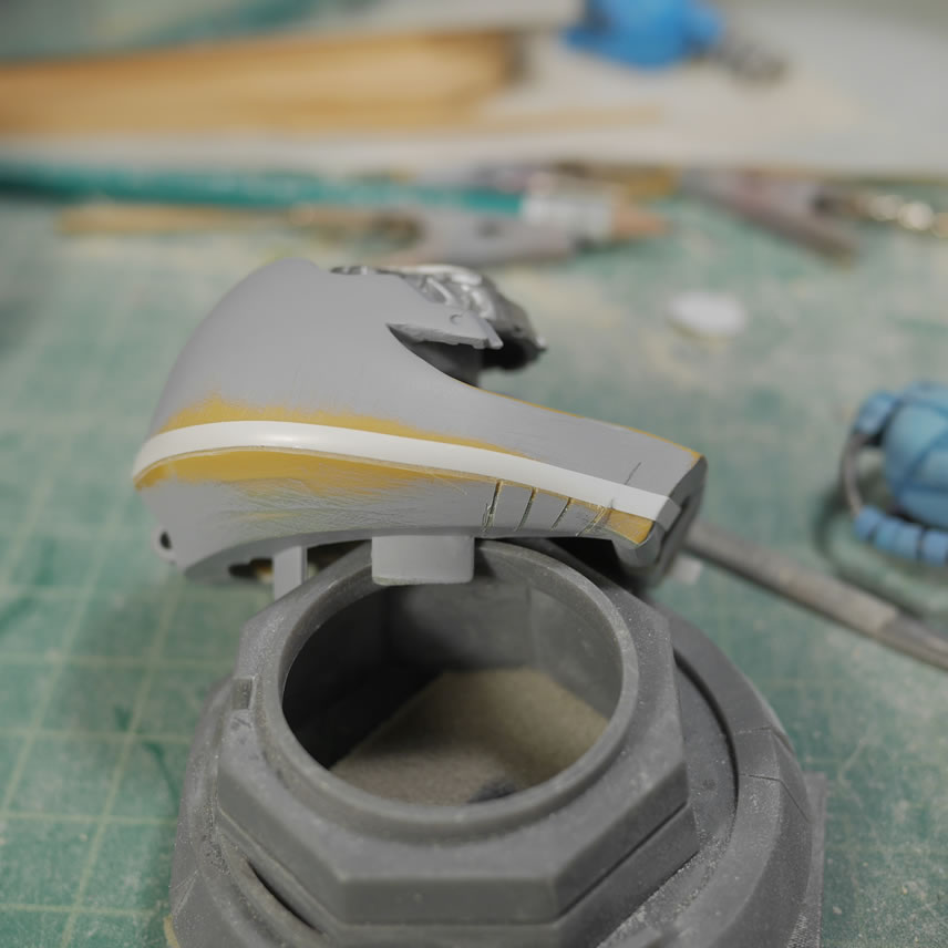
The epoxy is shaped and sanded. Light curing putty fills in some of the uneven areas and transitional areas between the epoxy and the bare plastic. I like using the light curing putty here because the layers are thin and allows for very quick work between putty and sanding sessions.
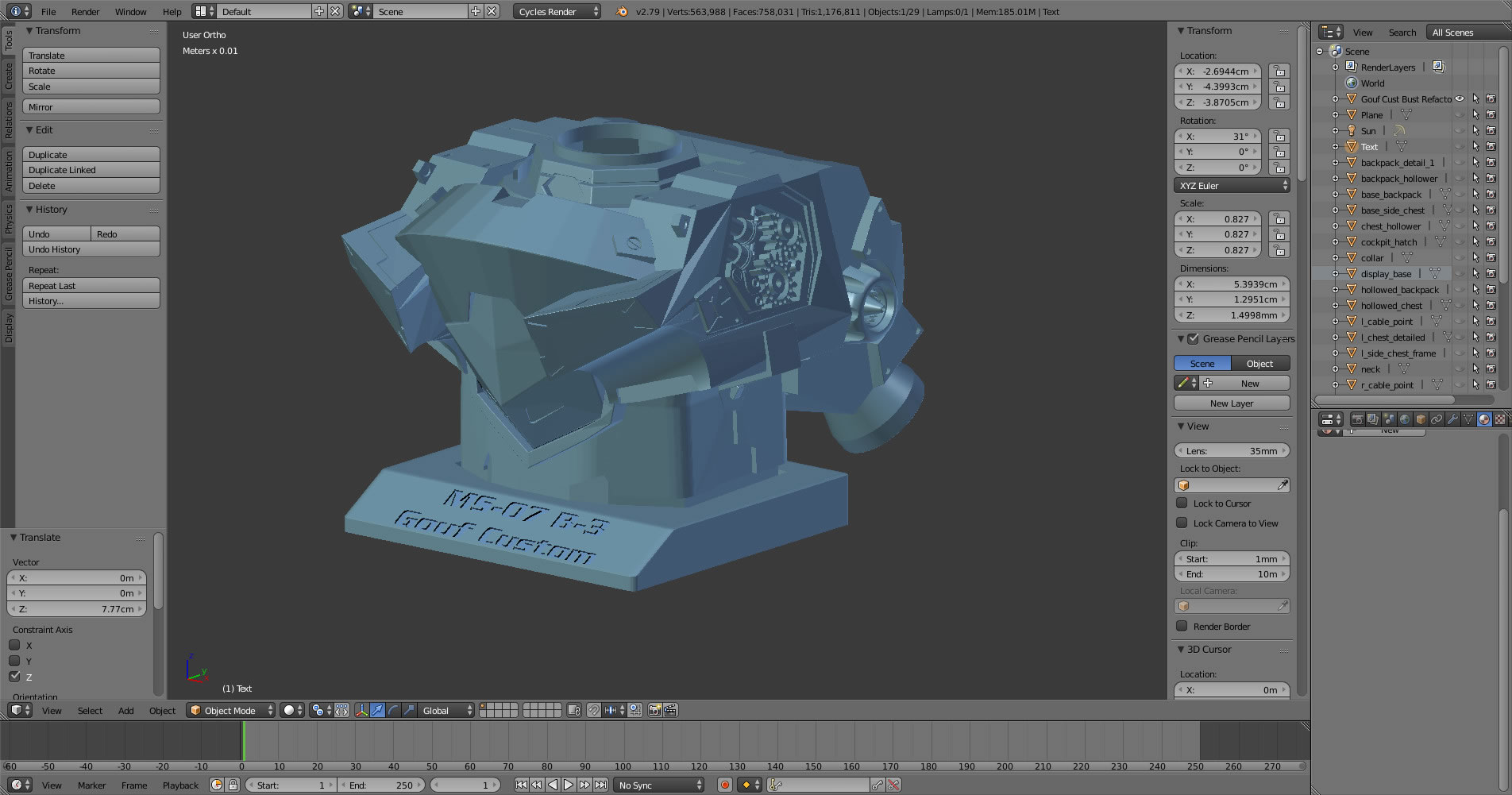
My initial thought was to kit the whole bust. But the damn thing is HUGE and I don’t think I could reasonably sell them. It would take quite a bit of investment to mold and cast all the pieces. Especially since the major pieces are so large. So I returned to the project in blender and refactored it a bit. I combined the 4 main sections and then cut it so that I only have to top part of the bust. It should be enough to recognize it as the Gouf Custom’s upper torso and making a mold and casting this will be much more manageable and cheaper for the end customer. But I will still work to clean up the whole bust with molding/casting in mind. But for now, I have a backup plan.
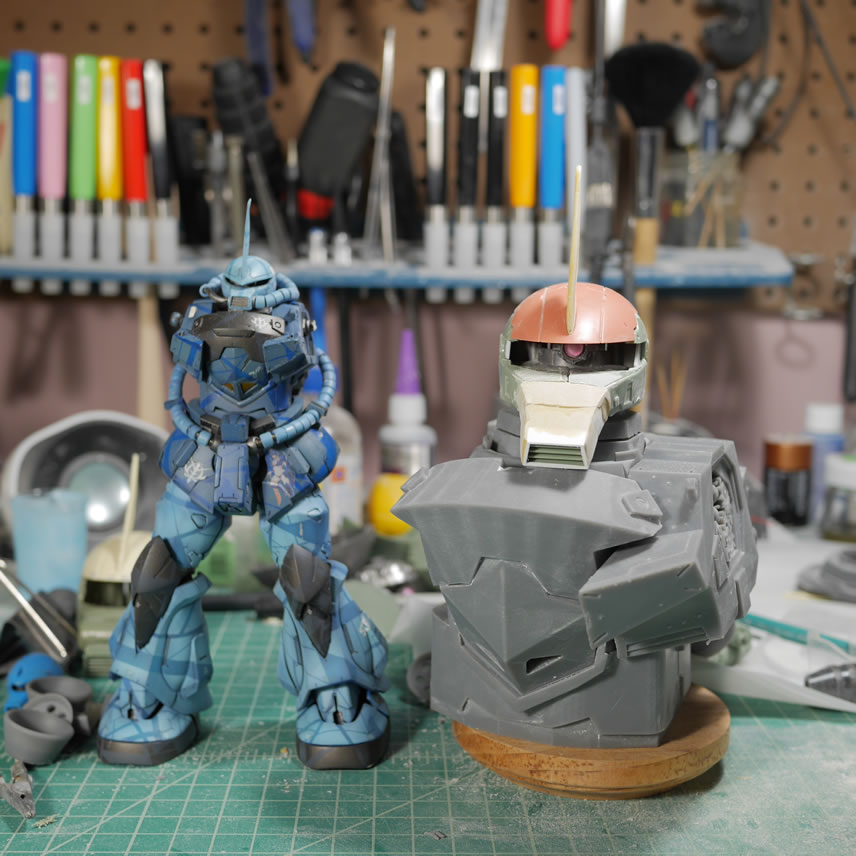
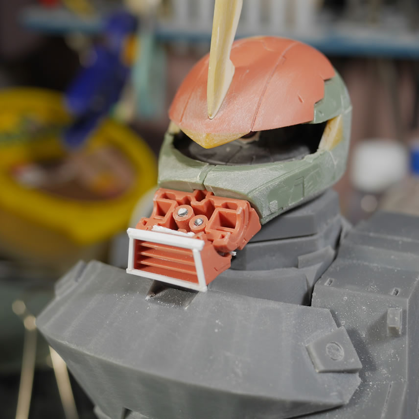
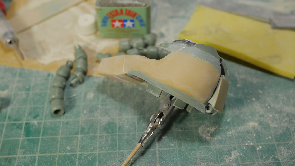
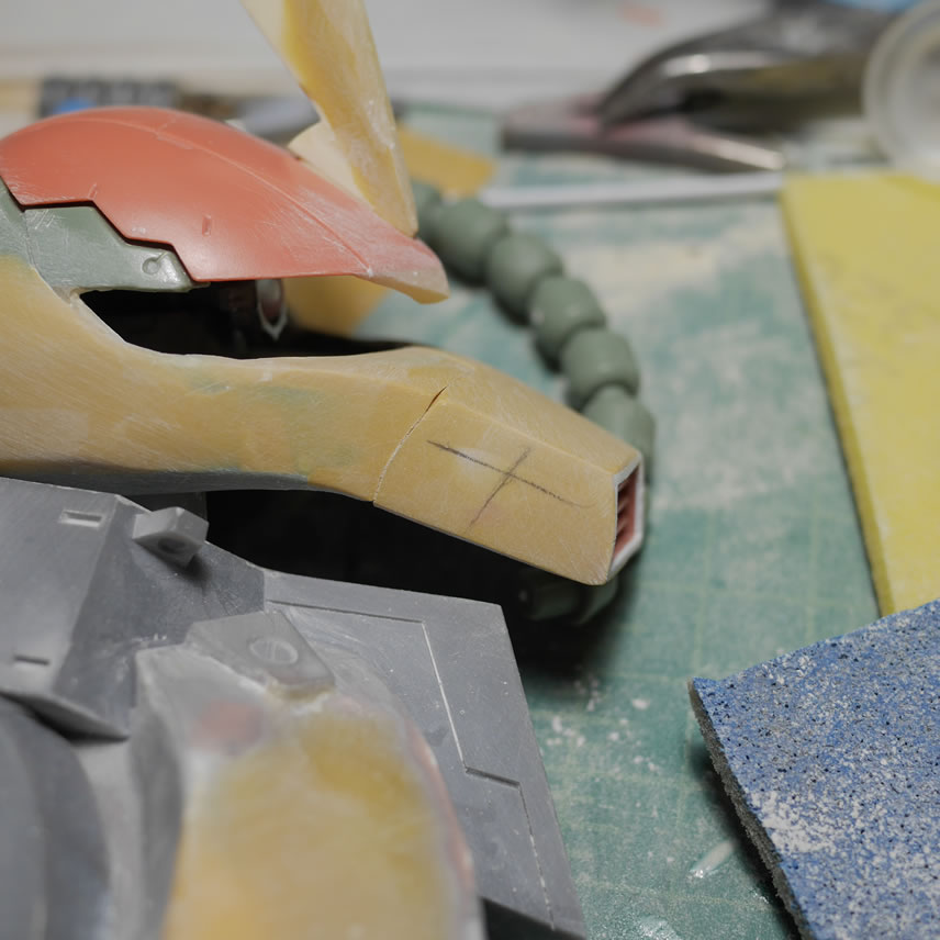
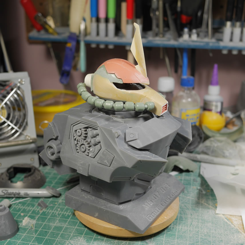
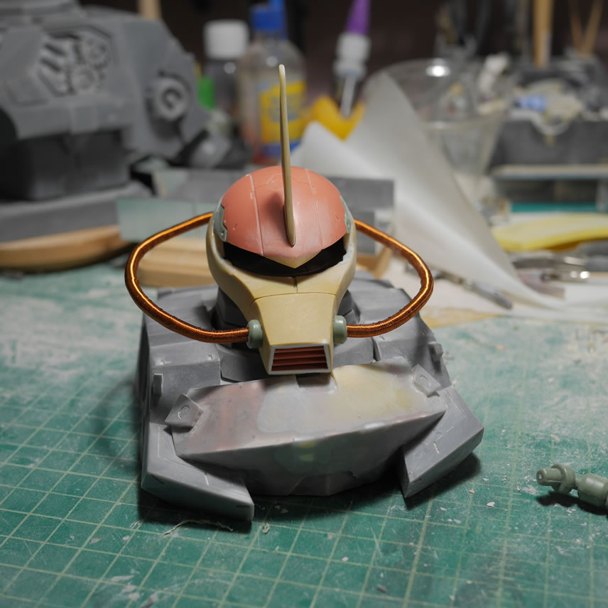
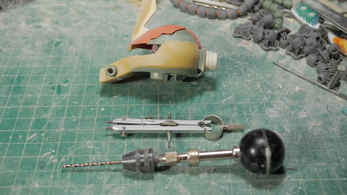
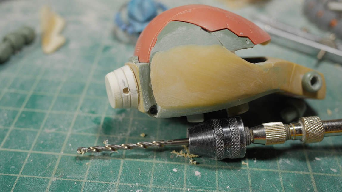
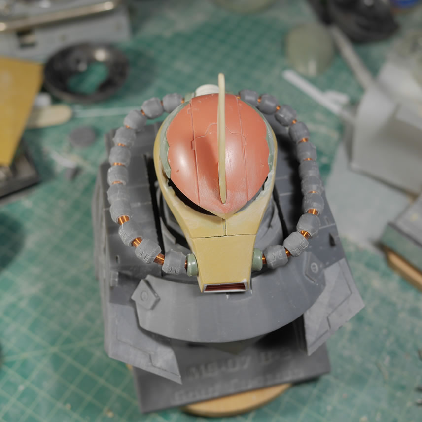
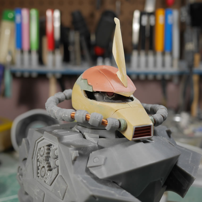
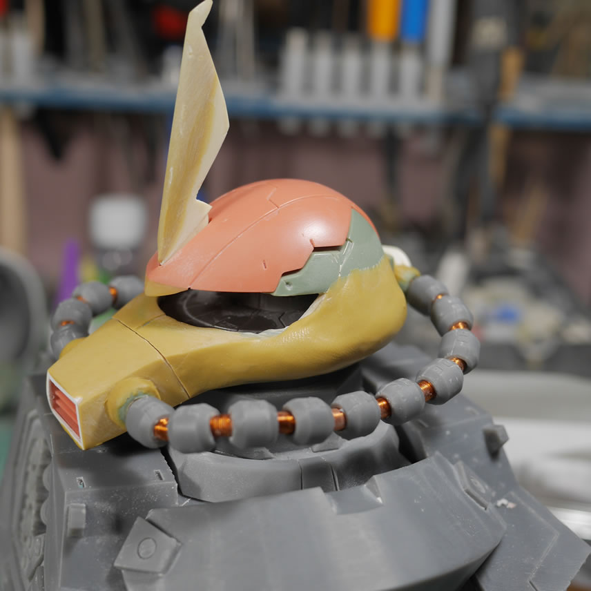
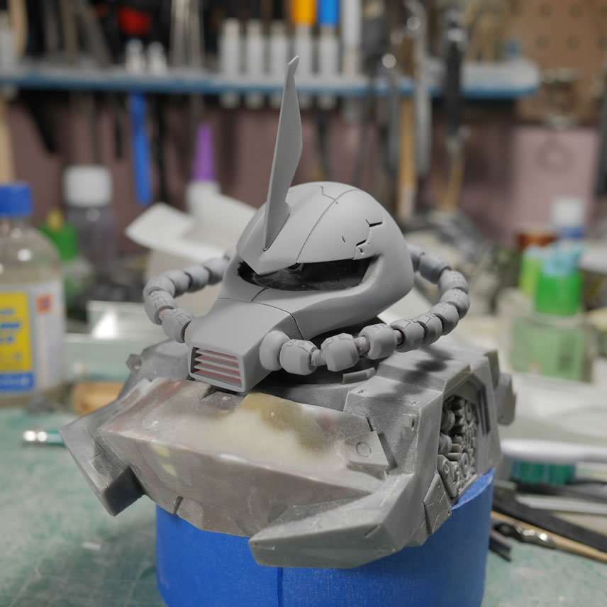
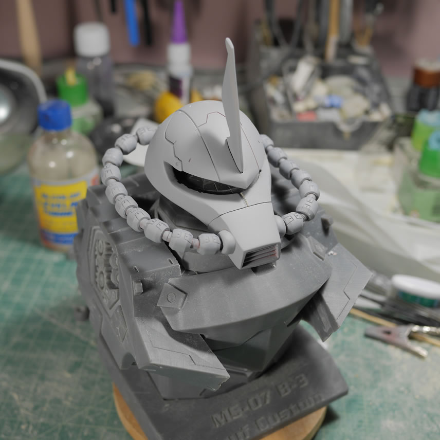
Since the nose is looking pretty good, I can get to working on the head cables. First step is to mark off the new attachment area for the cables to the nose piece. A drafting compass is used for more precision in marking the areas on both sides of the nose using references along the edges as guides. Holes are drilled and the stock Zaku cables are lightly shoved into the newly created sockets for a quick test fit. Both chest pieces are tested out and the cables really do fill out the head and validate the scaling. *wipes sweat built up over the past few weeks when someone online pointed out that it looked completely out of scale with one another*
I snapped a couple of more angles to get a better feel and to check the alignment. Everything here is hand done so it is VERY easy to make a mistake and throw everything off balance. So far, so good.
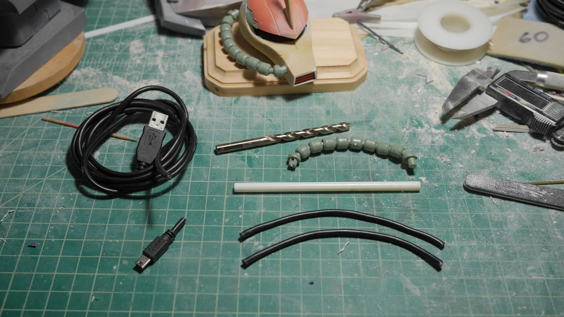
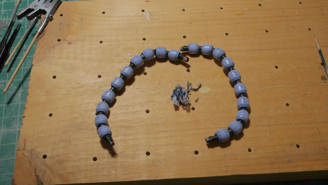
The Zaku’s original cables are 3 pieces and the shape is static to the point that there are only 2 points of articulation to shape the cable bends. This combined with the fact that they don’t fit the modifications done to the head means new cables. I looked around my workshop for some suitable objects as base cable materials. In the past, I just used some shielded solid wires as the base. But since this is several times larger than your typical 1/100 or 1/144; I needed something thicker
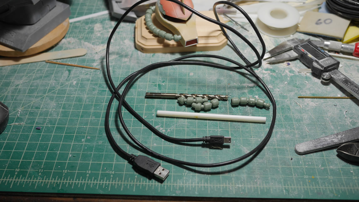
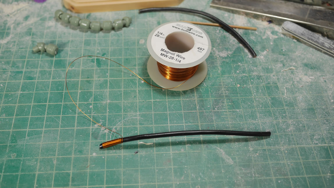
The cables are wrapped and I can test fit the base cable and start shaping them to the Gouf.C’s cabling style. I cut up the front attachment pieces from the original cable piece and attached that to the drilled out section for the nose. This will be the connection point for the cables to the nose and works as a good transitional piece that is part of the Gouf Custom head I’m referencing. The magnet wire wrapping helps tighten up the USB cable such that it will hold a shape. Next up, modifying the existing cables.
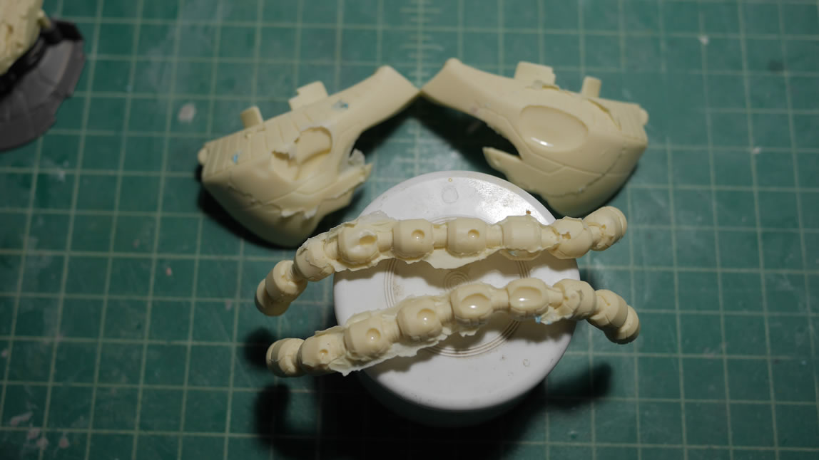
I actually started cutting and working on modifying the existing cables for the head and realised that after I started on one, I’ll need to do the rest of them. So the smarter thing would be to mold and cast a master and have an endless supply of them. Since this would take a few days to get that done; I went with option C. Take the existing cable, measure everything and design it in blender. The bonus is that I don’t have to sand down the stupid mold lines in the original cables – I do have to sand down the support material contact points – but that’s much easier than the solid mold line. The cable pieces are also solid pieces so there is a need to drill them out as well to thread them over the new base cable. Yeah, no way in hell, I’m way too lazy for that.
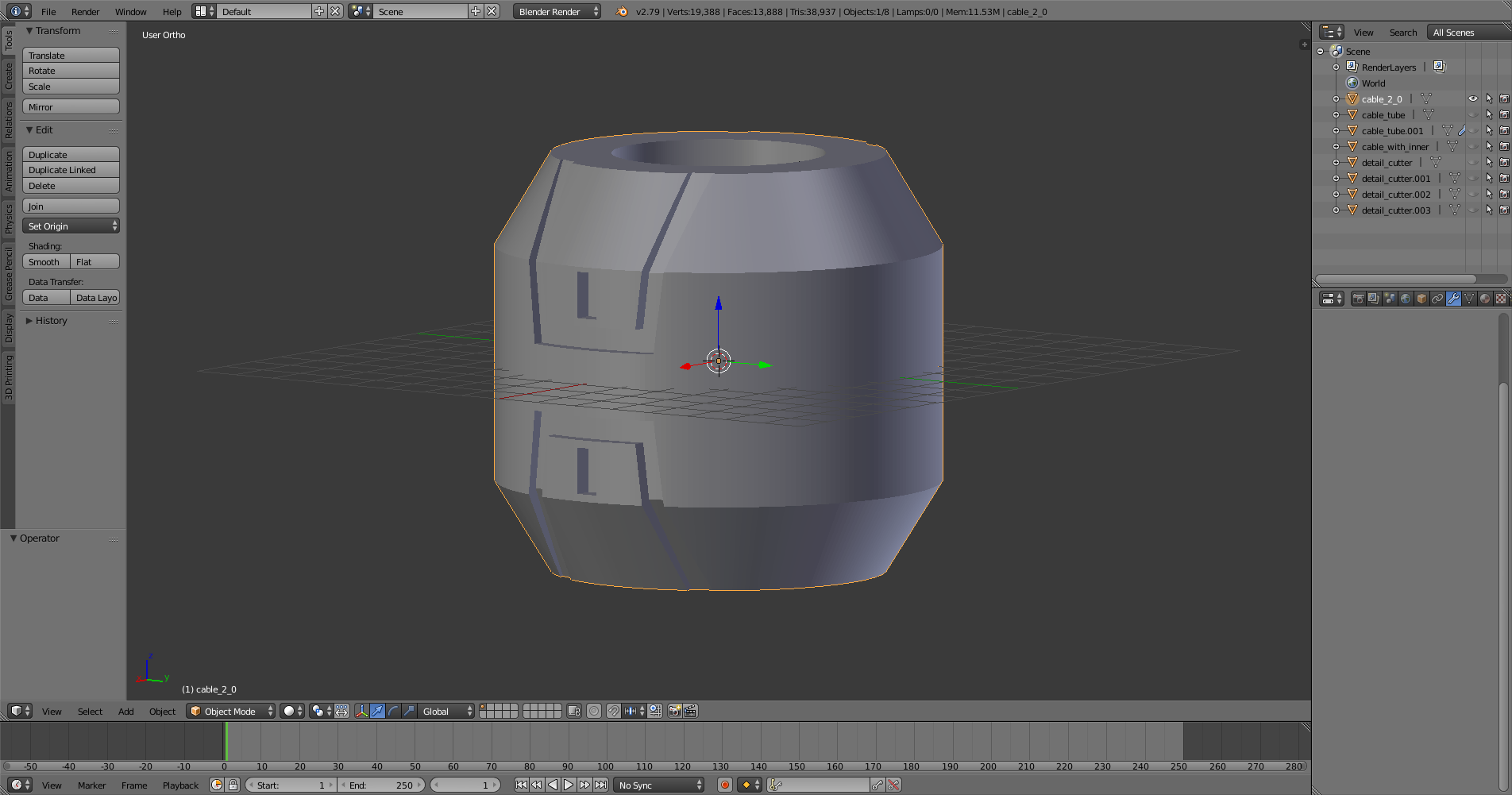
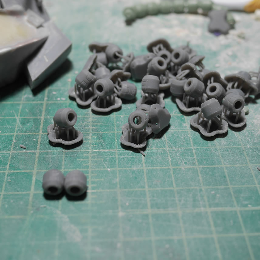
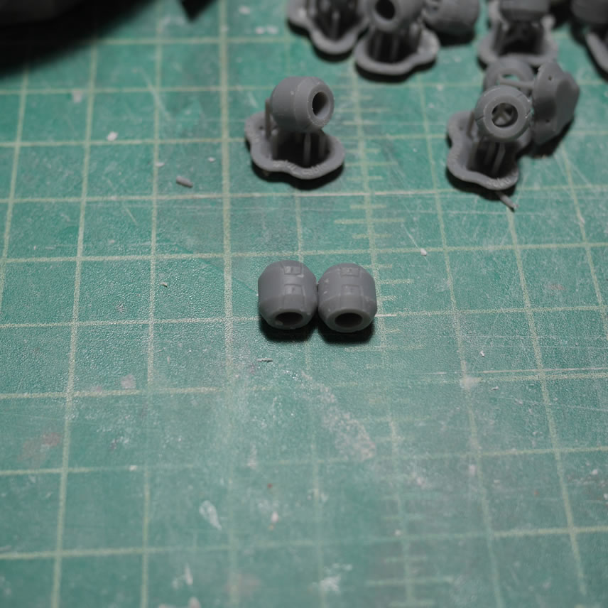
The design time took an hour, print time was 4 hours to print 24 copies, and another 45 minutes to an hour for the post processing stopes and they were ready. Speed AND accuracy!
September 3, 2019: Slow progress, but I hit a decent milestone at the end of this past weekend with the first session of primer, so it’s time for a post. I have a couple of tool discussions here so this will be good for future reference as well. First up is the drafting compass. We’ve all used these in the past to draw circles on paper. There is precision with the wheel adjustment so here, I can use this to mark up an area on the kit for drilling a hole. The back of the head needs a attachment point for the Gouf’s cables. The compass comes in handy to accurately measure how how far from a point of reference to make the marks. And I can easily mirror the mark on the other side of the head so I have symmetry.
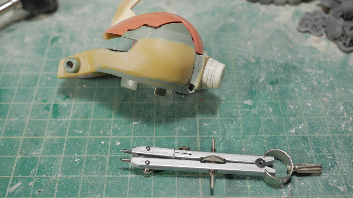
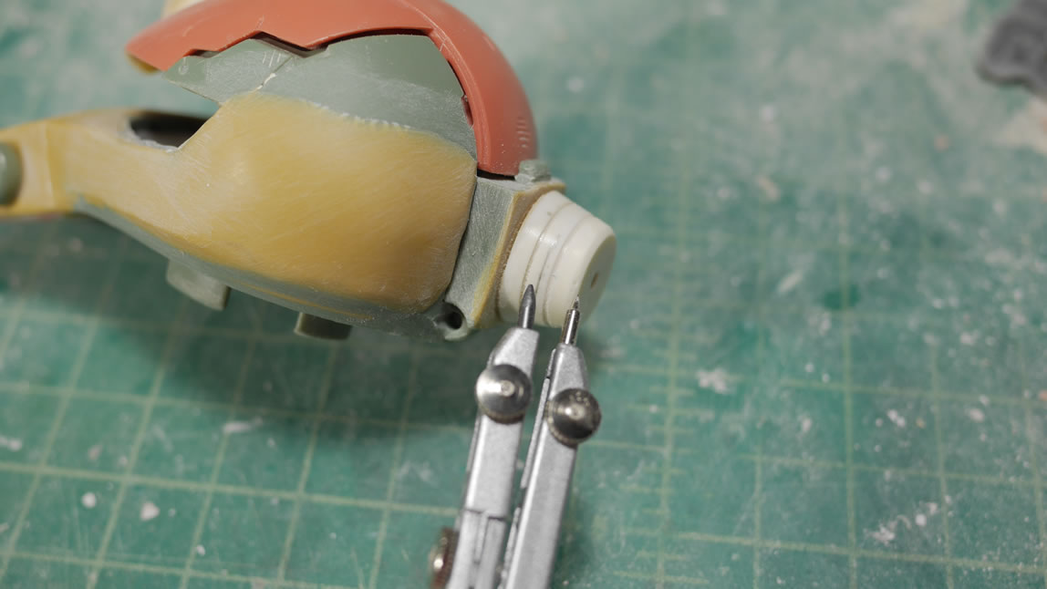
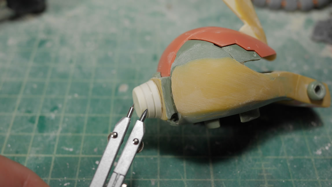
Once marked off, I have a guide for drilling in the holes that will eventually dock the head cables.
If I take the compass and use the needle end as a guide along the bottom of a plastic piece, I can run this line and effectively draw a parallel line to the edges of the parts to draw in a guide that I can then tape along and scribe in a parallel detail line.


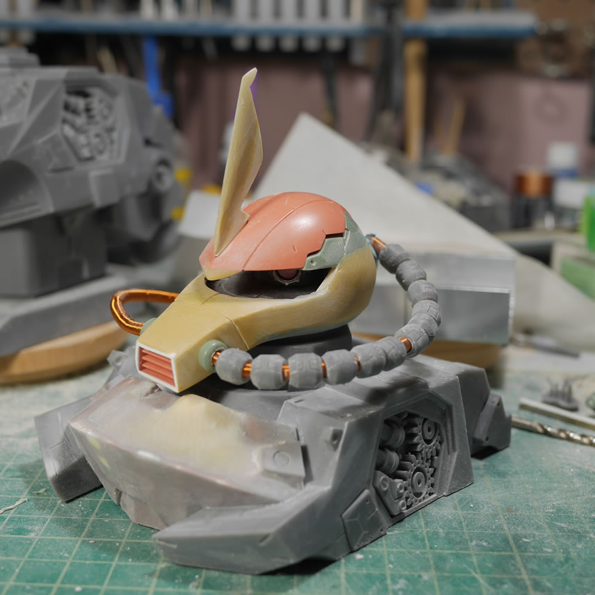
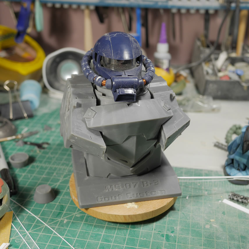
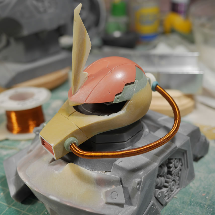
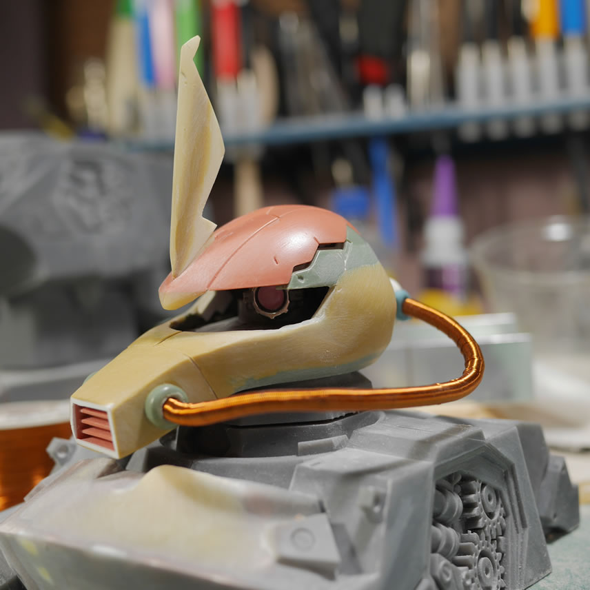
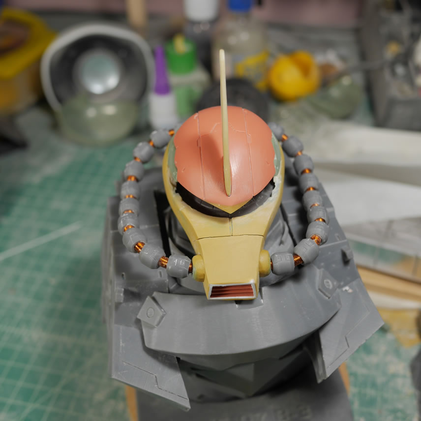
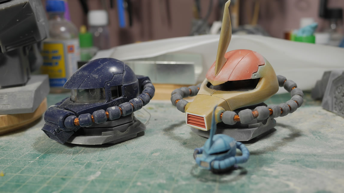
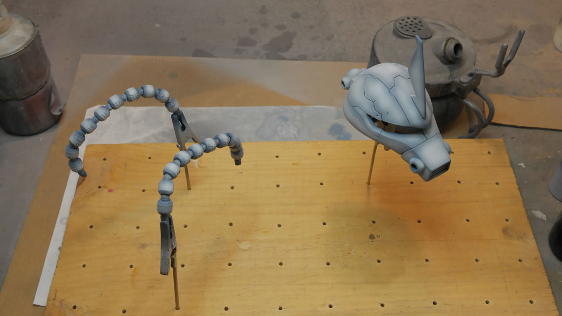
From the last post, I was testing the cable tube fitting. I threaded the other tube and I have a quick test fit for the tube. Things are starting to look less Zaku I-ish and and more Goufy. I also start doing some bends in the cable wire to get the correct shapes. I originally thought that I could just mold the individual collars and then the cable separately, but decided that I wanted to glue them into position. I cut the original cable front connection point, drilled through it, and glued it to the front of the nose where I had drilled in some holes as the docking point for the cables on the front of the head.
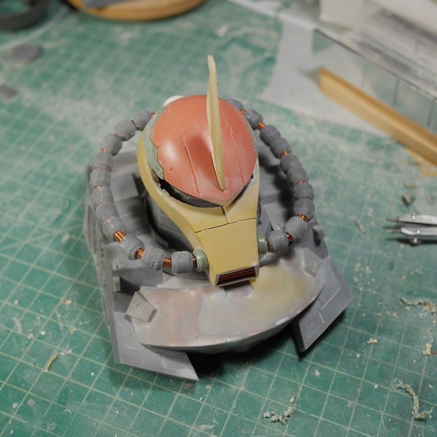
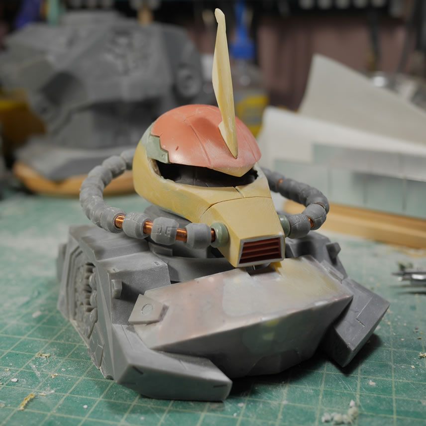
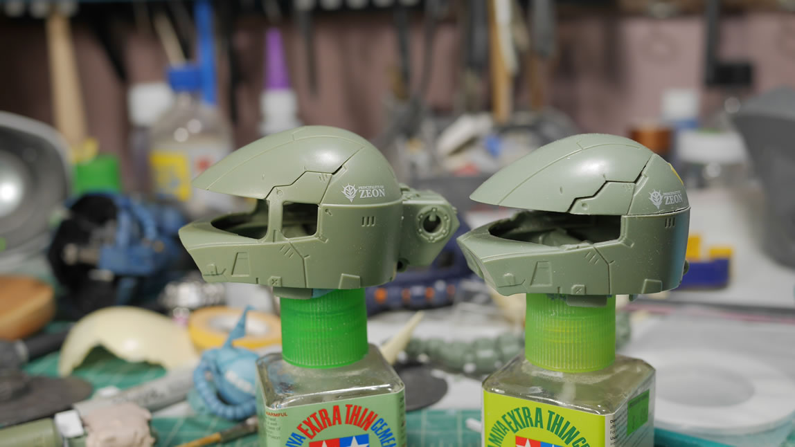
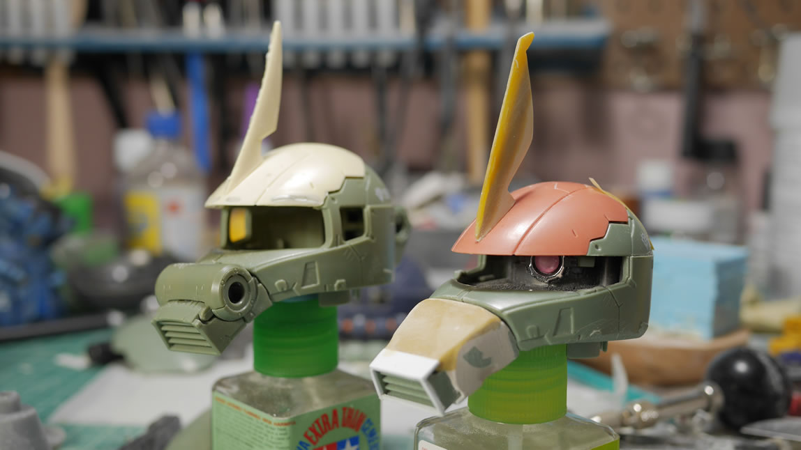
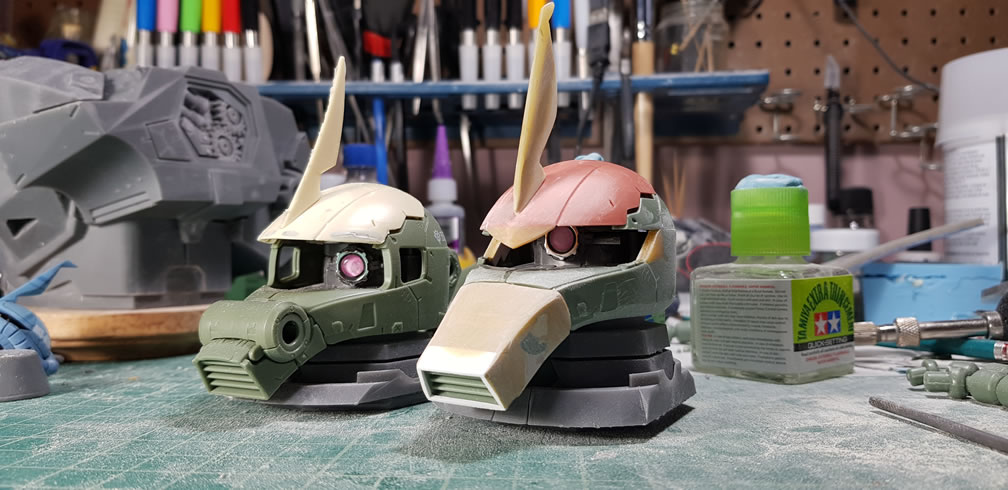
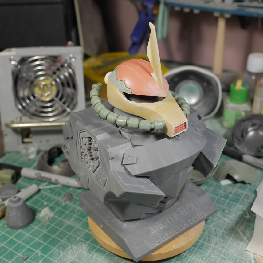
Here is a quick comparison of the Gouf against the almost OOB Zaku head.
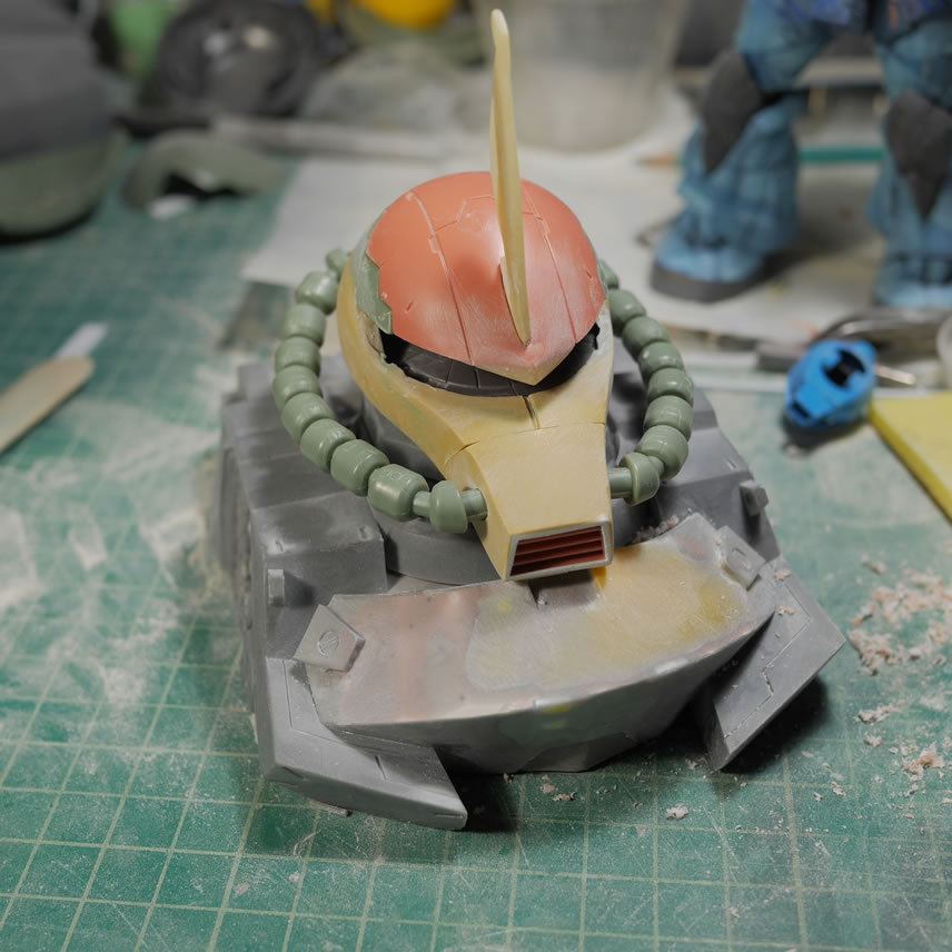
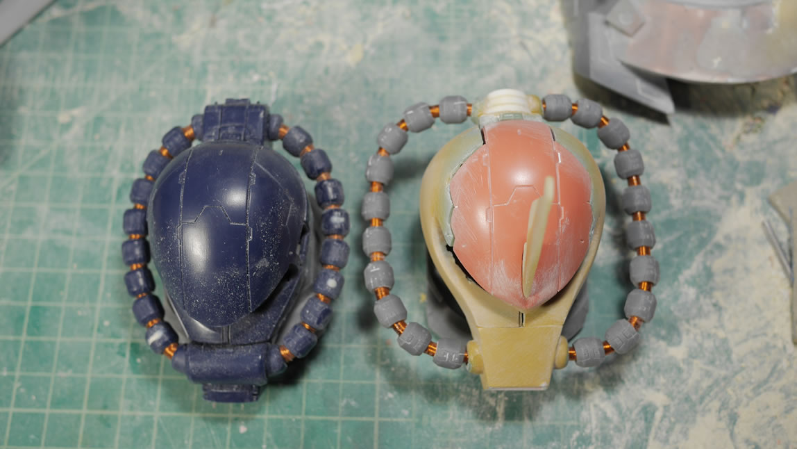
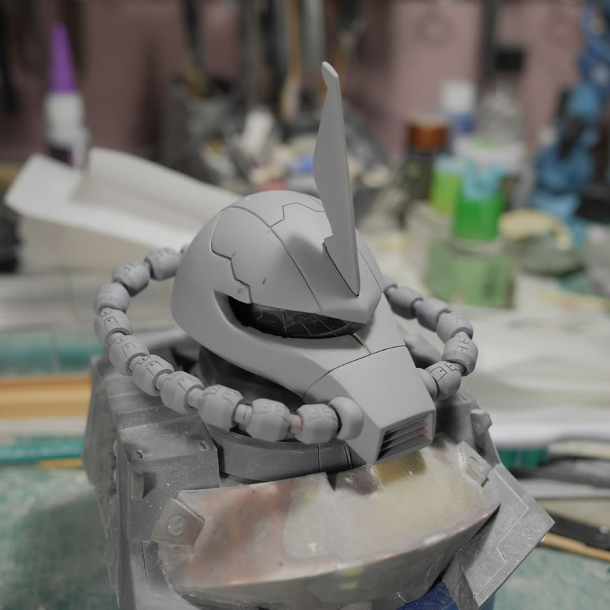
The first picture shows the glued cables. The nose cable attachment point got some putty to fill in gaps and solidify that connection. CA glue is a bit brittle so too much twisting snaps this piece off the nose. Putty helps cement the add on piece. The cables flare out from the head a bit by design. I based the design off the Gouf Custom head from the Neo Grade resin conversion kit I built several years ago. But they looked to be flared out a little too much, especially if compared to the Zaku where it looks fairly tight against the sides of the head. Putty is applied to the sides of the head to flare out the cheeks and sides of the head. The cable collars are glued to the frame cable so that can be twisted and shaped into a final form.
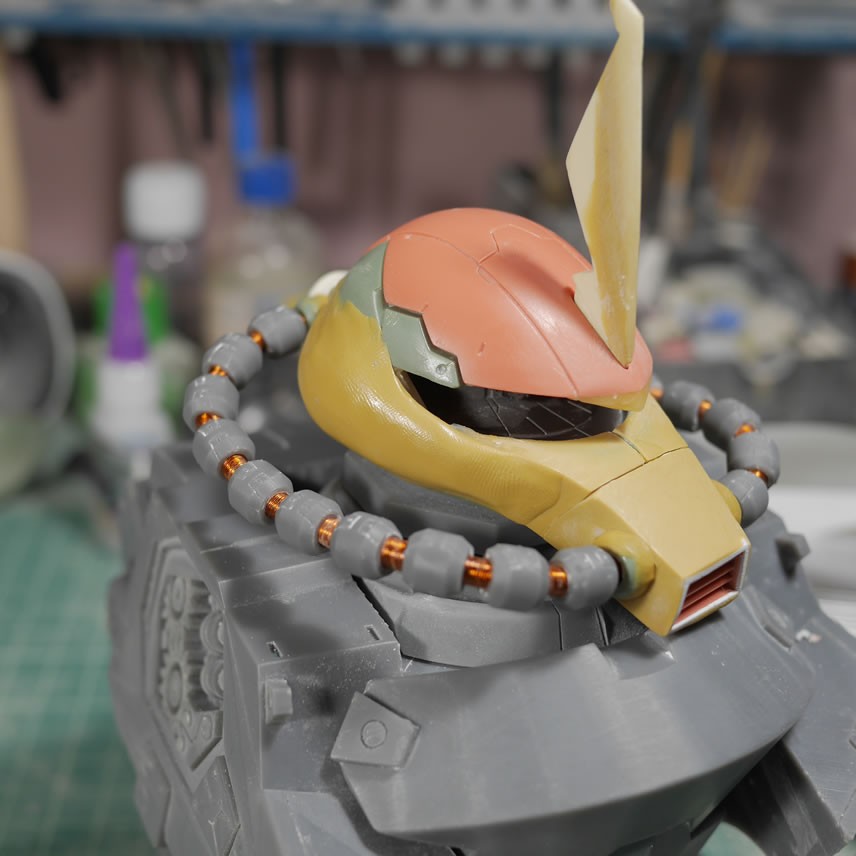
The sides of the head are sanded down to get the final shape. Light curing putty is applied to smooth out transition areas and do more build up from the lower sides of the head upward. It is all sanding sticks and sanding sponges from here on out.
In the middle of sanding and cleaning up things, I snapped a picture of the Zaku head as a comparison to how different the sides of the heads as well as the nose looks now. The cropped off top of the head is noticeable too.
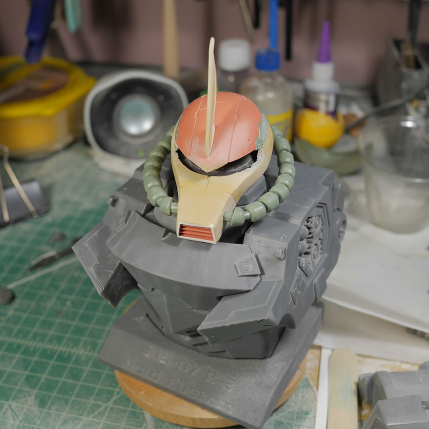
Cables are now ready. I glued the end pieces of the original Zaku cable to the back of the head at the holes from the beginning of this post. Putty is applied here to help cement them into place. The cables fit on the front and back and we have more comparison test shots. The original part I used for reference is in the middle picture. The last picture of the set is the bottom side of the nose to see that I only extended it by very little, but it makes a huge difference.
Lots and lots of sanding to smooth things out before the first primer session. I’m not going to worry about catching everything, but I’m trying to catch as much as possible. Things still look pretty mismatched with all the different putties, different kit colors, etc. But still sanding and doing a few details.
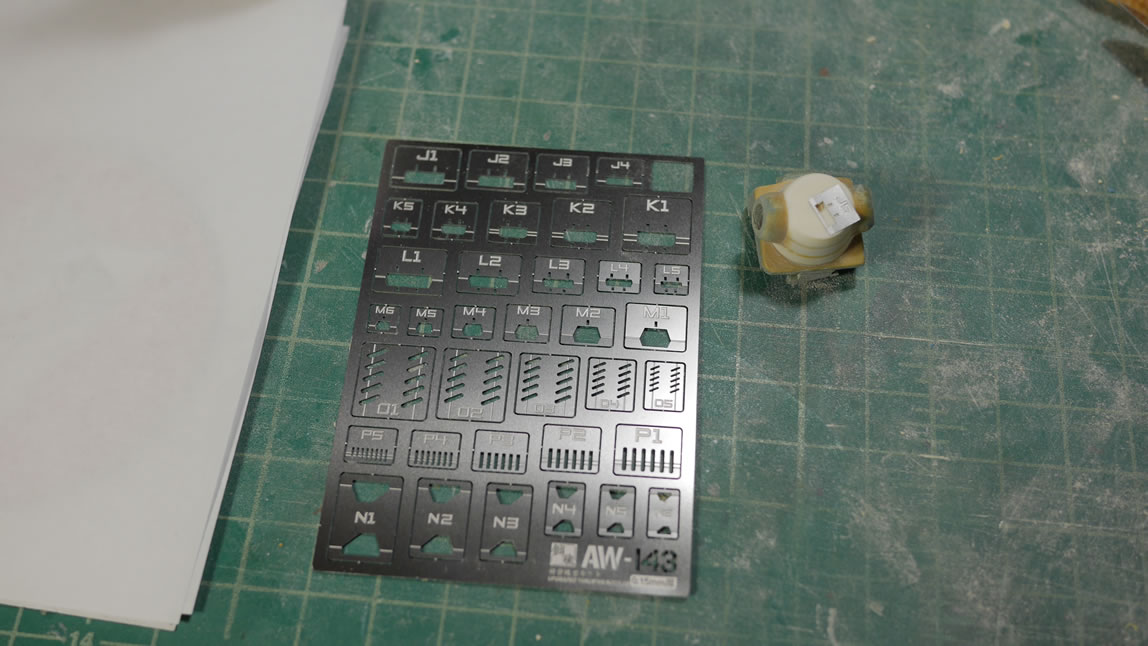
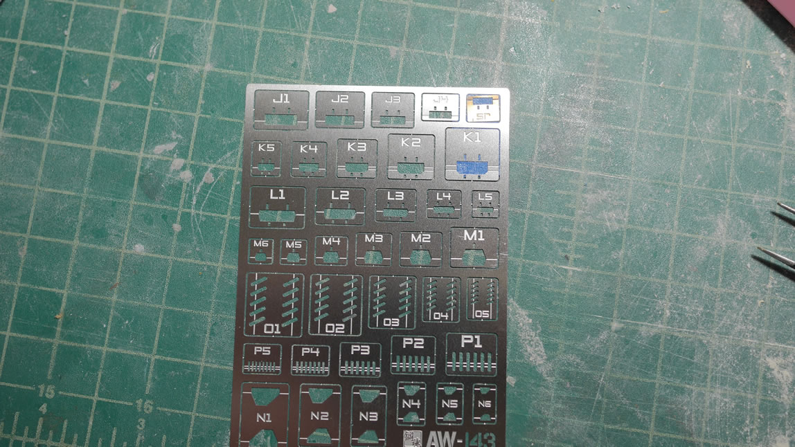
Next up is something not new, the scribing templates. I’ve had and been using Hasegawa scribing templates for at least 15 years now. What is new, is how some newer companies are approaching the scribing template. It’s still a sheet of templates, but each template detail is detachable from the template tree. This makes working with the templates on smaller pieces much easier than trying to position a 4 inch long template sheet.
- Step 1: Remove the template from the tree and position it on the part you want to scribe
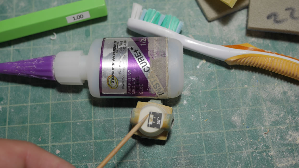
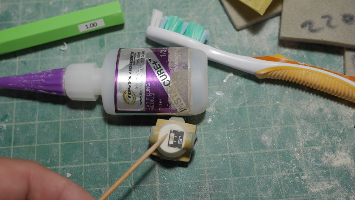
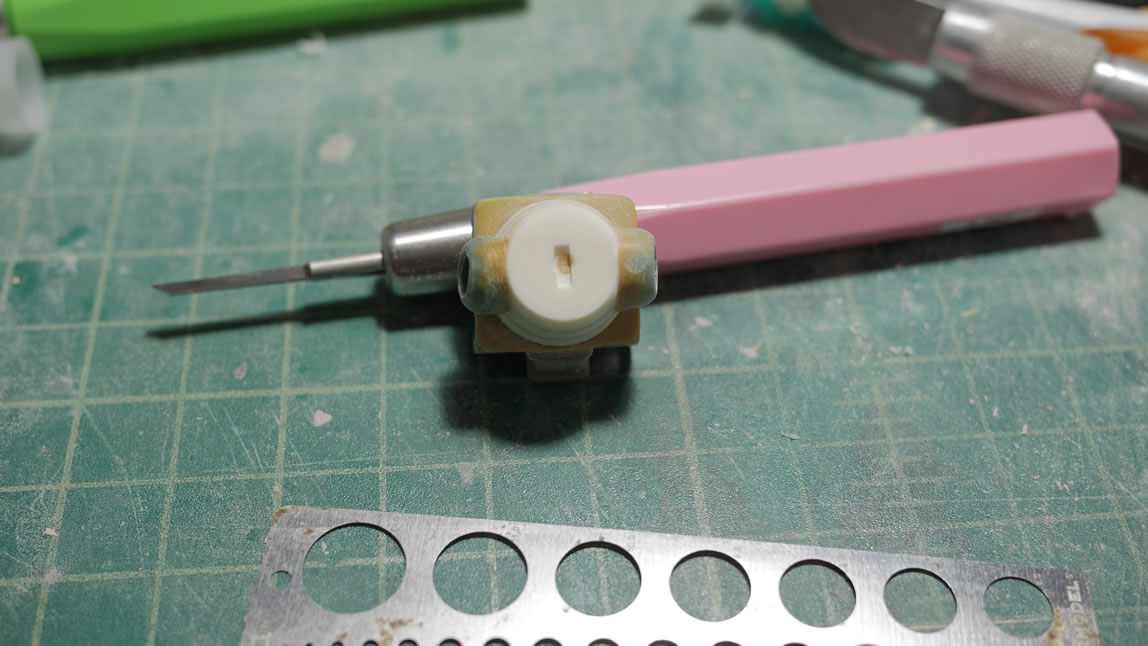
- Step 2: Attach the template to the surface of the part. In the past I’ve used tape, but I have found that this solution isn’t the best. The template will move if too much pressure is applied while scribing. What I’ve learned recently, is that folks have been using CA glue to attach the template to the part. This is great as CA glue dries and bonds very quickly, yet the actual bond is quite brittle so that the template is easily removed from the part. Here I use a toothpick and apply CA glue to 4 corners on the edge of the template.
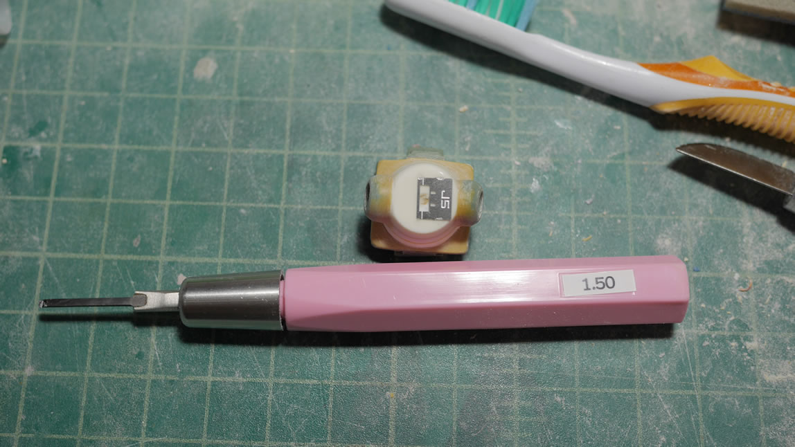
- Step 3: Scribe using the template as a guide and whatever scribing tool you like. Here I’m scribing in a 1.5mm recctable detail.
- Step 4: Pull the template from the part. I used a wide hobby knife blade and just twisted and the template popped off.
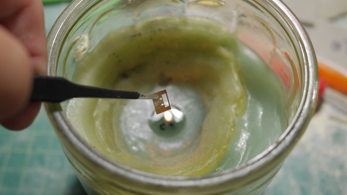
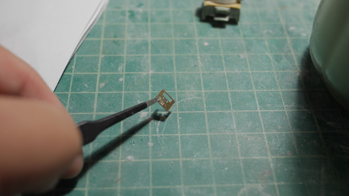
- Step 5: Clean off the excess CA glue from the template. Fire works well here. I lit a candle and using some tweezer, held the template and burned off the excess CA glue. Do this in a well ventilated area. The CA glue is only on the edges of the template so this was easy to do.
- Step 6: Place the template back with the tree and attach with some masking tape so that I don’t lose the template. The the template is slipped back into the packaging plastic it came in.
- Step 7: Clean off the excess CA glue off the part with a sanding stick.
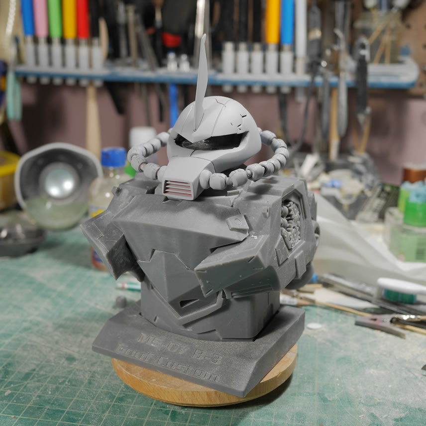
Details sanded, and the parts are prepared, time to spray some primer. A quick assembly after letting the primed part sit in the dehydrator for a few hours at 122 degrees. Its starting to come together.
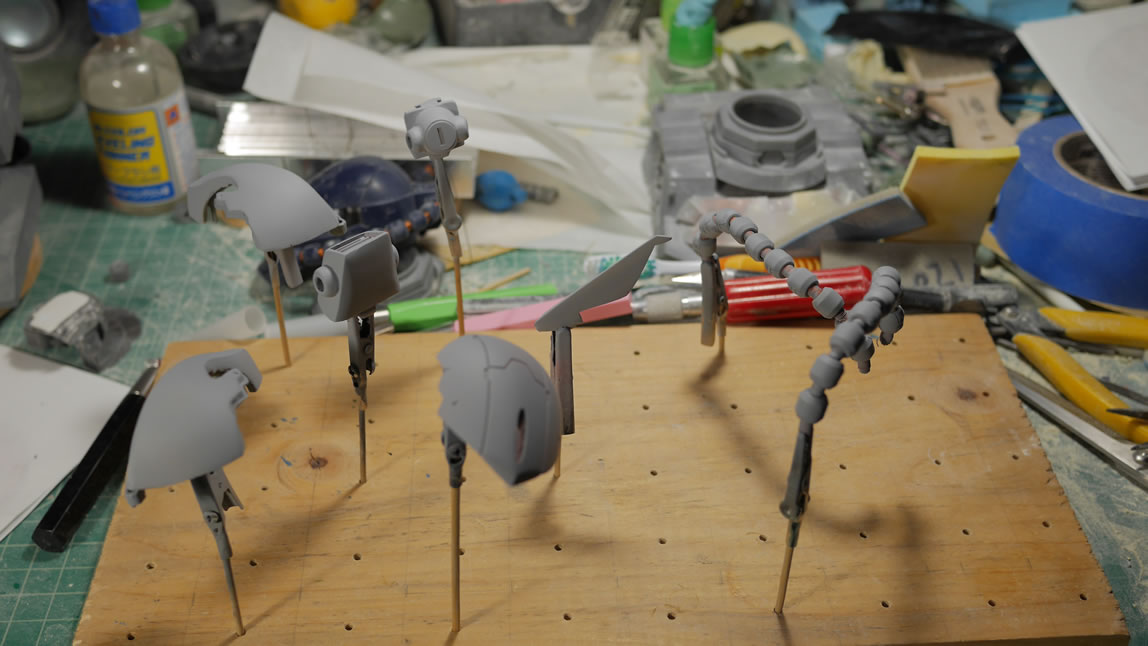
First a test fit on the half bust piece.
And some turnarounds for the display on the full bust piece. There are areas that need attention and I will need to scribe in more details into the head that were erased when I cosmetically puttied up the sides of the head. But things are pretty good.
September 30, 2019: Time for a little update on the Gouf Custom Exceed Head conversion kit progress. This has been a fairly productive month, most of the time has been spent making the mold and making casts for all the parts. But time to play some catch up. The last time I left off, I was still working getting the shape of the head correct, or to a point that I found acceptable. After the priming sessions to check for the correctness of the surface, I can get to scribing the final bits of detail for the side of the head. There is a definite order of operations here, since scribing before getting the shape right would just lead to rescribing details that are covered up by more putty used to shape the head. The first thing is to lay down some tamiya masking tape for curves. The tape is a little rubbery and considerably thicker than the standard yellow tamiya masking tape. This allows for the tape to curve and keep a continuous line along the surface. This is perfect for masking curved surfaces and just having curves. I’m not using this to mask, but as scribing tape to help guide some chisels. If I am careful with the chisels, I can scribe in a perfect line. For the purpose of scale, I used a .5mm to scribe in the lines. I started with a .3mm but found they were a little too thin for the scale. 3mm Mad Works carving tape is used as the scribing guides for the detail lines perpendicular to the line that runs along the lower half of the head. I liked using the Mad Works carving tape over dymo tape since it’s clear, which makes alignment very easy; and I can reuse the tape a couple of times in comparison to dymo which is only useful once then the stickiness is completely useless.
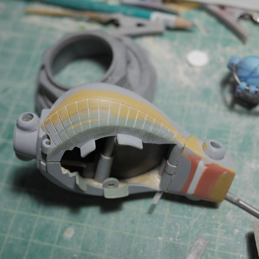
Here is a before and after shot of the lower half of the head details. I also scribed in some detail lines near the visor opening using the same Neograde kit I used as the reference for building the the conversion. Once those were scribed, I did a quick prime session and did a few final checks before setting up the parts of molding.
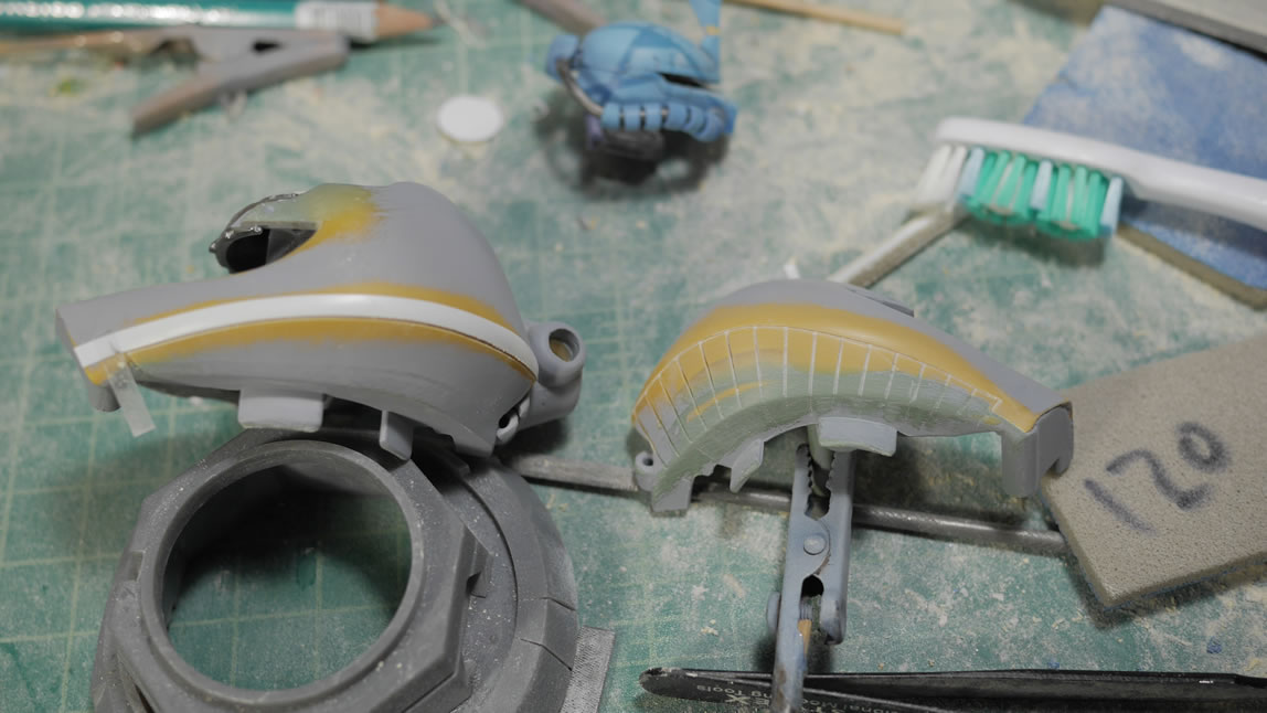
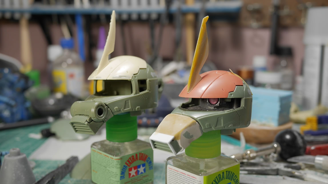
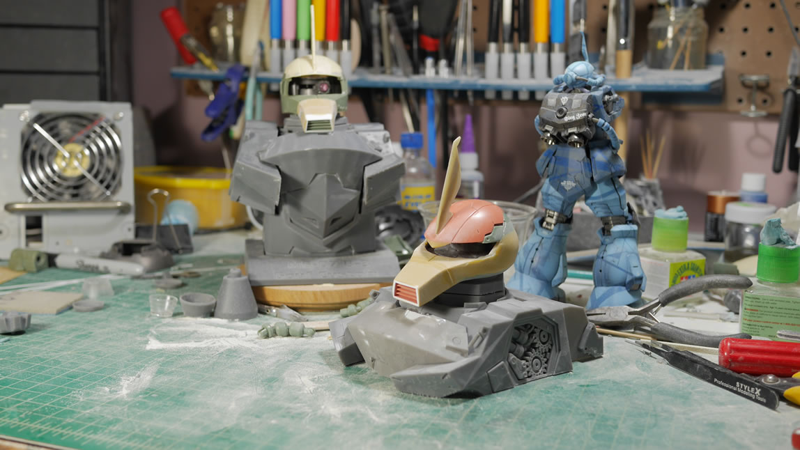
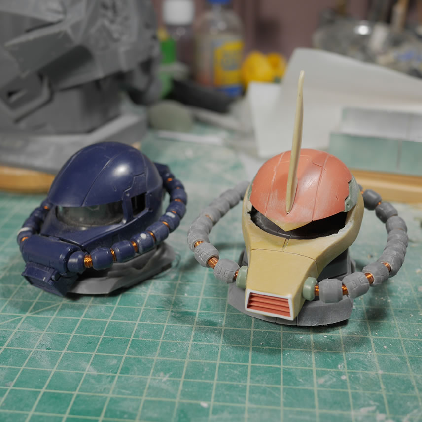
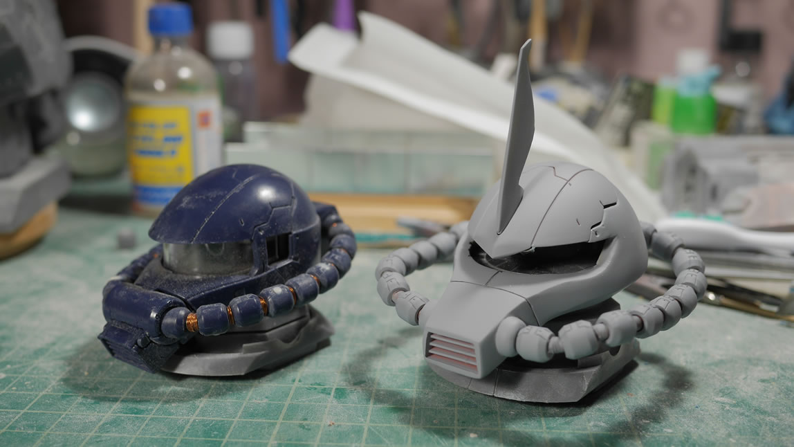
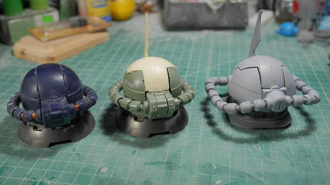
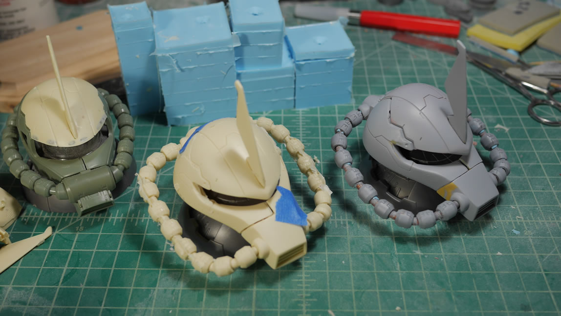
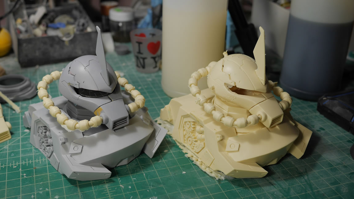
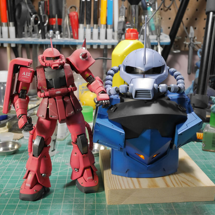
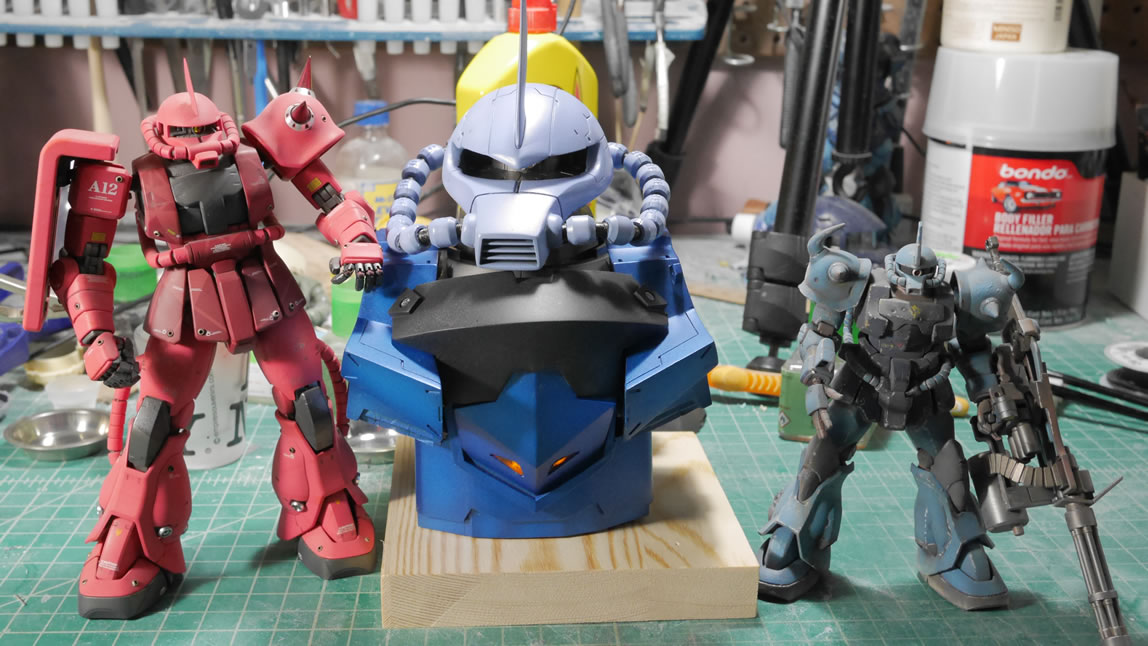
Satisfied with the priming session, I put the kit together and here are some comparison shots with the two other Zaku Exceed heads. Hopefully the differences are pretty clear.
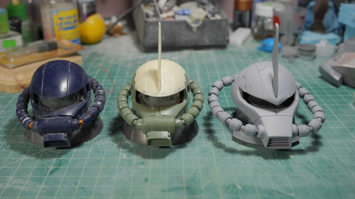
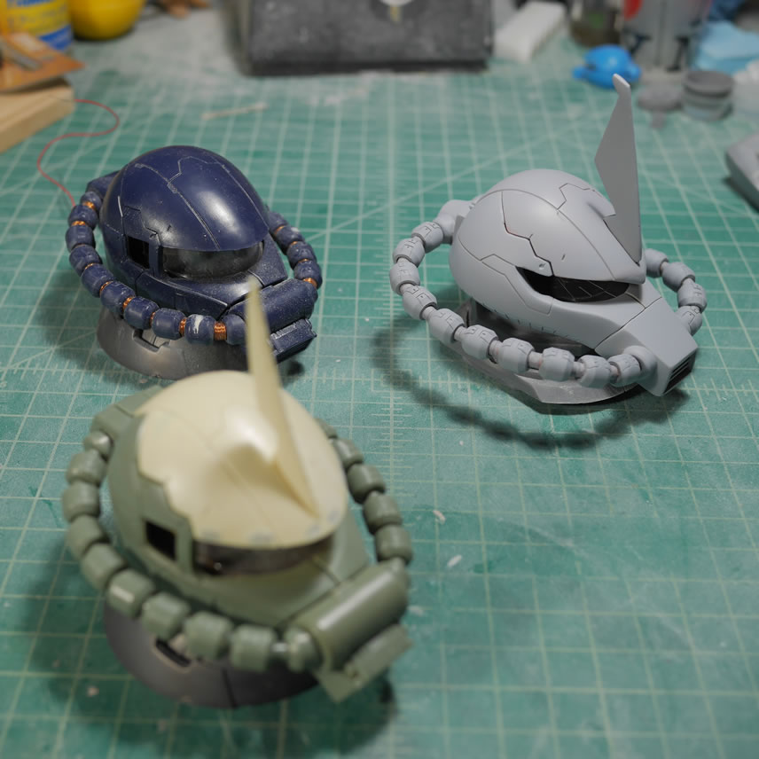
Showing off the lower half of the head and you can see the curve in the head cable that is special to the Gouf and the differences in shape and details.
A quick pictorial check on the two busts that I have. The half bust will be the version that gets molded and cast. It would just be too cost prohibitive and time consuming to cast the larger bust. My original plan was to cast that large bust but once I had the sucker in hand, I realized the scope of that project was beyond my willingness to commit. So the second picture is what will be available very soon! I could send it out to some place in China to have it molded and casted, but then the next day I’d see the kit on sale at E2046 and other pirate resin sellers. So yeah, not a fan of that idea.
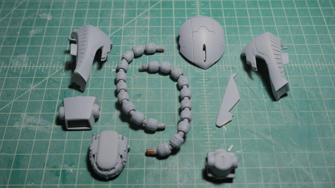
The kit is taken apart and it is pretty much just like the Zaku Exceed head in total parts count. The one difference is that I did not account for the visor. The original visor can still be used, but will need to be trimmed/sanded down to match the correct height of the Gouf’s visor opening.
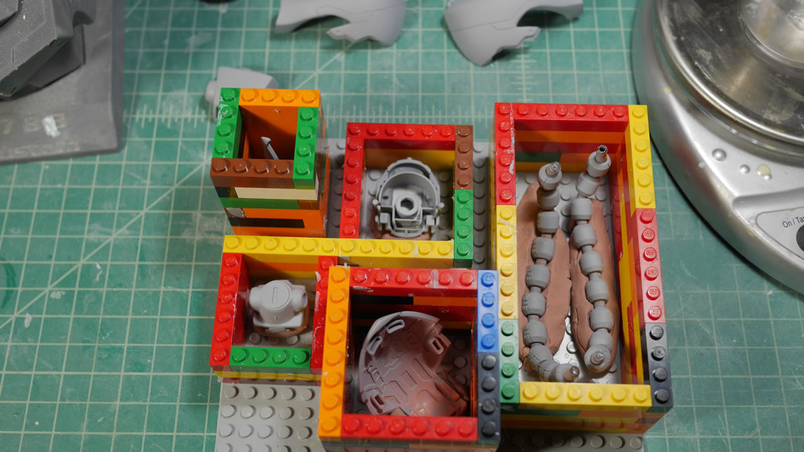
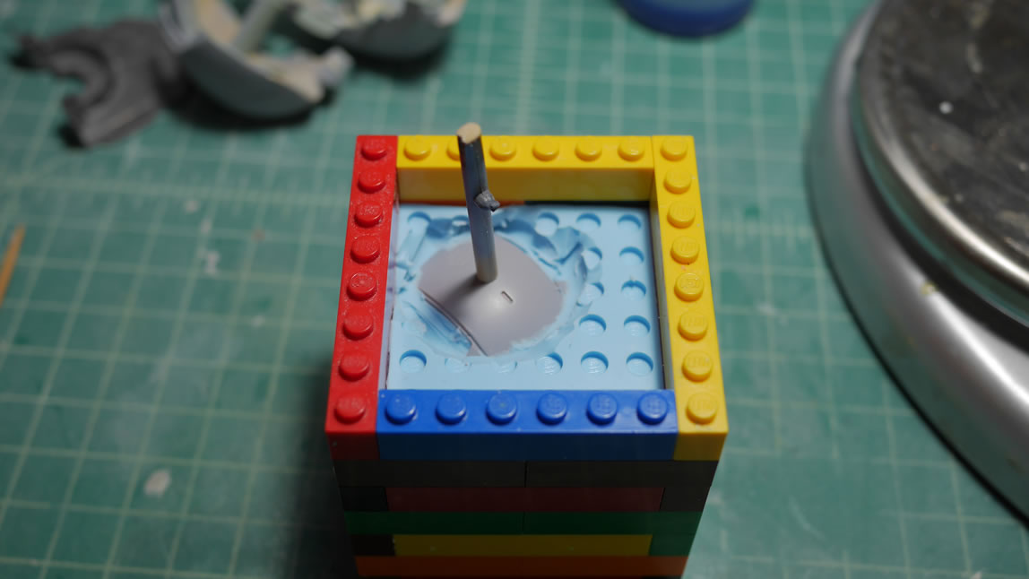
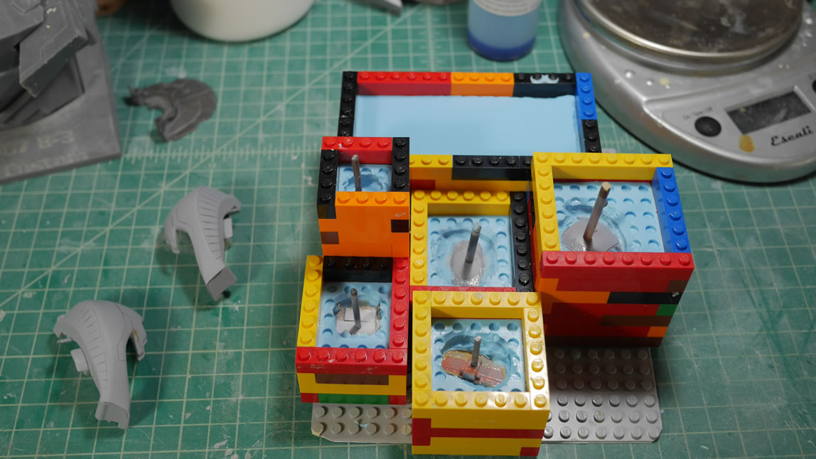
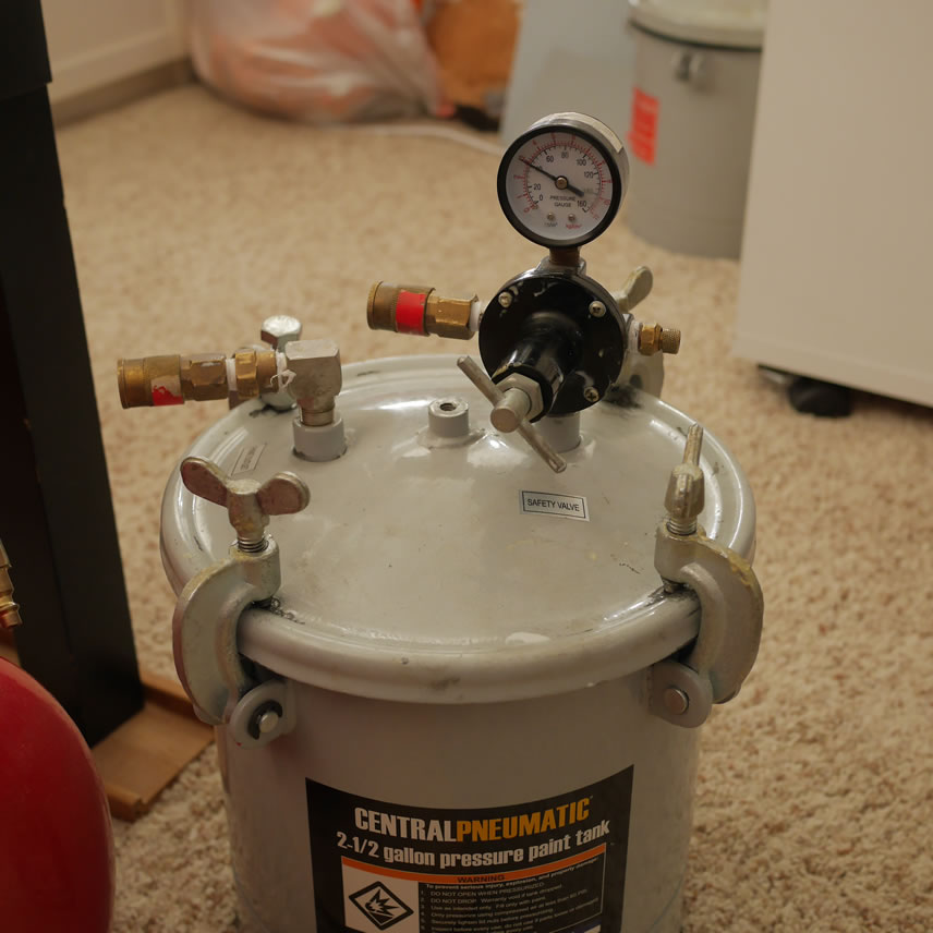
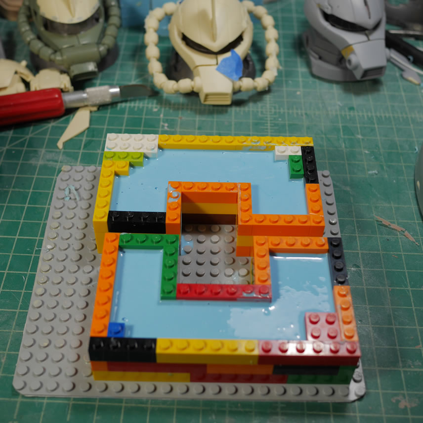
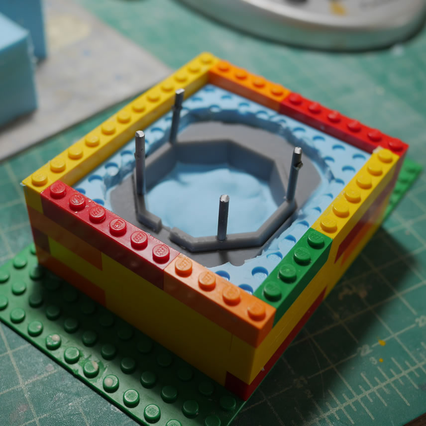
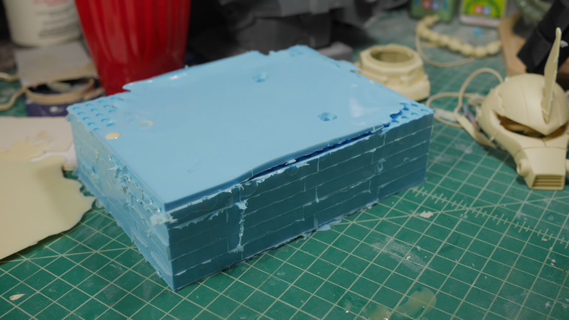
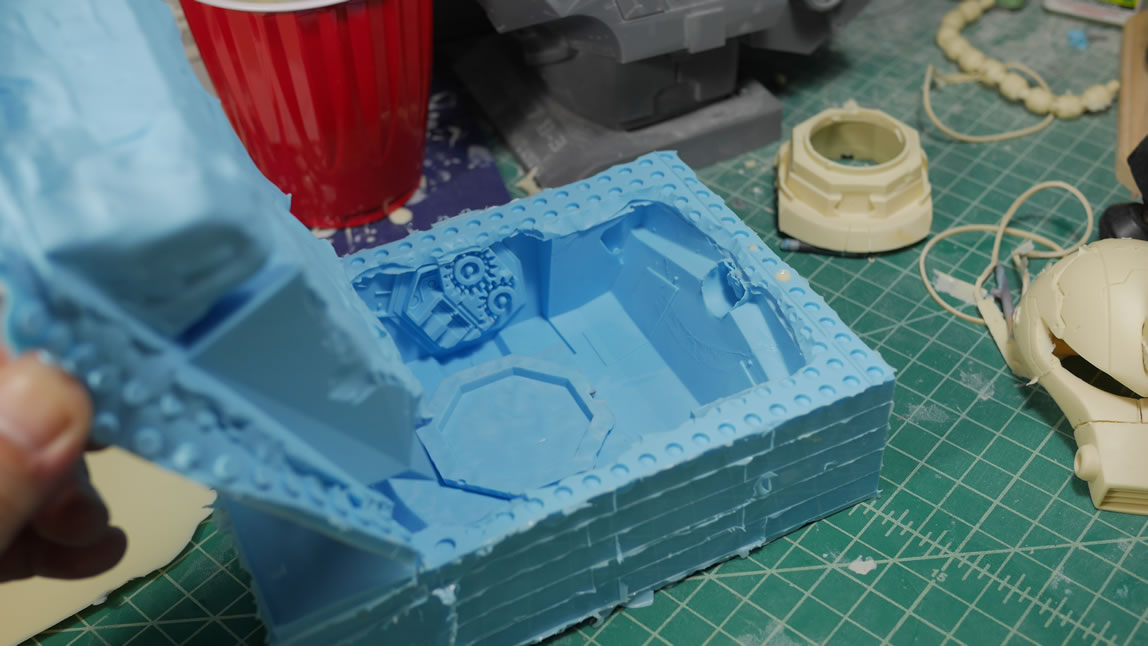
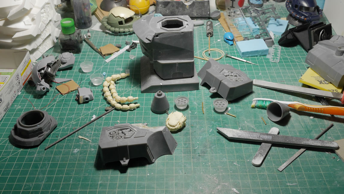
Silicone molding I like using legos as my mold boxes as it is very modular, but it can be a waste of silicone. I’m used to this method for making molds so it’s always best to work with what’s most comfortable. Holding the parts in place and in some cases filling some cavities in the parts; I use playdough. It is easily washed off and can be reused so for my purposes, it is the perfect clay for silicone molding. Once that is done, the mold is filled with silicone and the placed in a pressure pot for curing. Once cured, I break the molds out of the lego pieces and have one half of the eventual mold. I flip the mold and rebuild the lego box. I glue on a piece of plastic sprue to a flat surface on the parts and let that cure up. Vaseline is applied to the part and one side of the mold to keep the silicone from sticking to itself. And the second half of my squeeze mold is poured. The plastic sprue will act as an exhaust port for the resin when I get to pouring. This will be very important further down this post. The parts are placed into the pressure pot which fills the pot with air and compresses any bubbles that may form.
I also did a live broadcast of this process while working on another mold part, so that video can be seen here:
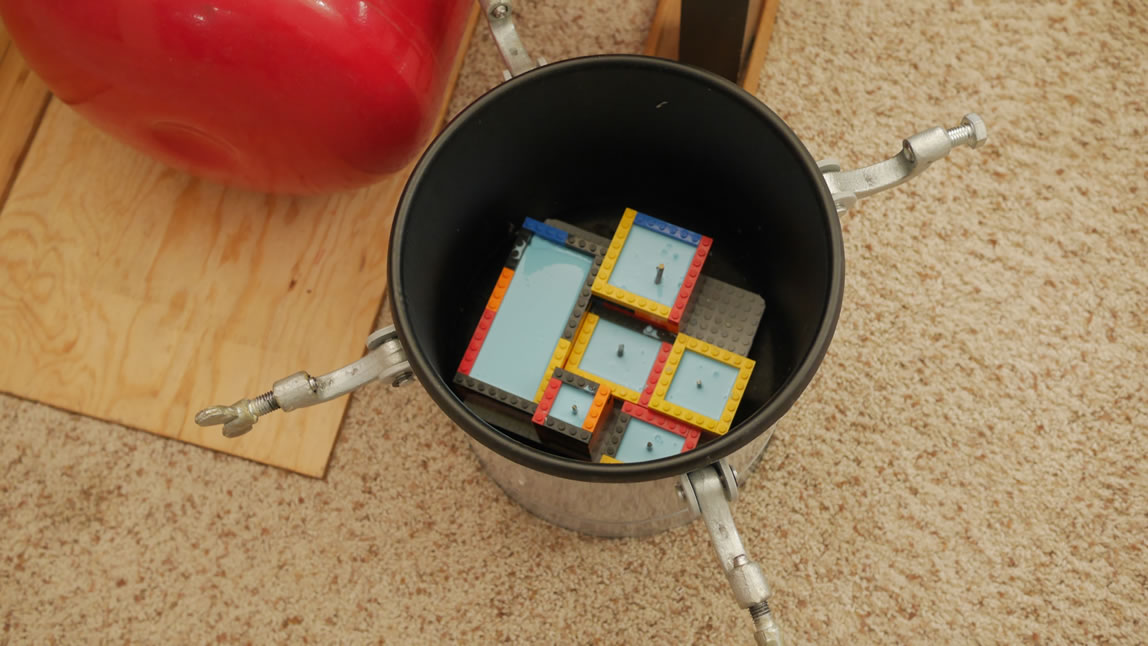
And in the pressure pot, the can is filled to 40 PSI and the molds are left to cure for about 3-6 hours.
Once cured, the masters are removed from the molds and mold release is sprayed into the molds. The molds are then placed into an oven at about 140 F to bake the mold release into the molds as well as activate the release properties. Once that is done, it is time to mix some urethane resin and make some casts. Below is the first cast and pull which is pretty good so far. After a few mold pulls, the molds will be reconditioned with another spray of mold release and baking cycle to help prolong the life of the molds.
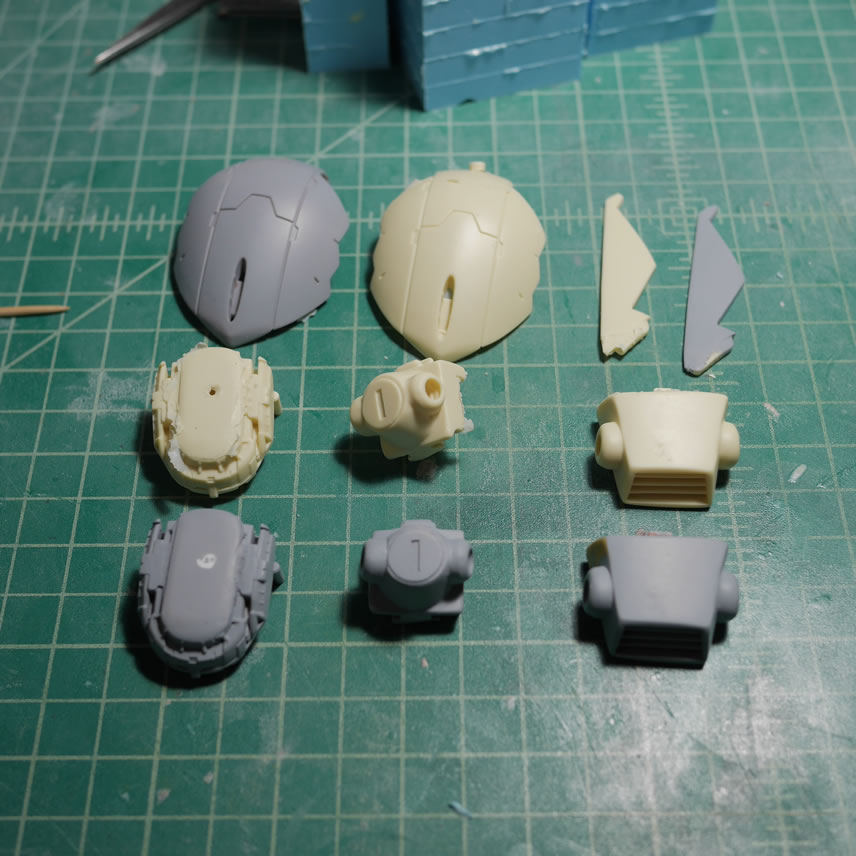
Earlier when I stated that we need vent holes; that statement is demonstrated clearly here. If I’m not making mistakes, I’m not model building. For the head sides, I forgot to glue in a piece of spruce for the vent holes, so the cast without the vent holes shows what will most likely happen. I got a huge bubble. Without a vent hole, while under pressure, the bubbles in the resin has nowhere to go but to the top of the mold, and gets trapped creating a huge bubble in the cast. I can fix this by cutting out a vent hole in the silicone mold. I had a similar problem with the cables. But the problem with the cables was deeper, I tried to save time by molding both cables in the same mold, and that was just mistake 1 of many. Short cuts always come and bite me in the asshole later. But this will be addressed later, I’m way too excited on getting the first casted copy out to worry about my casting problems.
The first cast sitting next to the master. Not too bad, but for mass production, I will need to make some adjustments and fixes to the molds – for other pieces, a whole new mold is warranted.
I also went live with a video on casting here:
Time to remake the molds for the cables. I split them to their own molds this time; something I should have done the first time around. The same process is being done here as above. I also started on making the mold for the neck piece, this time not forgetting to add in the vent holes.
Taking a break from the casting cycle, I went and finished up the fixes to the bust to prepare it for molding. After a couple of sessions with the light curing putty, the sanding sticks, and a few primer sessions; I got the surface good enough for molding. This is where the above silicone molding video above covered, at least partially.
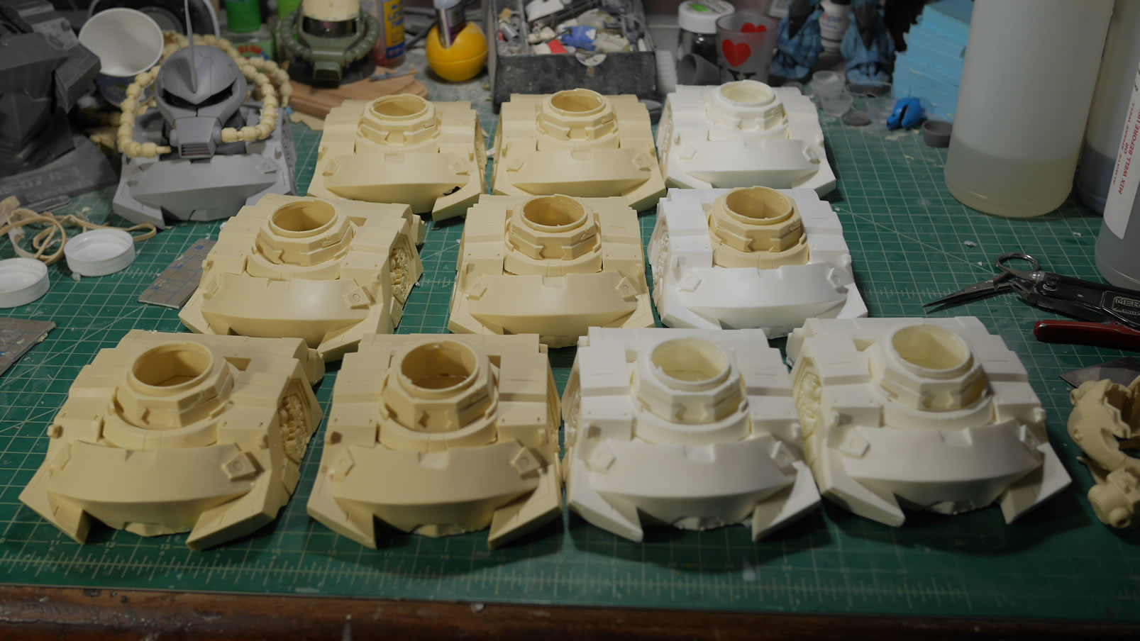
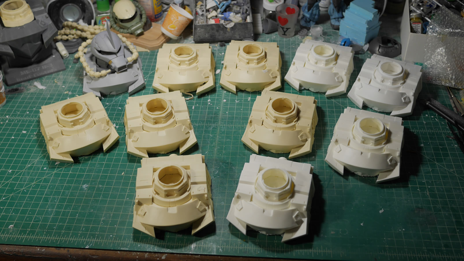
Now I have all the molds I need for the project and here’s the first pull on the bust; and it’s a near perfect copy of the master. Time to build my army!
The mold for the base is massive, but so is the base. This makes it all the more clearer why I went with the half base instead of the full bust I had created first. I plan on casting a total of 10 busts to put out for sale.
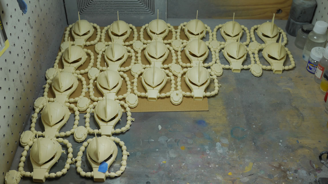
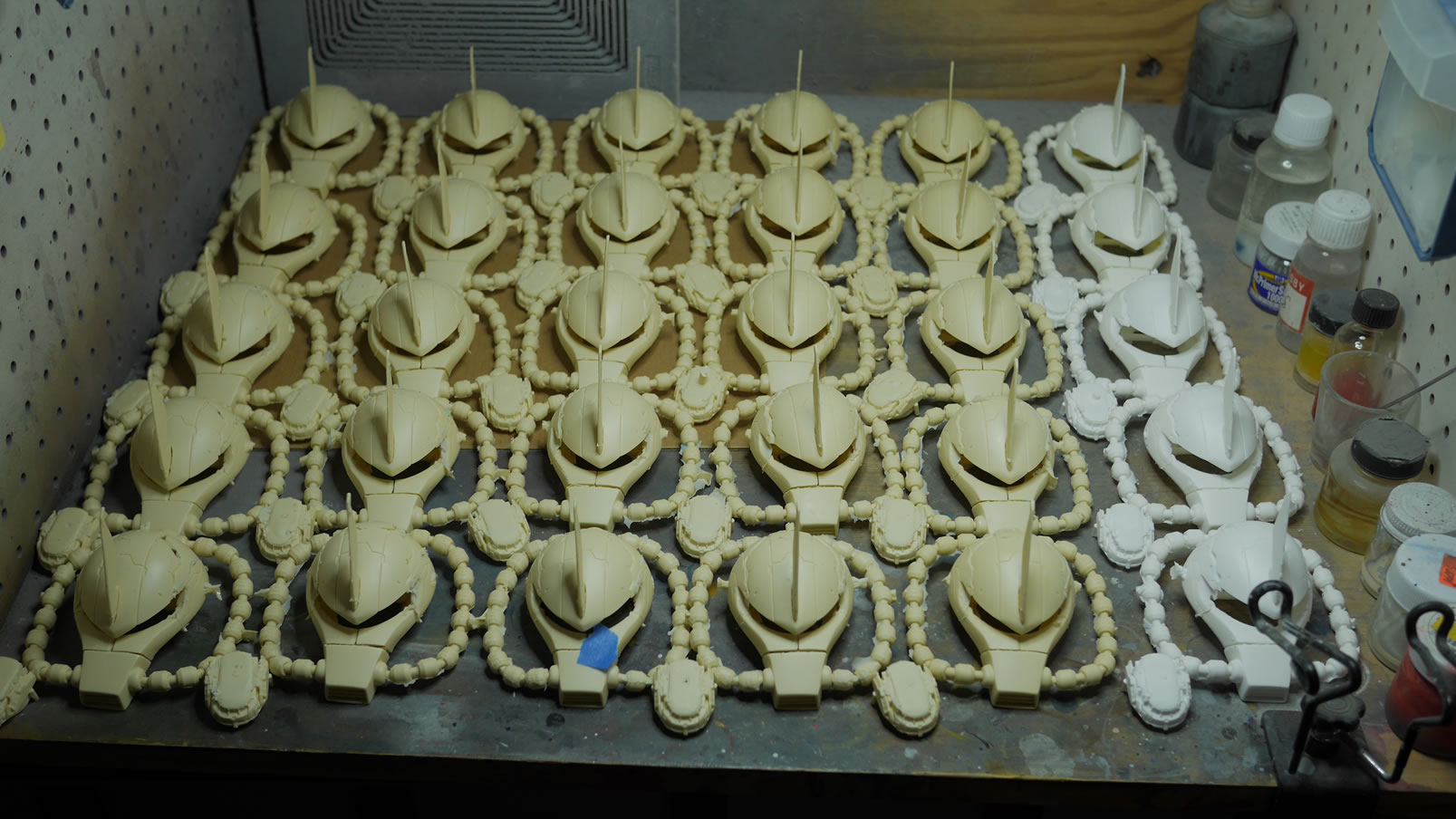
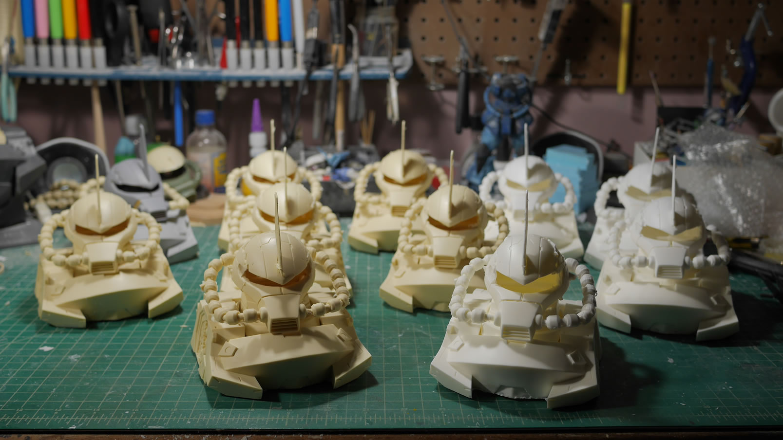
As of last night, I have an army of 20 Gouf heads. My magic number I want to reach is 30, then I can start shipping the heads out.
So you want to buy one of these heads and or the bust? I have the kit up for pre-order in the store: Those Gundam Guys Online Shop Pick up a shirt or two as well to help support SCGMC! The heads/busts will ship once I hit those magic numbers of 30 and 10 casts respectively. This should be another few weeks, so about mid October to end of October. And of course, if the preorders do well, I will try to make more casts dependant on how well the molds hold up after I’m done with the initial casting run.
I hit the goal of 30 Gouf Heads and 10 busts casts. They’re up on the site for sale and a good number of the busts kits have been sold and shipped. Since SCGMC is coming up, I’ll have anything left over for sale at the show. They look like little Goufy tanks don’t they?
October 14, 2019: The silicone molds starting to get pretty rough towards the end. Resin is an adhesive, so granted it doesn’t stick very will to the silicone rubber, but over time, the molds will tear and you’ll get bits and pieces of the mold tearing giving even more surface area for the resin to stick. I sprayed mold release and rebaked them a few times, but according to a friend, I should have sprayed a light mist after each pull. That could have prolonged the molds and I may have gotten a few more pulls. But the whole process is pretty labor intensive. I just wanted to be done with the goal and have them out there for folks that wanted to buy them. I’ll eventually get around to painting the full bust. Hell, I have what, 5 weeks until SCGMC? Maybe I can pull this off if I focus. I’ve been playing Gundam Battle Operation a little too much of late since they released the game to NA and just restarting a new character to play along with a newly formed tgg clan has been interesting. Its like kicking puppies. The novelty will wear off and I’ll go back to my 3 games a night – or how ever many it takes to complete the dailies.
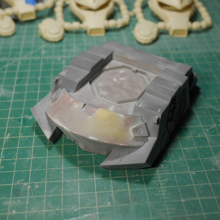
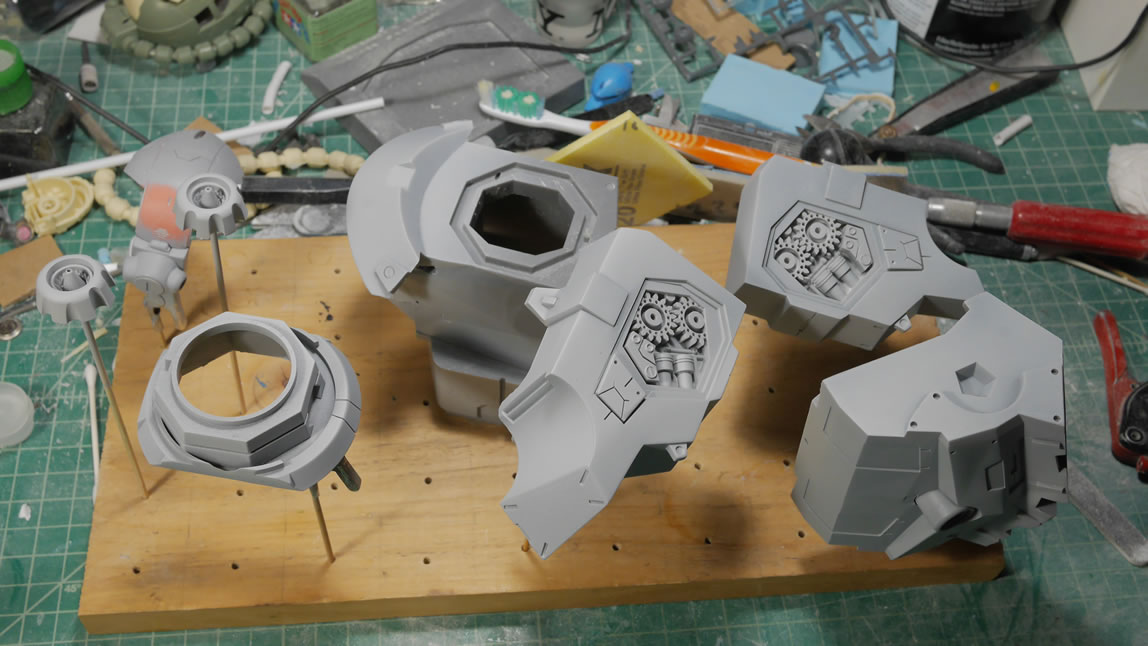
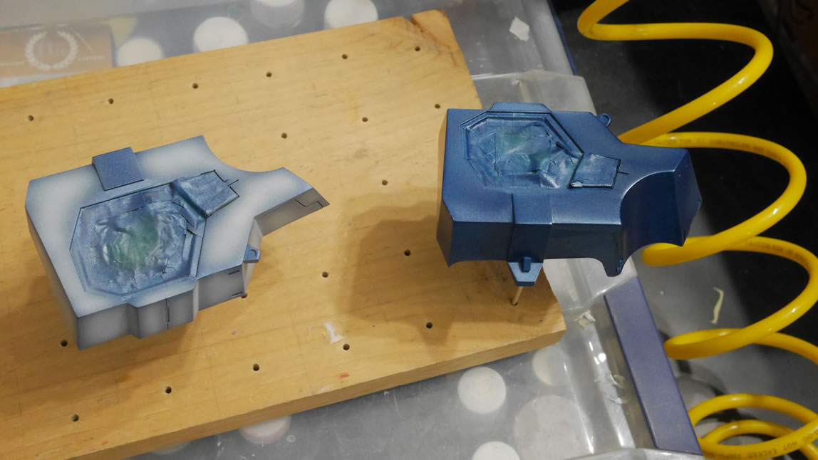
October 28, 2019: Now that I’m done pulling a bunch of casts, time to actually build the the damn thing. The difference is that I’m building and painting up the first 3D printed bust piece which is the bigger bust in 4 major pieces. Since the original 3D Design isn’t the best designed part, when it was printed, those mistakes in the design are also printed out so those will need to be addressed.
Jumping right in, the pictures belowed show the printed flaws that need to be sanded and/or filled. There is a lot of sanding and some light curing putty to level things off along some of the flat surfaces that didn’t get printed perfectly.
More about the build after the jump.
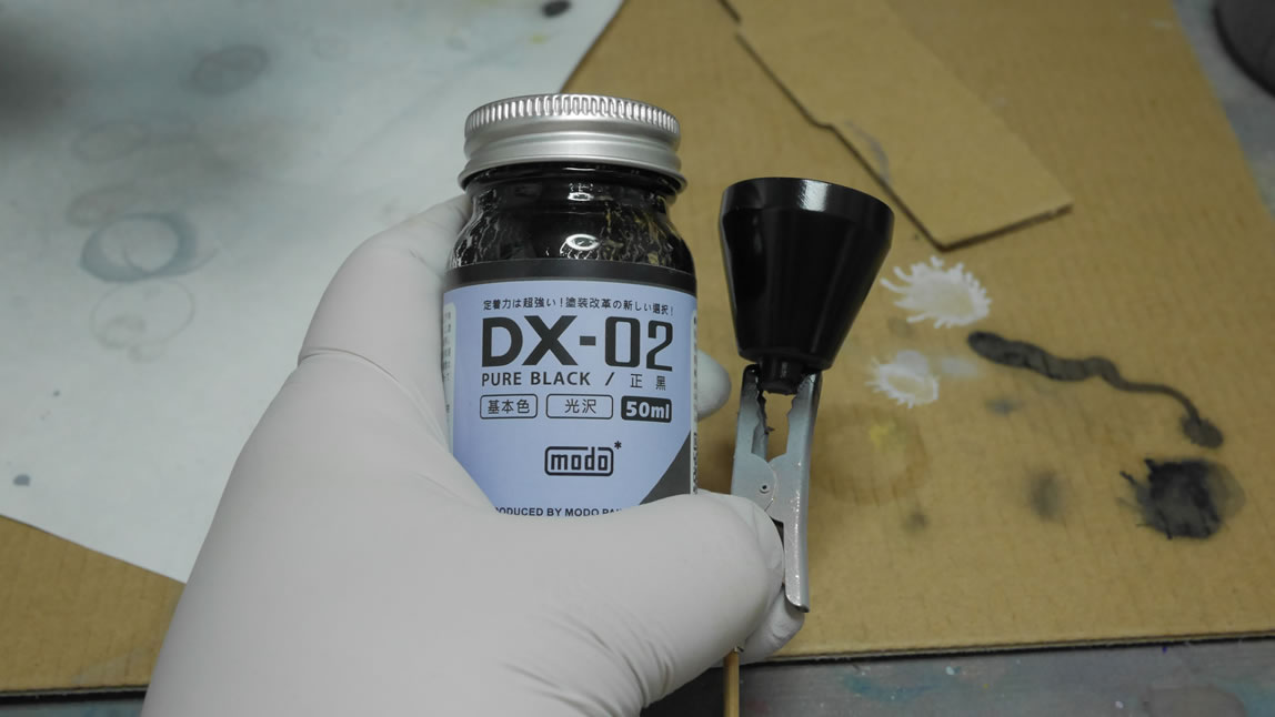
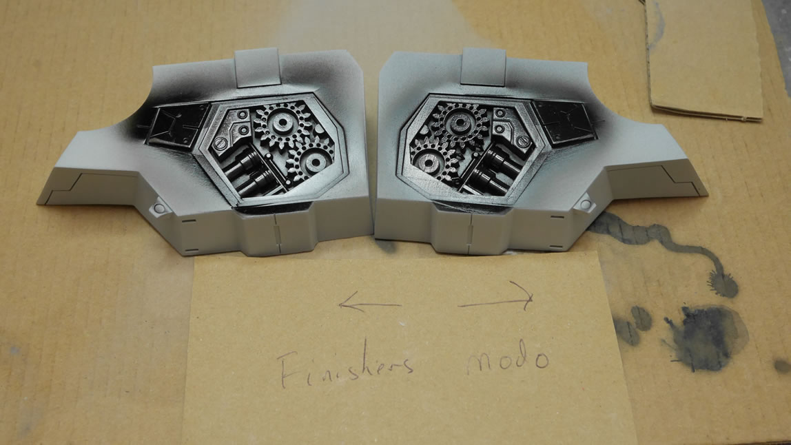
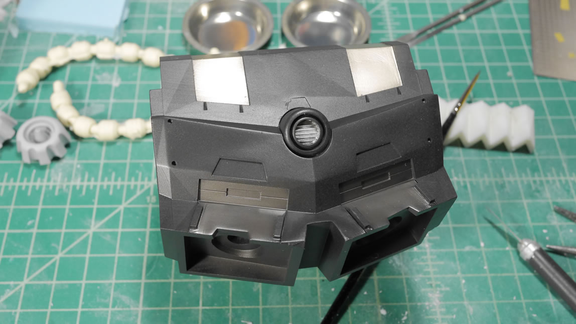
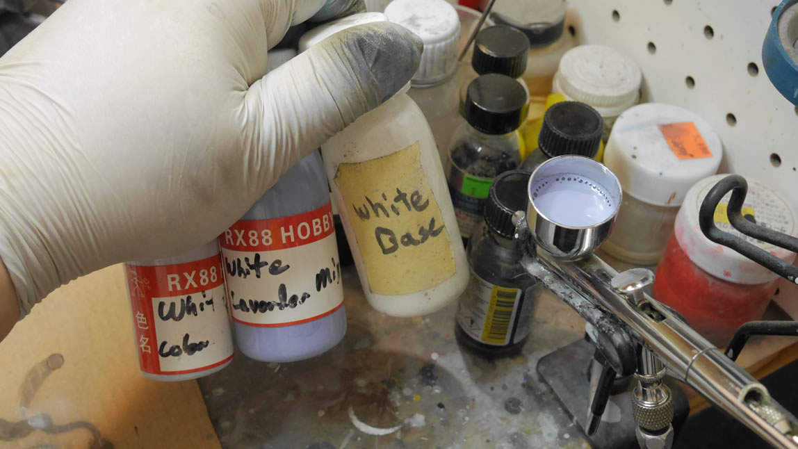
My wife went to Hong Kong back in August and she had a day to do some model supply shopping for me so I had her pick up some Modo Color paints. So here’s the gloss black used as a base. It looks pretty good and goes on as well as Finisher’s that I’ve been mostly using. Smell is slightly different, I think the Finisher’s has a stronger smell. Once the paint was cured, I sprayed a layer of alclad stainless steel.
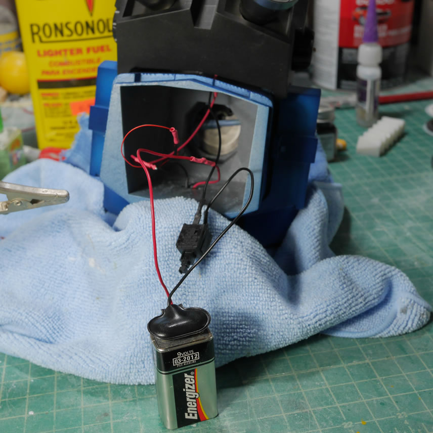
The thrusters are easily finished up and the internals were painted with alclad burnt metal. Assembled with the LED inside and the clear middle piece, the whole thing is glued together using white glue and fully assembled the whole thruster bell. A quick test with a battery and the light comes through and the bells look pretty cool.
The rest of the bust is primed after all the sanding fixes to check for more surface issues. There were a few, so once those were fixed, I moved on to actual paint. The next picture is a direct comparison of the gloss black from Finisher’s and from Modo. I don’t see a difference. Pictures may be difficult to completely discern, but I really did not see a difference in the cured paints. They sprayed on the same and the performacne is identical.
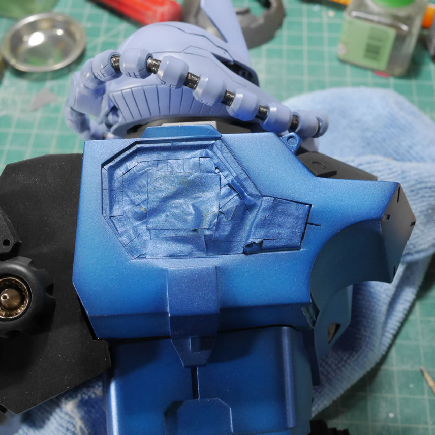
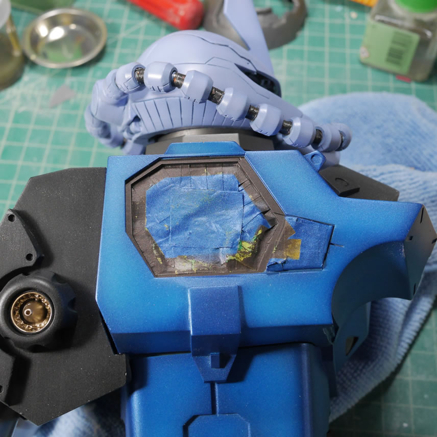
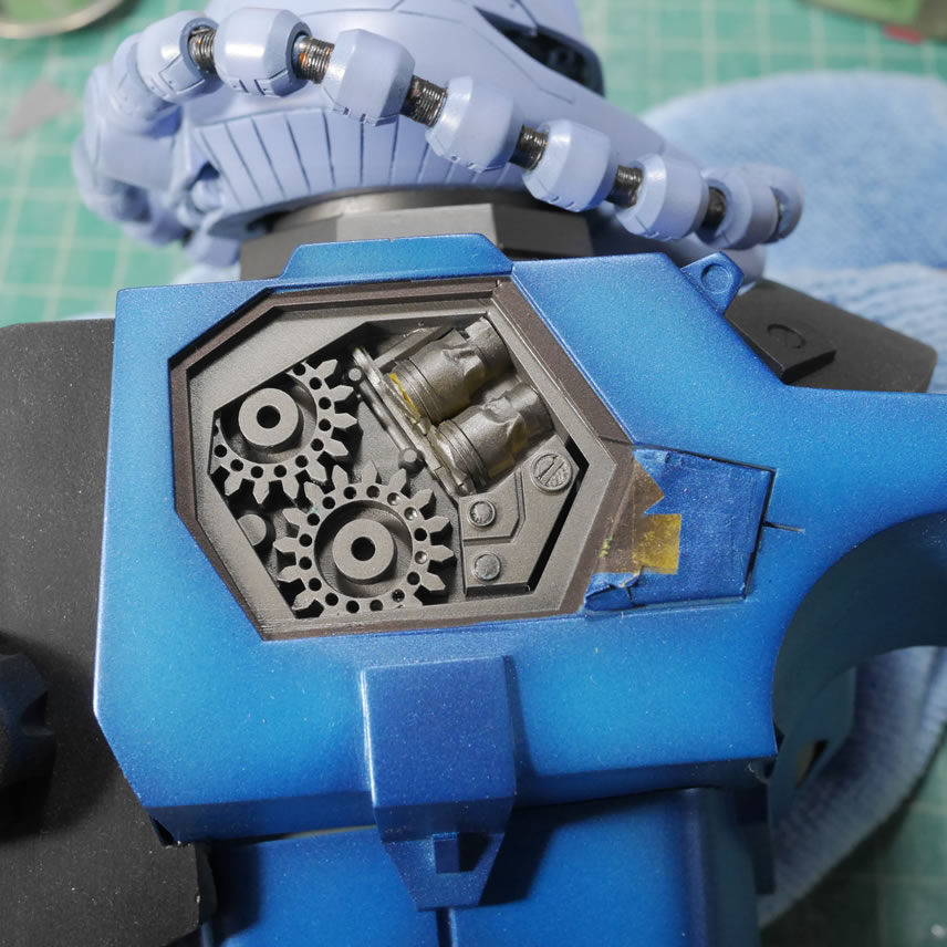
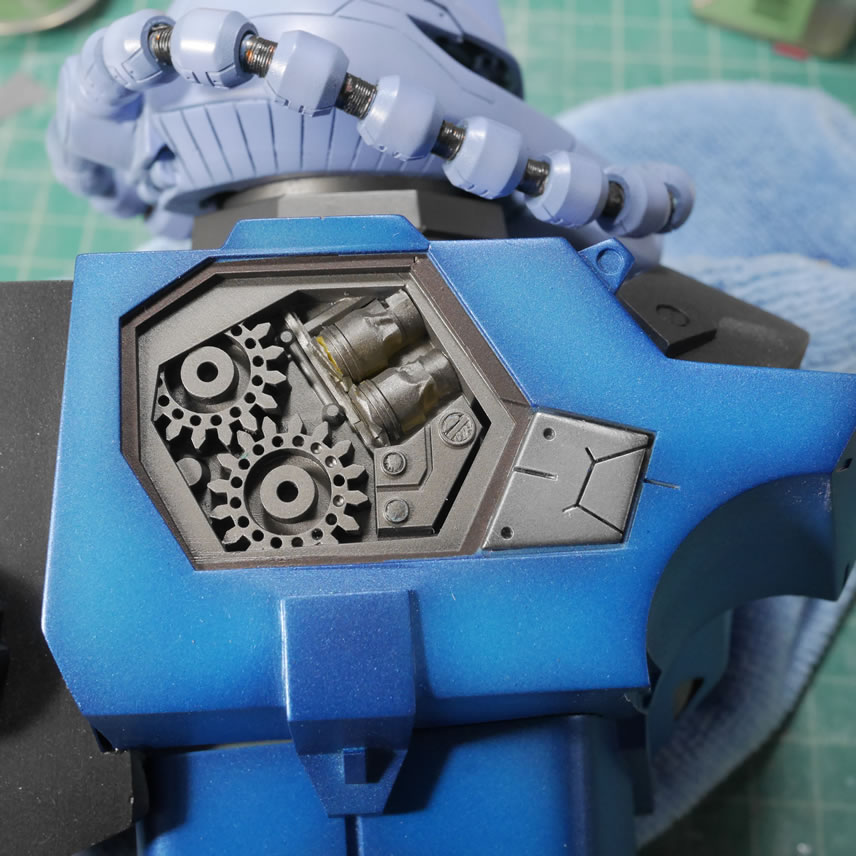
Once the black is cured, I can get on with detail metallics. The process is simple, spray the lowest level of detail first. So the pipes were painted in alclad polished aluminum. That area is masked. Then polish brass is sprayed. That is masked, then alclad steel. Masked, then burnt metal for the side extruding piece. Masked, then alclad exhaust manifold, then masked again. Some of the bigger areas get a layer of liquid mask as a catch all mask so that I don’t have any missed overlapps in the tape.
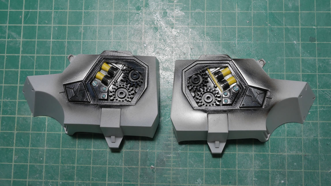
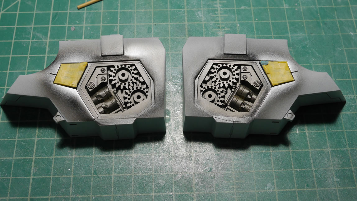
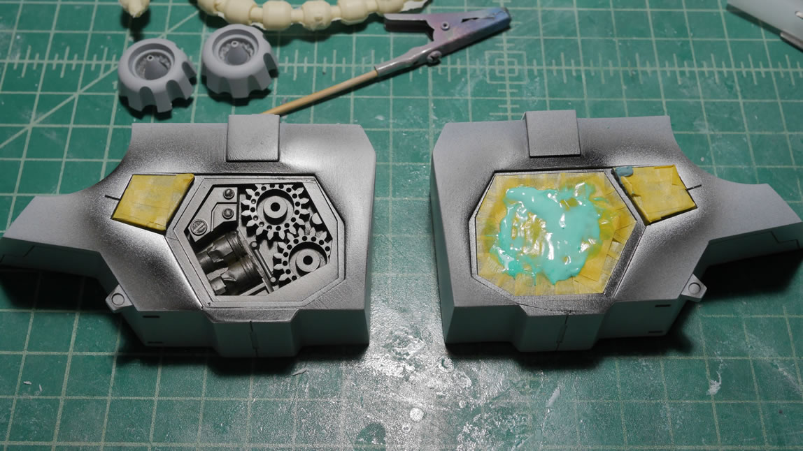
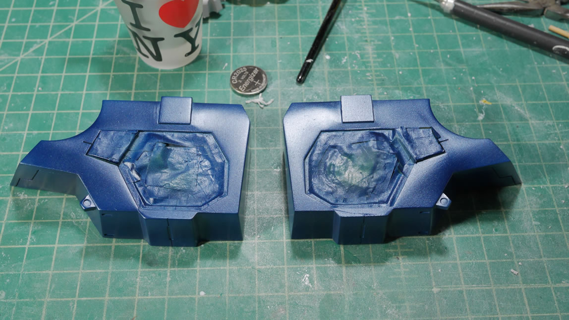
Once the metallic details are masked off I can spray on the base color. For this, I used Finisher’s metallic indigo. Seems kind of a waste, but I like using a darker tone from the final color as a shading element. The side chest pieces are painted first and the head is put away for the time being. Over the cured metallic indigo, I use mr white base and create a heavily shaded effect. I like a very lightly shaded effect, but this is an intermediate color lift, so this is fine for now.
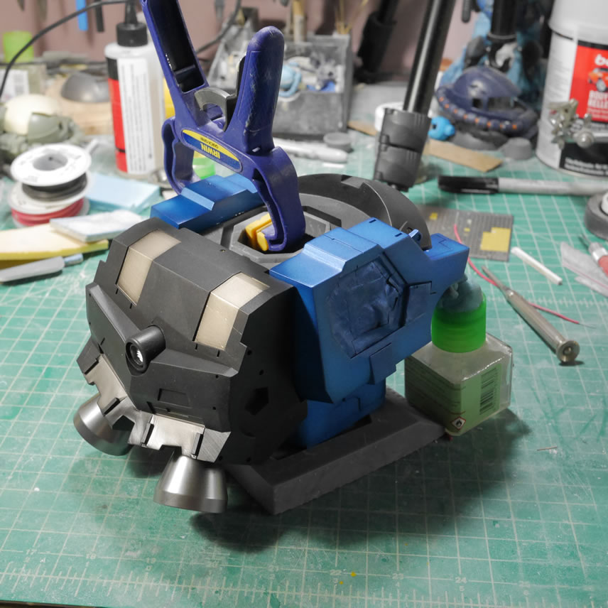
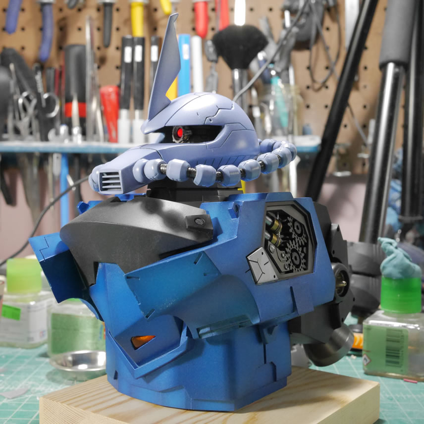
While that is curing, I got the backpack painted. Some details are painted with alclad burnt metal, alclad steel, and alcald polished aluminum. Same technique as earlier, lowest layers get painted first, then masked. The final color is alclad burnt iron which is a flat finish paint.
The main chest block is painted and the side chest pieces are painted with leftover touchup paint from my ’11 WRX. World Rally Blue. It has got a little metallic in it and worked very well thinned with mr color thinner. I did a quick little live stream when I painted up the chest and side pieces. It is a quick 20 minute long video and does some quick explanation of basic airbrushing technique, you can check that out here:
The backpack is painted. Time to glue everything together. The clamps are helping to keep the parts in place while the glue cures. I used a 5 minute epoxy for the glue. Notice that there is a hole in the top of the backpack. I drilled in a hole through this piece and into the chest piece so I can drop in a pin to help hold the pieces together while the glue sets. This also helped when I was test fitting and temporarily holding the parts together.
This may be a bit counter intuitive since I already spent the time painting the whole backpack. Once the glue set, the areas surrounding the hole are masked off so I could fill the hole with some putty, sand, prime, base coat, and repaint that area. I do this because painting the backpack piece by itself is much easier than painting the whole piece once it is glued together. In hindsight, I could have used magnets as the contact points, but it sorta wastes the magnets as the parts won’t be coming apart once glued. I do this kind of thing alot with resin figures. I paint the part, glue, then fix the seam, then repaint. This is an order of operations thing.
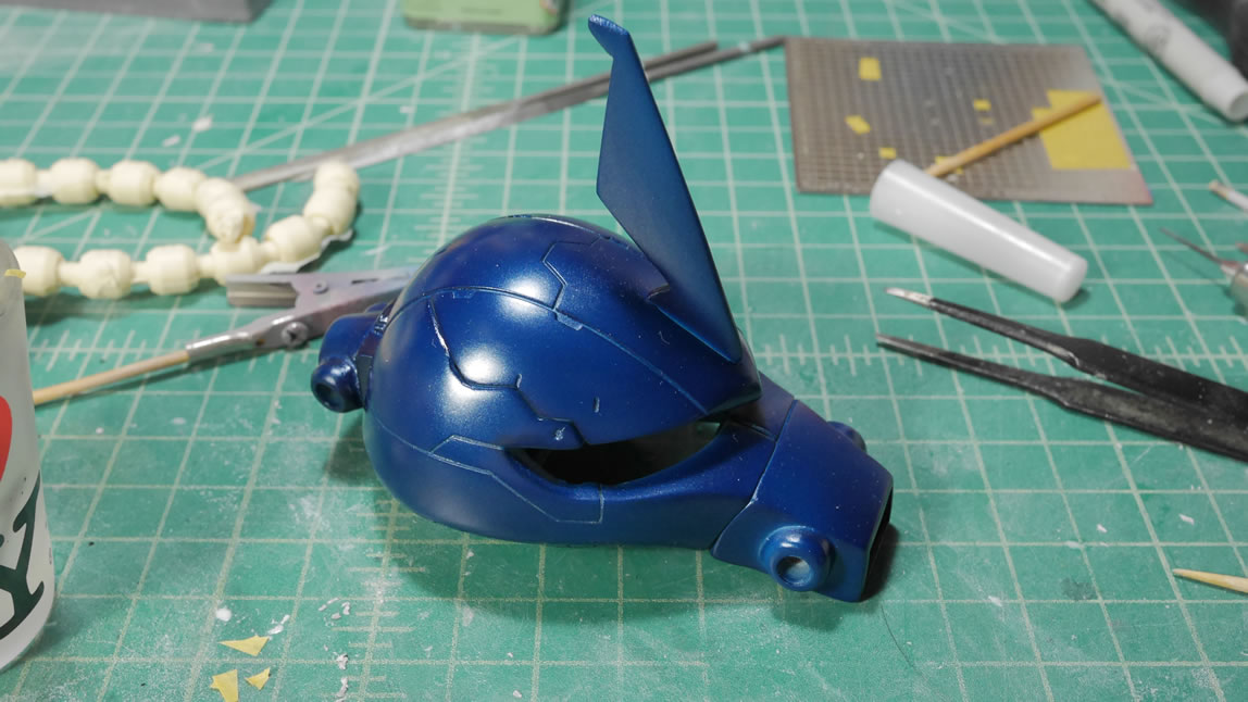
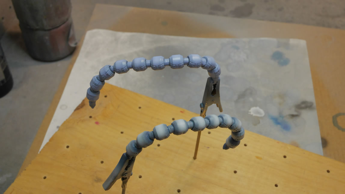
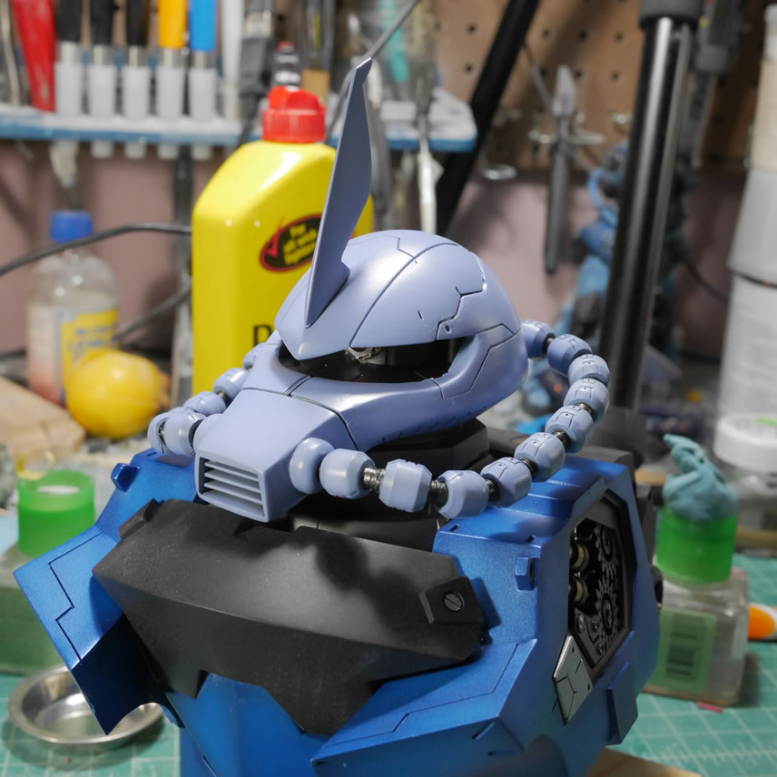
I set the head peiece aside for a while since it is being painted a different blue tone than the chest sides. Also, I didn’t finish cleaning up and painting the cables so if I painted up the head piece first, it increases the chance for tonal variance between the head and the cables. I want the color tones to be as uniform as possible. The wiring between the cable joints are painted with alclad steel. Those areas are masked off with parafilm then primed and based coated with the metallic indigo. Once that was done, the same mr white base is sprayed as a heavily shaded effect.
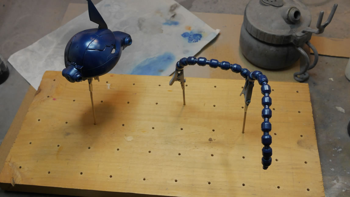
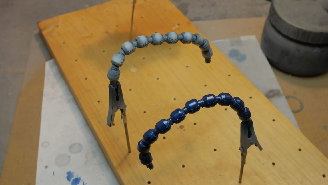
I found some leftover premixed colors that were close to what I wanted but not quite, so I combined those colors a bit to create the final color for the Gouf’s head and cables. The light blueish lavendar is sprayed over the parts and effectively blends in all the shaded areas. The whole thing is thrown into the dehydrator and cured for a couple of hours.
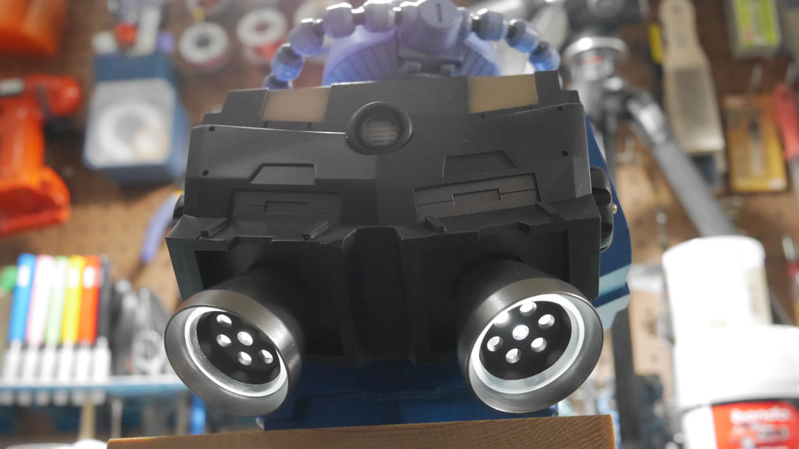
Lights. There are LEDs in the thrusters that run through the backpack and connect to one another in parallel. There are two white LEDs and once connected in parallel, I have one set of wires running from the backpack through the chest block and down the big empty space in the middle of the body. The front of the chest I have the same white LEDs poking out from behind the clear orange details also connected in parallel then factored down to one pair also in the chest. With the head done, I combined the internals for the head and dropped the wires connected to a red LED for the mono eye.
If I had used the same white LED for the mono eye, I could have just wired everything up in parallel and be done with a single 3V battery power source. But since I have different color LEDs, I need to wired this up differently. The three sets; backpack, front chest, and monoeye need to be wired in series with the switch and battery source. Since they are being wired in series, I can use a larger power source so I use a 9V battery. In parallel, the same leads are wired together (positive with positive and negative with the negative). In series, we are creating a chain os sorts. Think of it as a loop. We start with one positive and connect that to the next device’s negative end. That next device’s positive end is then connected to the 3rd device’s negative end, and so on. For the switch, the negative end from the last device is connect to one lead on the switch. The other lead on the switch is connected to the negative end of the power source wire. The positive lead from the power source is connected directly to the negative leade of the first device. I have a ring instead of parallel lines. This works to power all the lights as the individual power requirements for each bulb is added up and the whole ring is powered.
If I tried to wire this in parallel and run a single 3V power source, only the white LEDs (or the LEDs that consume the most power) will be lit. This is something to keep in mind when you string together LEDs of different siez, types, and colors.
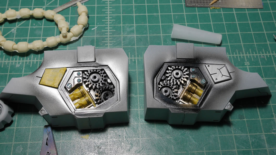
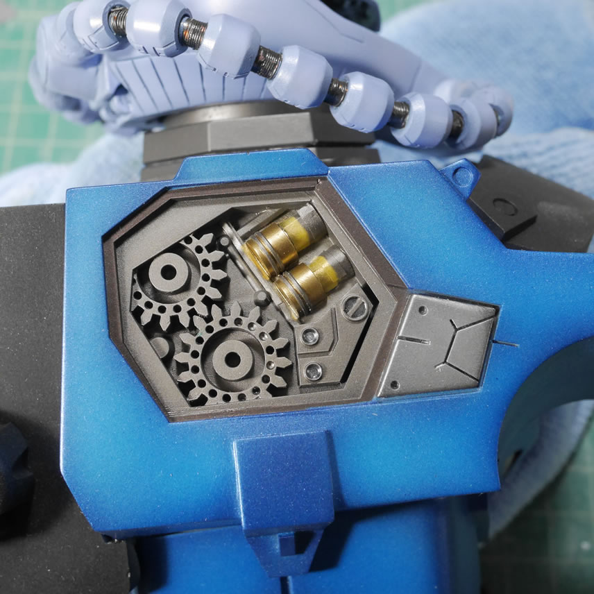
Eveything is soldered together and heat shrink wrapped to isolate everything. Time to recusively unmask the side chest internal details. Layer by layer, the mask is removed revealing the next lower layer until everything is unmasked.
It is quite satisfying to remove the mask and now have any paint lift.
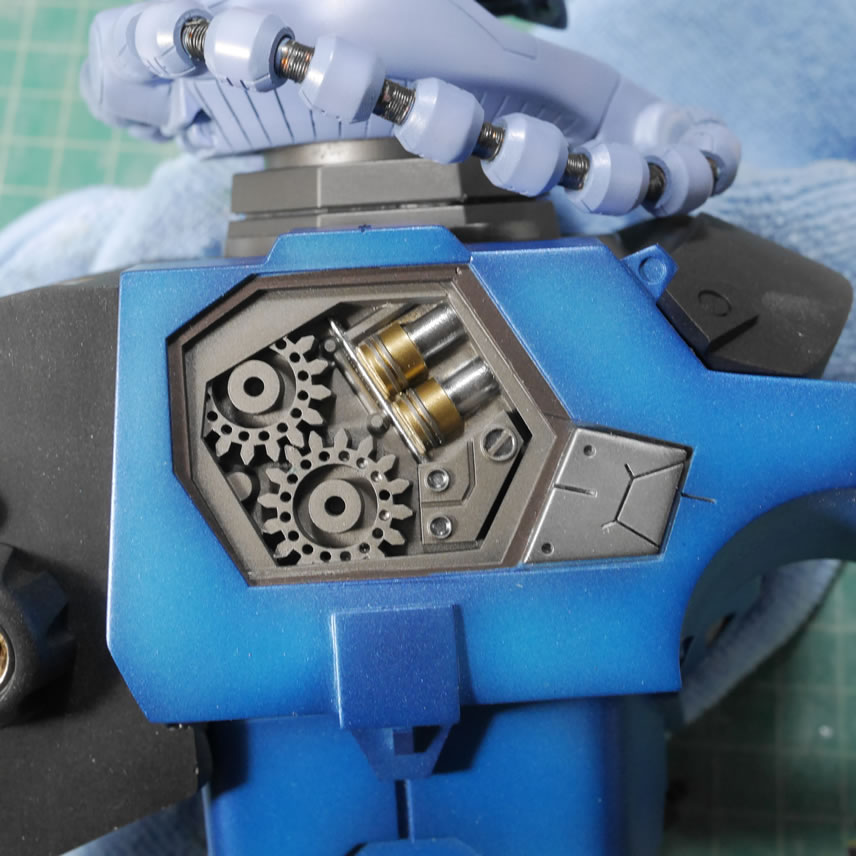
The lighting is tested and everything works and all the wires, switch, and power source is hidden inside the body.
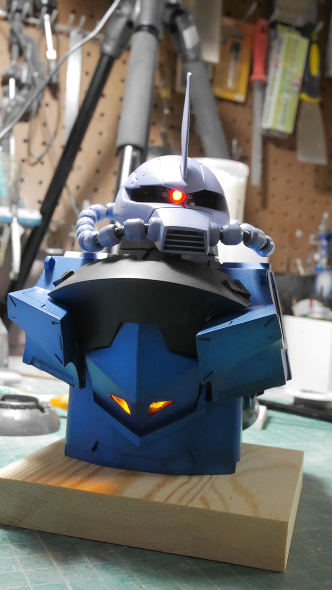
And here we have the size comparison with a 1/100 MG Zaku II and the 1/144 Gouf Custom. This damn thing is sizeable.
Next up will be the clear coats, some decals, panel lines, and final clear coat. Come to SCGMC in 2 weeks to check it out in person!
Completed pictures can be found here: Completed Gouf Custom Exceed Head Conversion with Bust