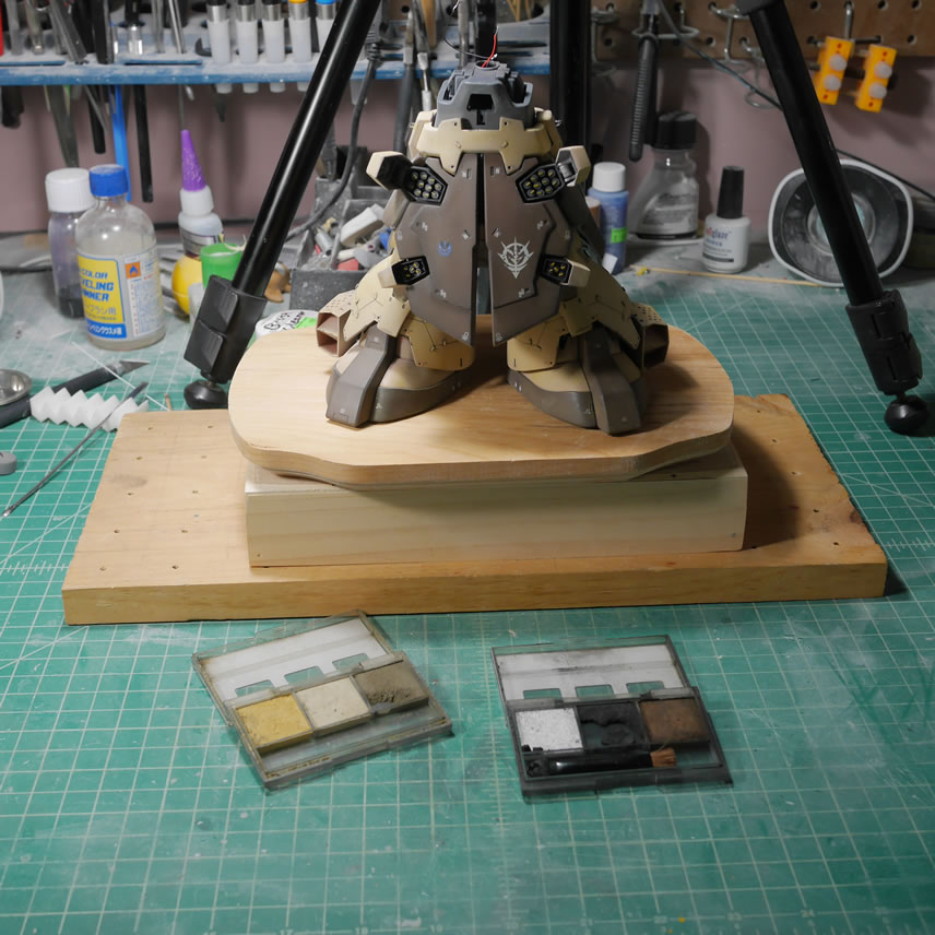
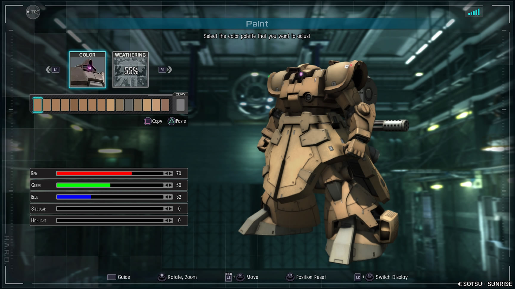
Feb 1, 2019. I started this immediately after finishing the Dreissen project. Pretty much the same day. I stumbled upon the Dom Barrage, MS-09 F/Br a few years ago and was interested in doing a build of it off the MG Dom. But the reference pictures were pretty lacking and I think I found one online, built from the HGUC Dom Tropen. Using a Dom Trop really makes sense since the Barrage is a variant of the Tropen (Funf). I did find a conversion kit for the Dom F, but since I’ll have to modify that kit. So since there wasn’t a 1/100 F, next best thing was one of the MG Dom’s off my backlog. I already built 2 of these. And for some reason I have 2 more. According to a friend, one of them belongs to him, but he doesn’t build so he doesn’t mind me using it. Ok, references aside, the idea lingered in my head as a possible big project. But with the limited reference materials, I was hesitant. Fast forward to a few months ago, while playing Gundam Battle Operation 2; they released the Dom Barrage as a playable support suit. Once I got the suit, it meant unlimited screenshots from as many angles as I can get. Challenge accepted!
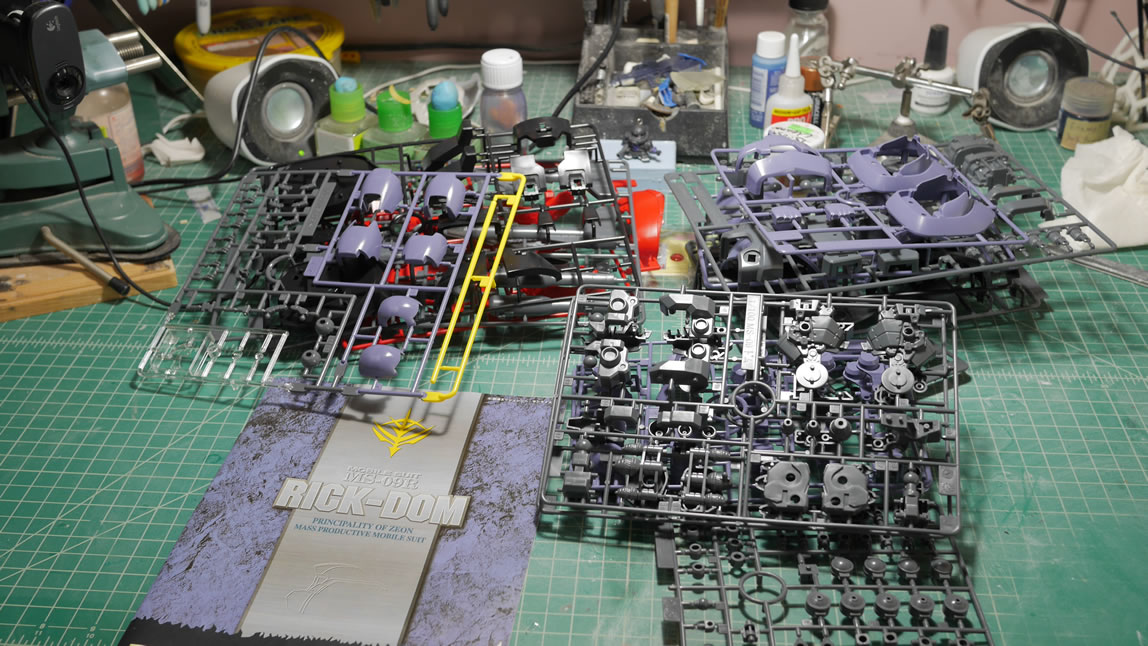
An MG Rick Dom is sacrificed for this and the project officially begins.
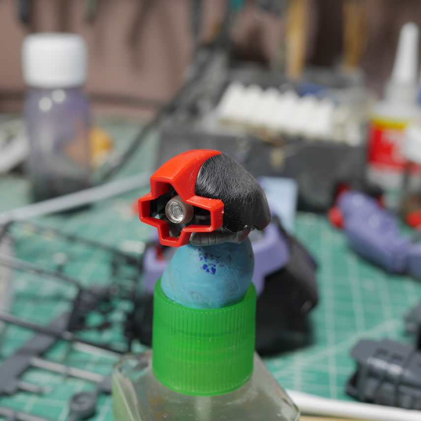
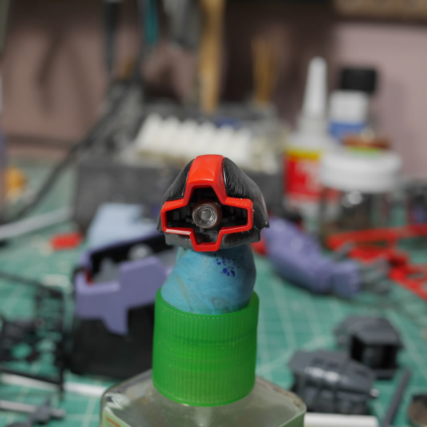
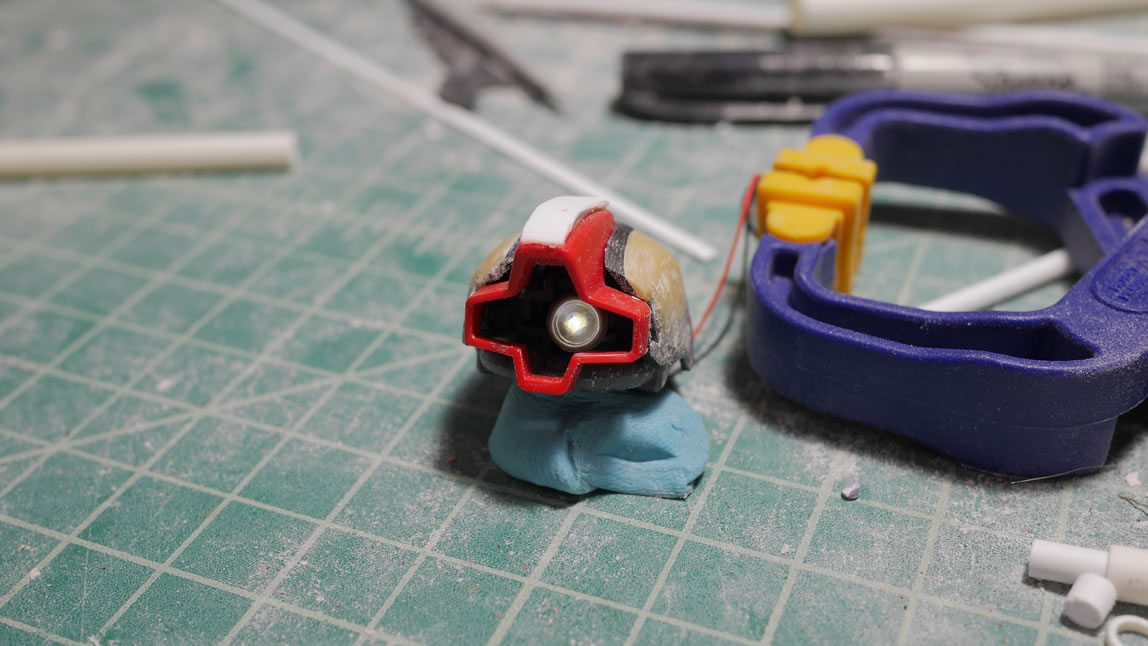
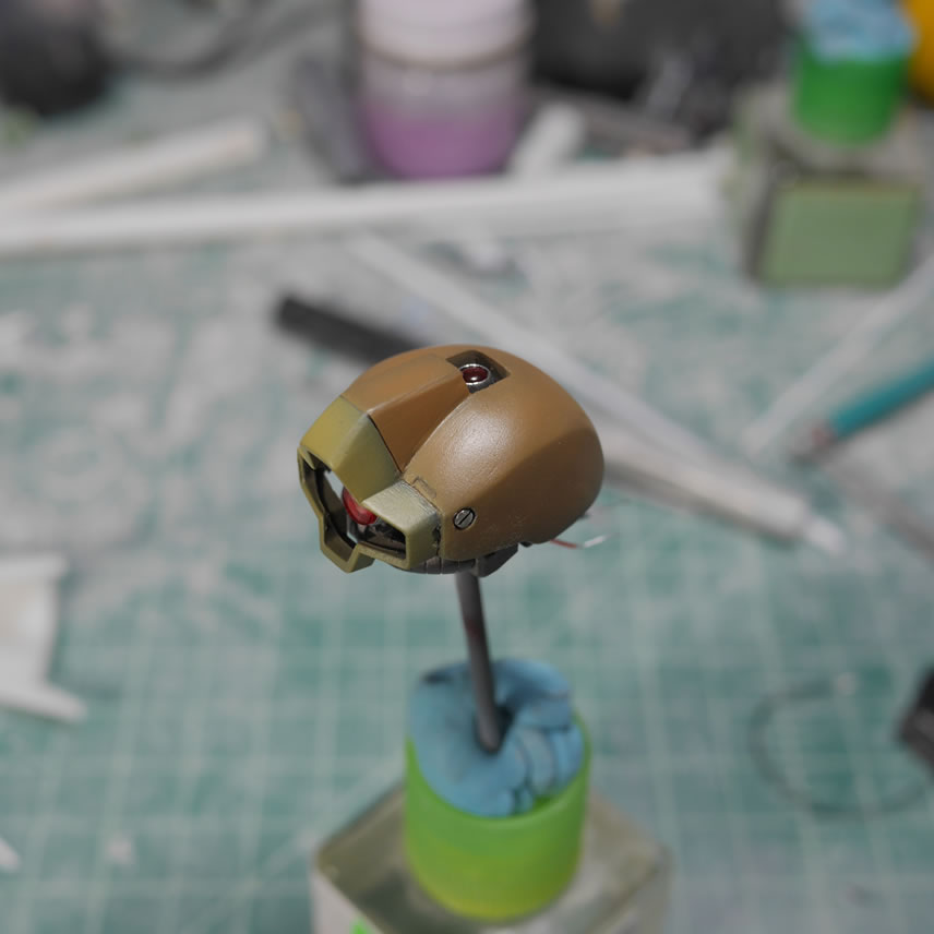
First step is the mess with the head and eyes. I will be jumping around since things need to cure and such but I’m trying to group sections to things make more sense. This is almost 2 weeks worth of work so far. I modded the mono eye with a flat U-venier from wave. I like to encapsulate the clear eye piece. The head gets a little sanding to rough up the surface.
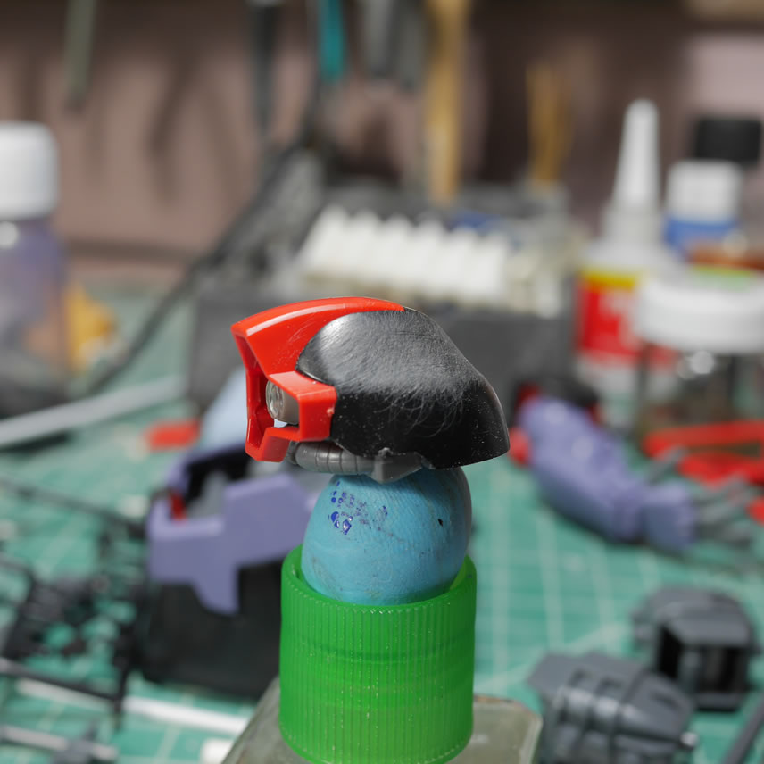
Epoxy putty is laid down to start the process of reshaping the head. This will probably be the last area I use epoxy putty as I discovered that I would end up needing way too much epoxy putty if I went down this road.
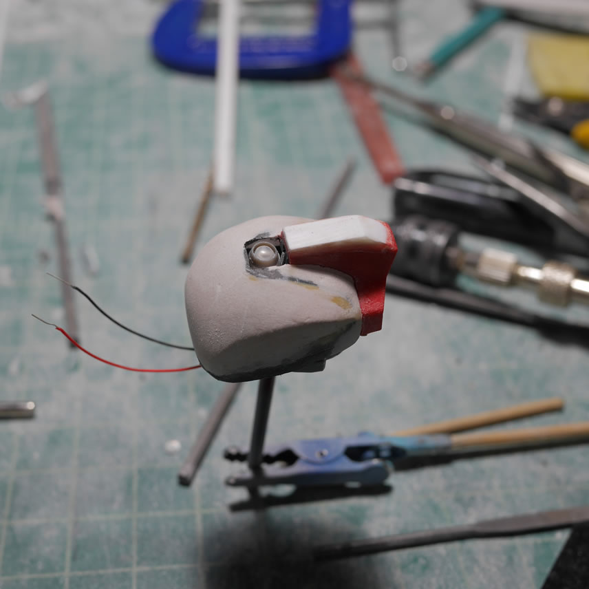
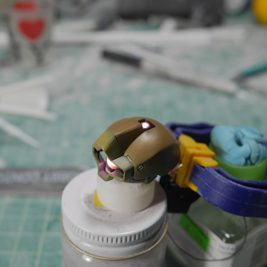
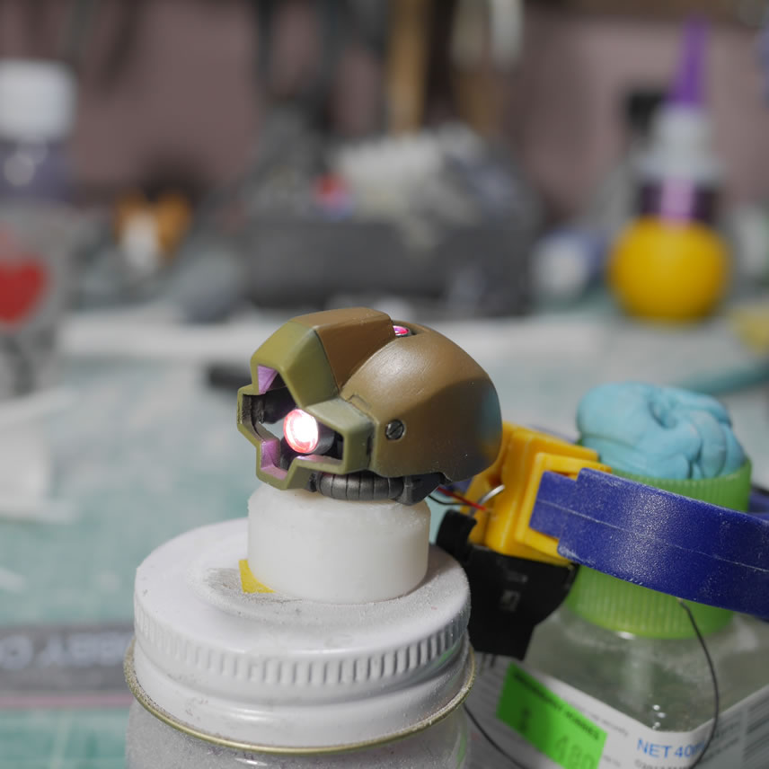
Liting the mono eye. Coming off the HGUC Dreissen size LED mods, I absolutely have to up the game and add LEDs here too. I soldered a white surface mount LED to some wires and using some styrene tubes, added to the back of the mono eye.
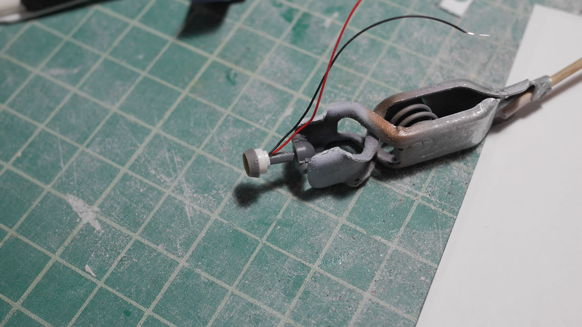
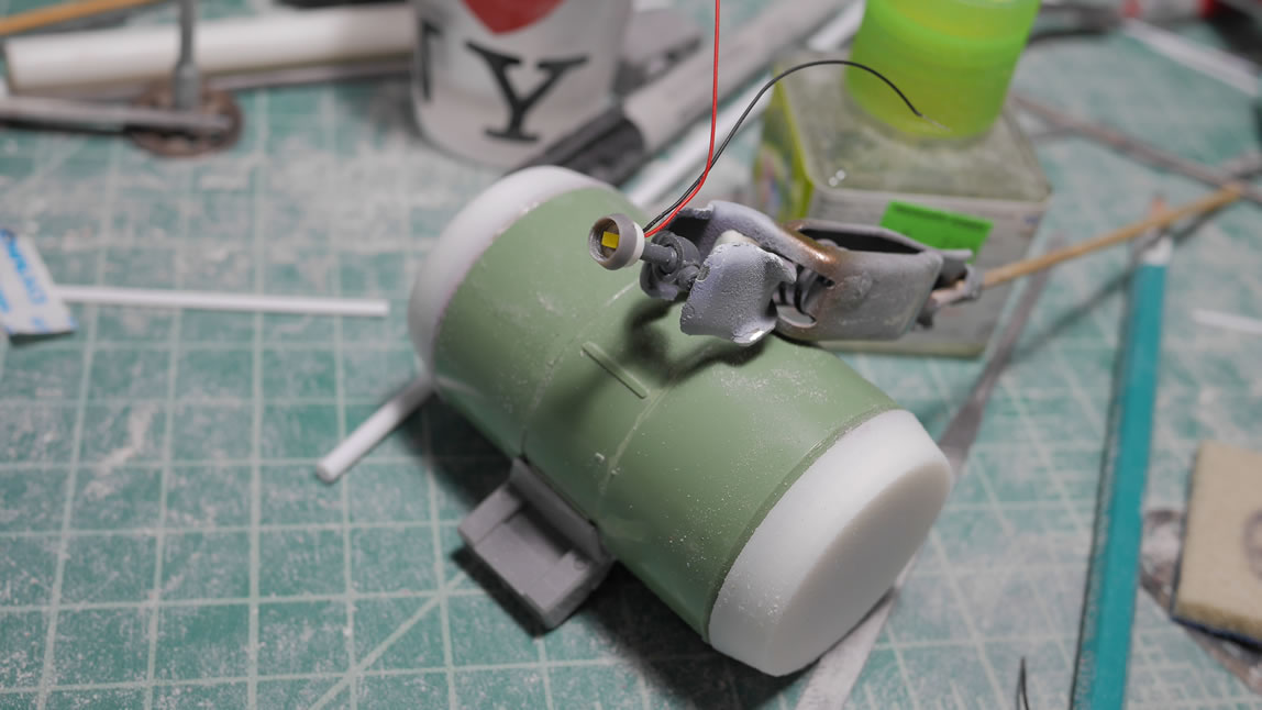
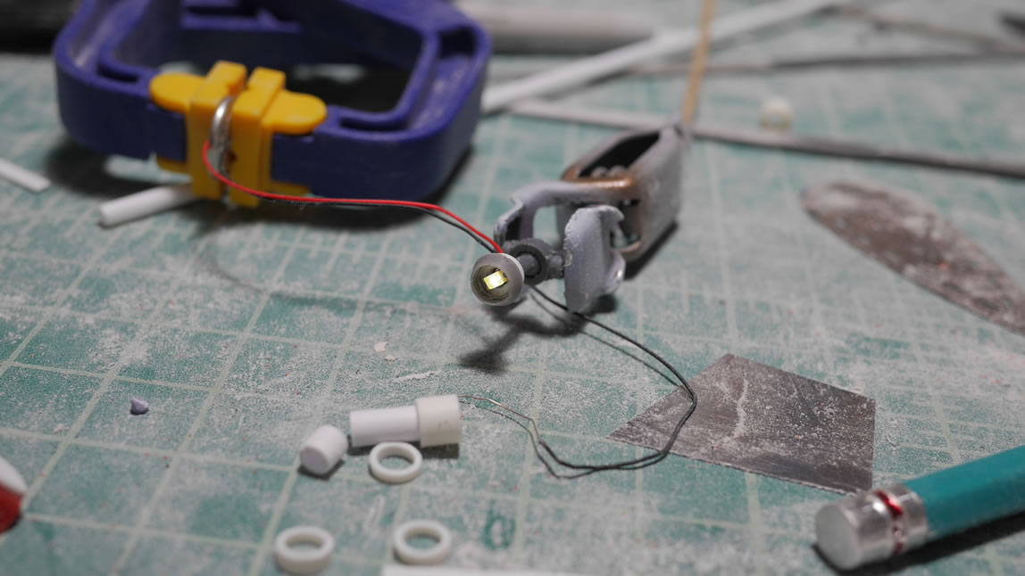
Then attaching this to the Dom’s original mono eye socket and ball joint piece, I now have a lit mono eye that keeps the move function of the original part. Never be afraid of cutting away plastic. It is only plastic. You can always add it back!
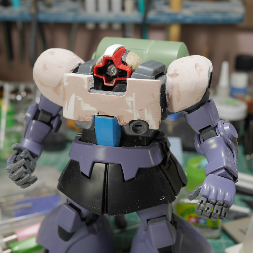
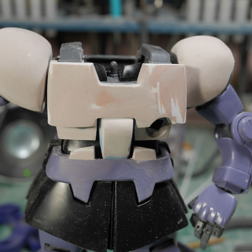
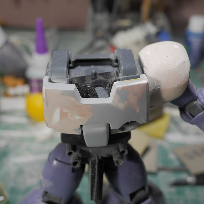
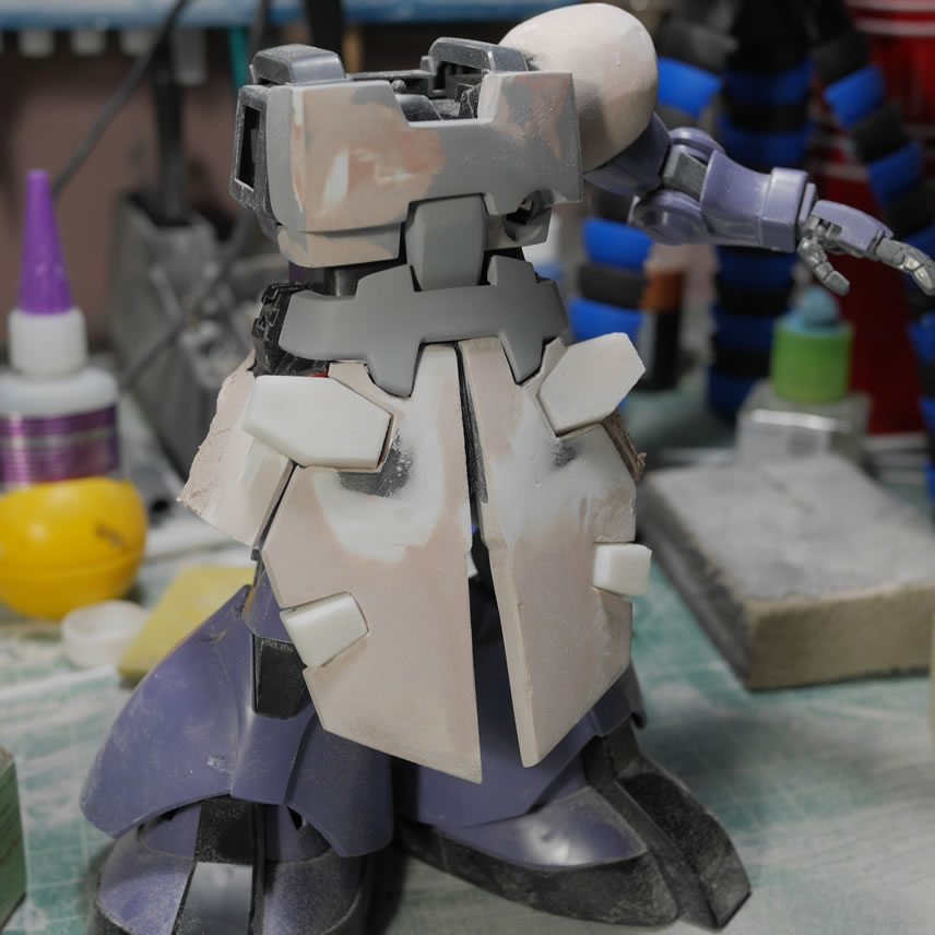
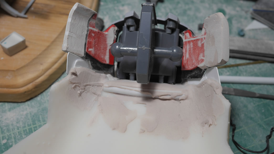
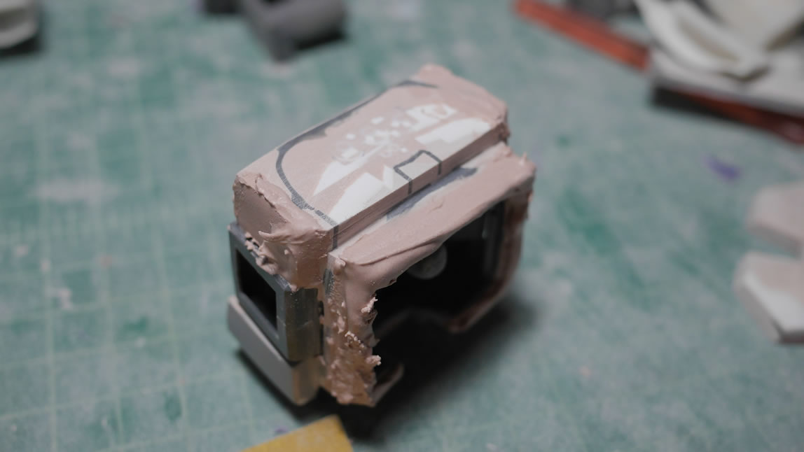
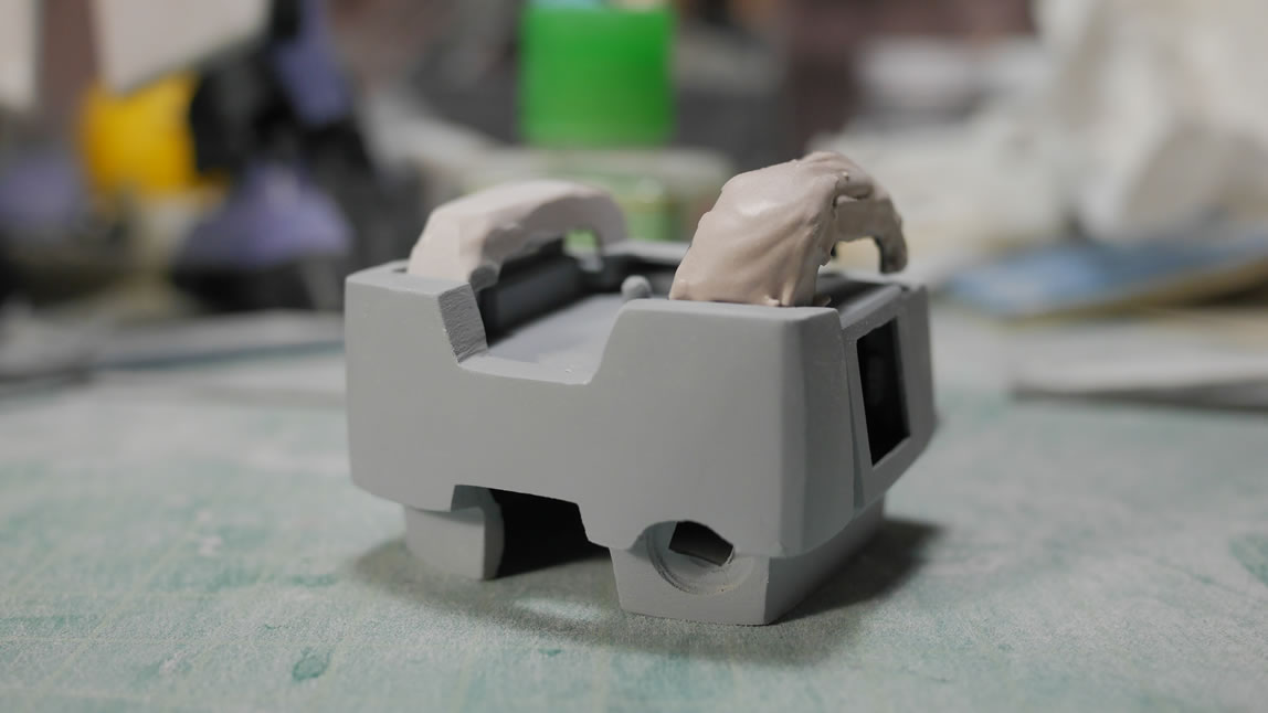
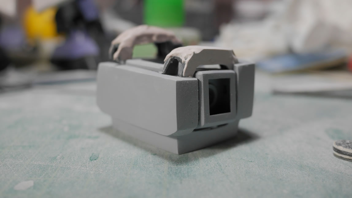
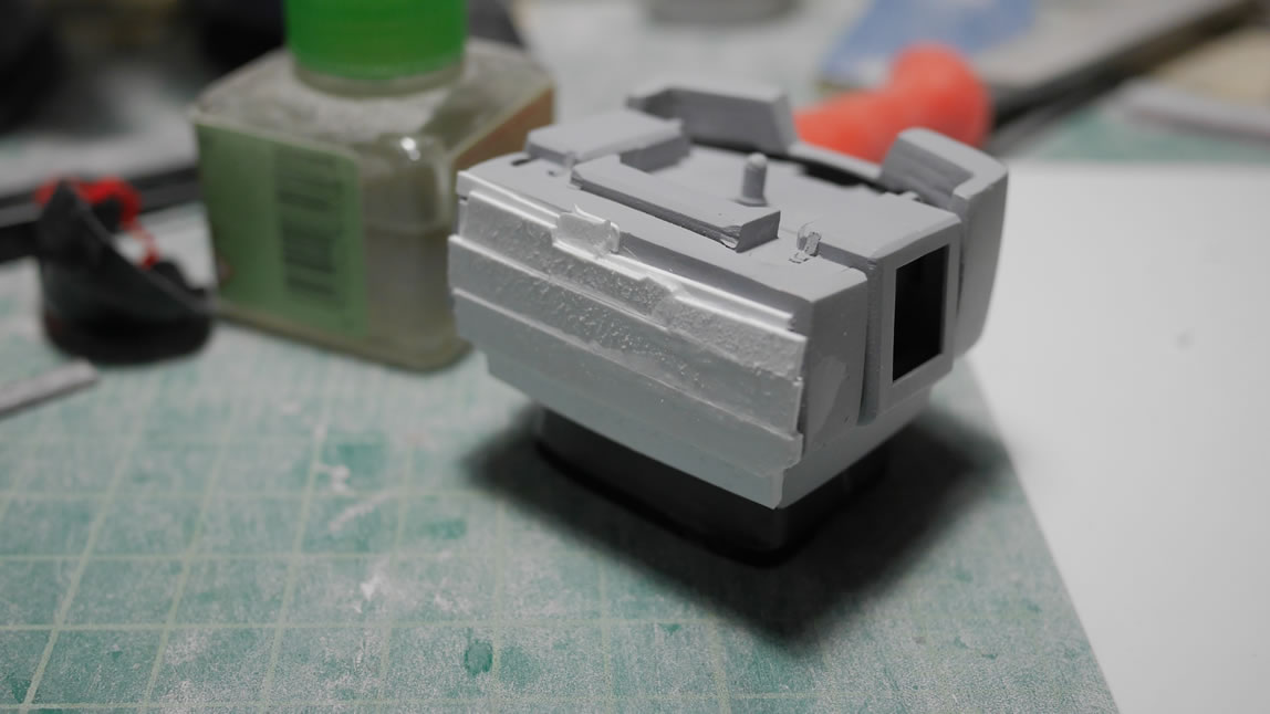
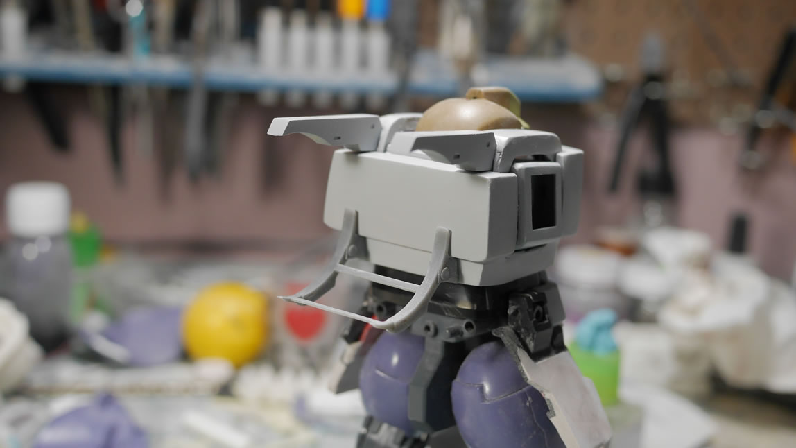
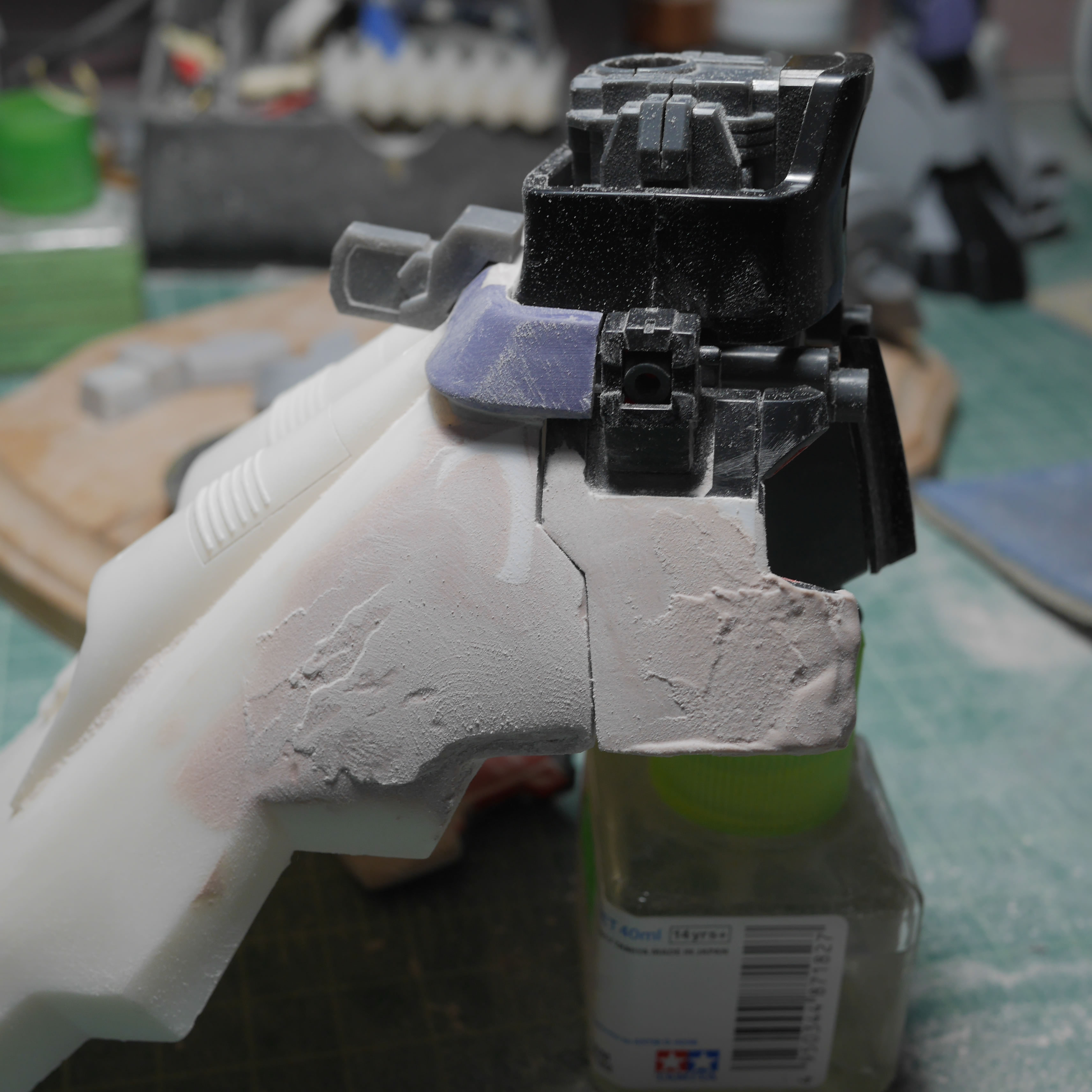
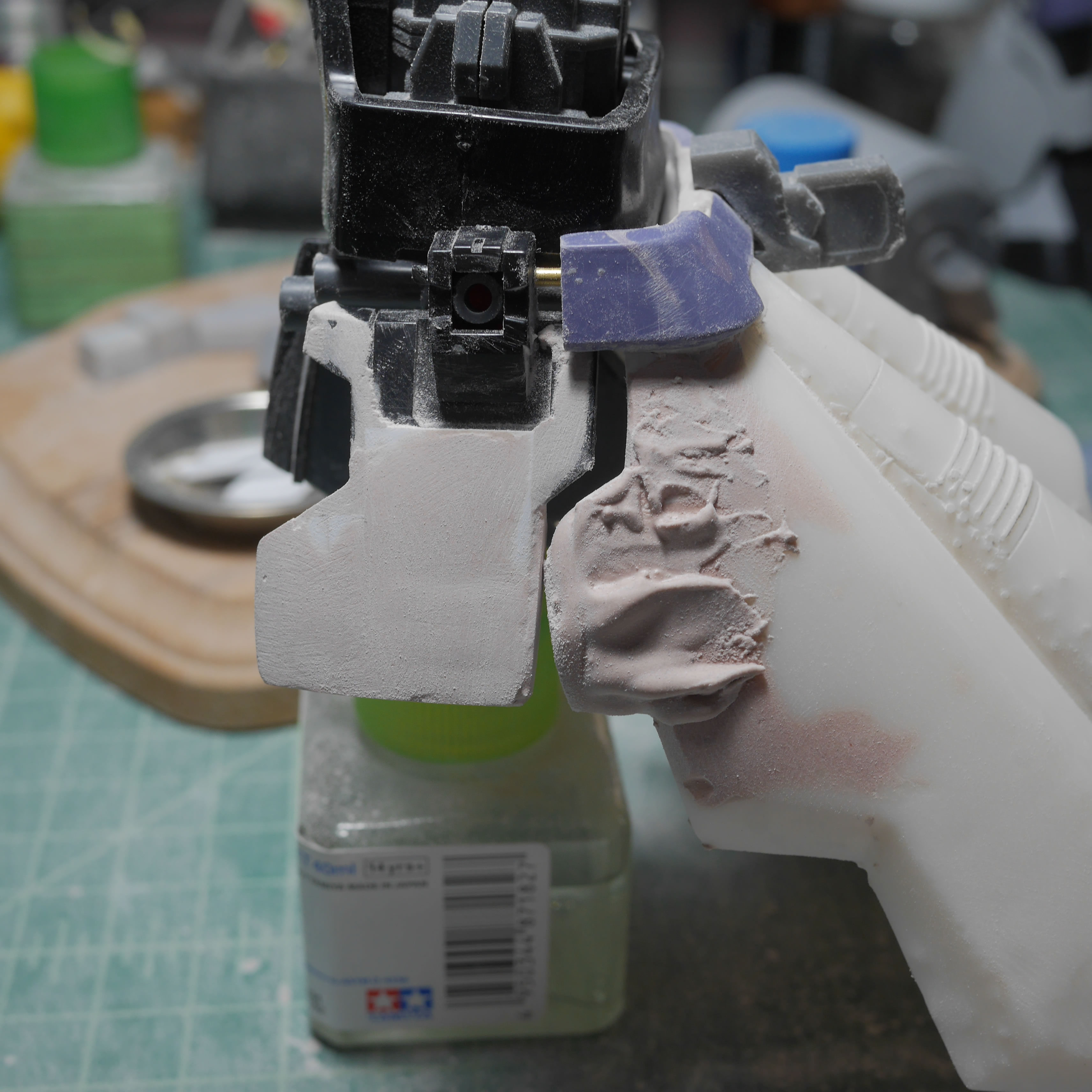
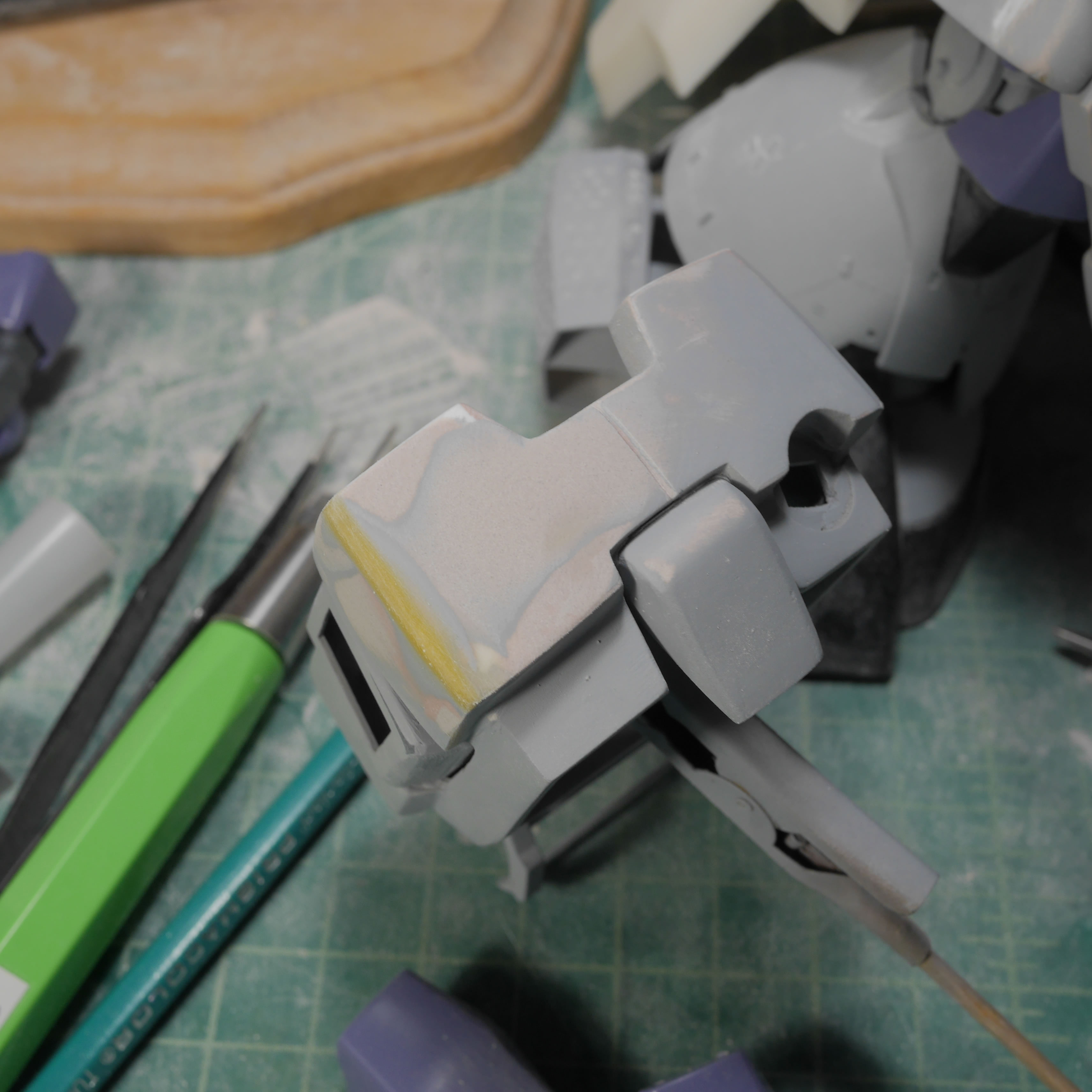
Jumping back to the upper toros. The problem with projects like this is just finding somewhere to start. I started with the mono eye because it is small and simple and once that gets going, it is easier to start sliding down the rabble hole. The chest needs some major work to reshape it. I need to add plastic here. First thing to do is to glue on strips of plastic as a structural unit. Some quick measurements are made and glue is basically poured in with cut strips of plastic.
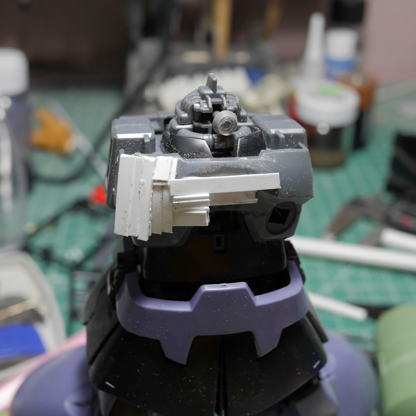
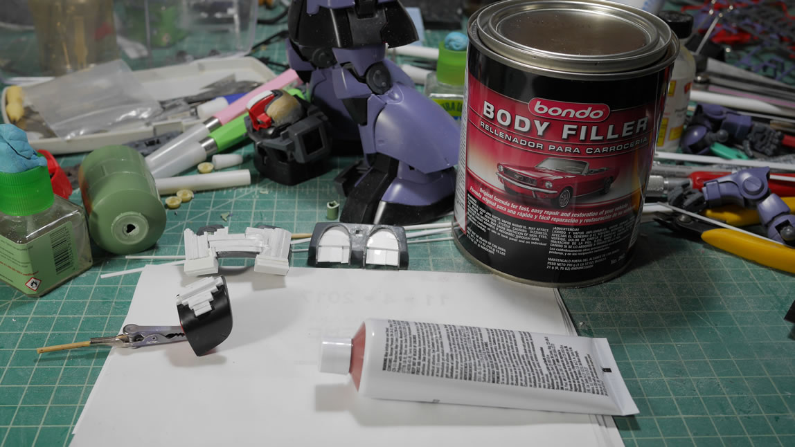
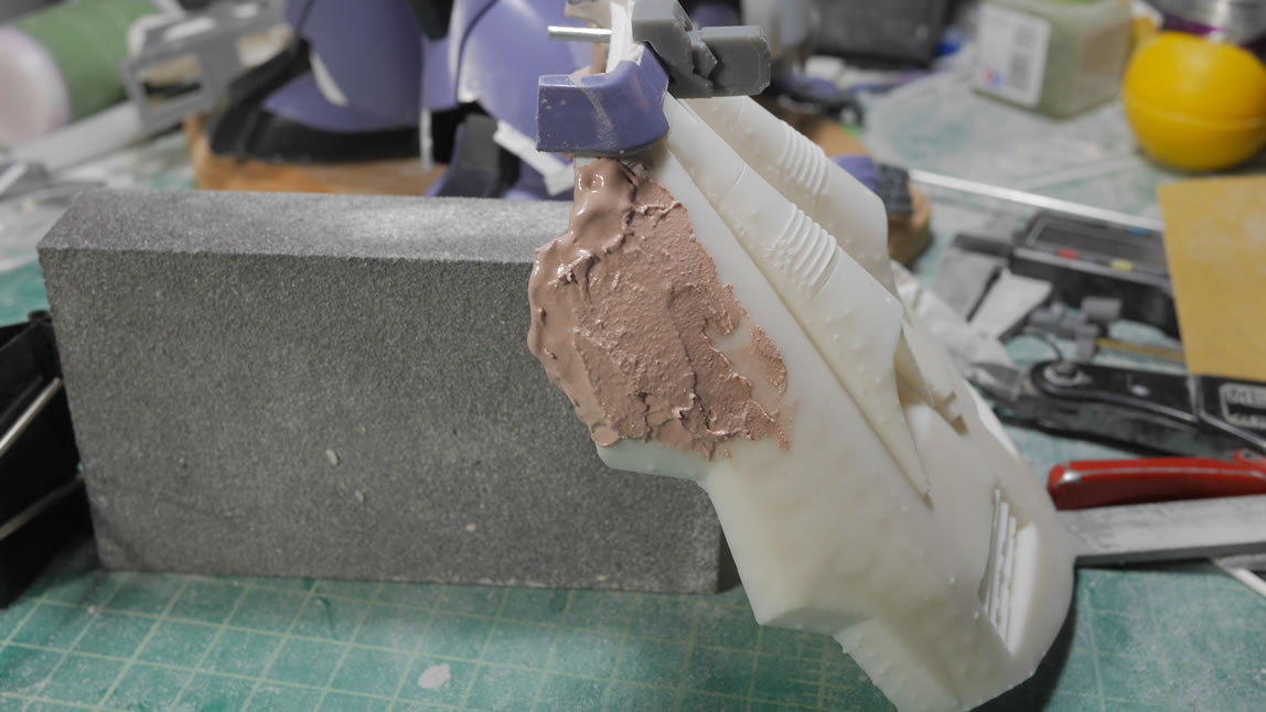
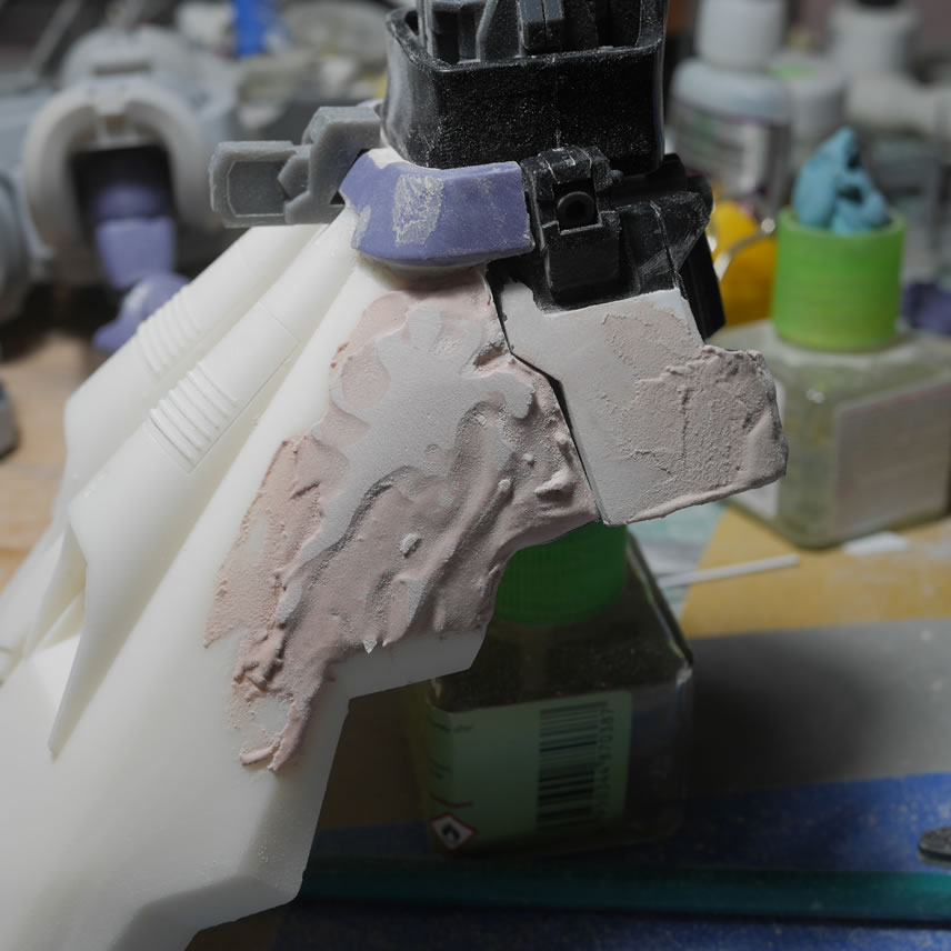
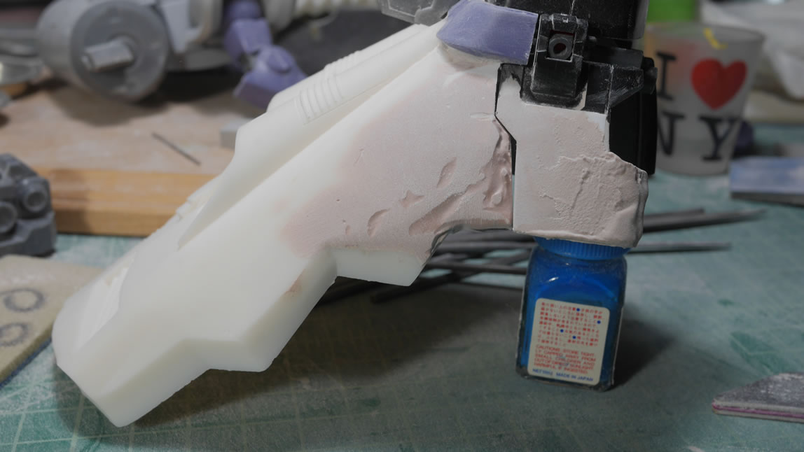
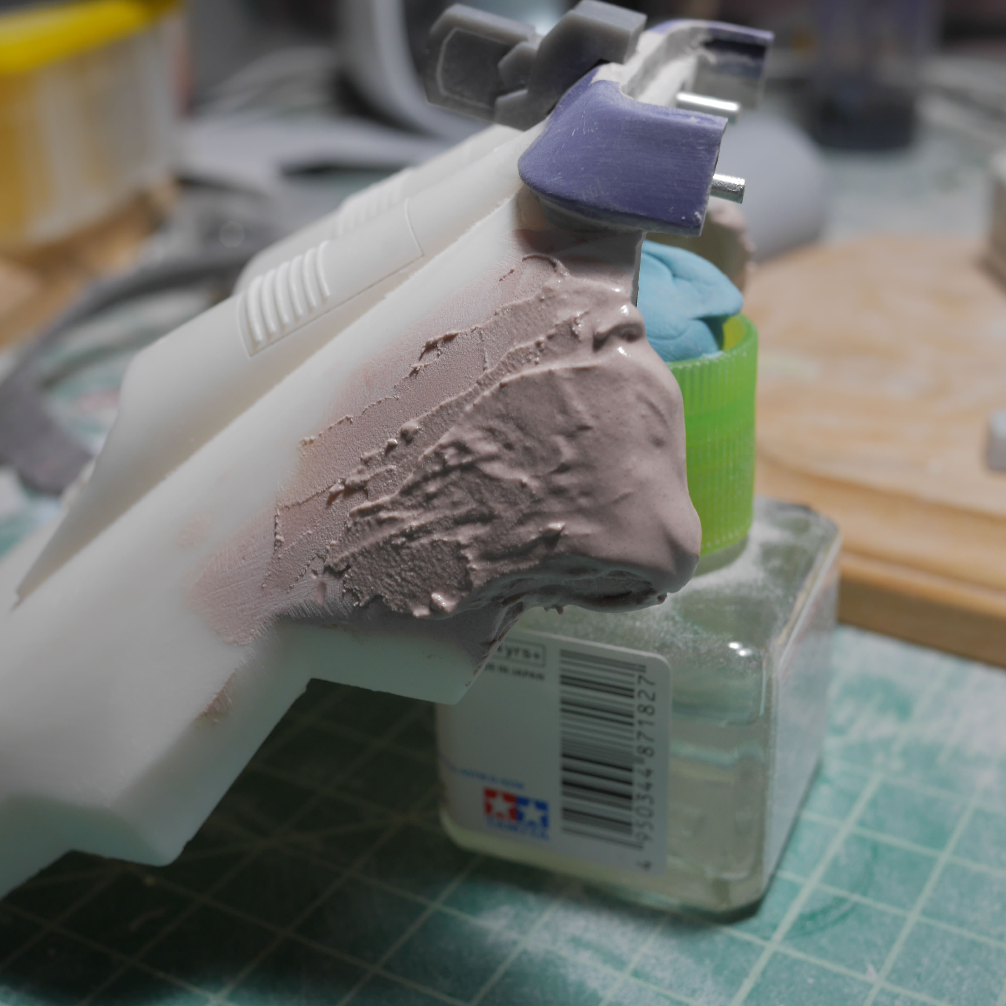
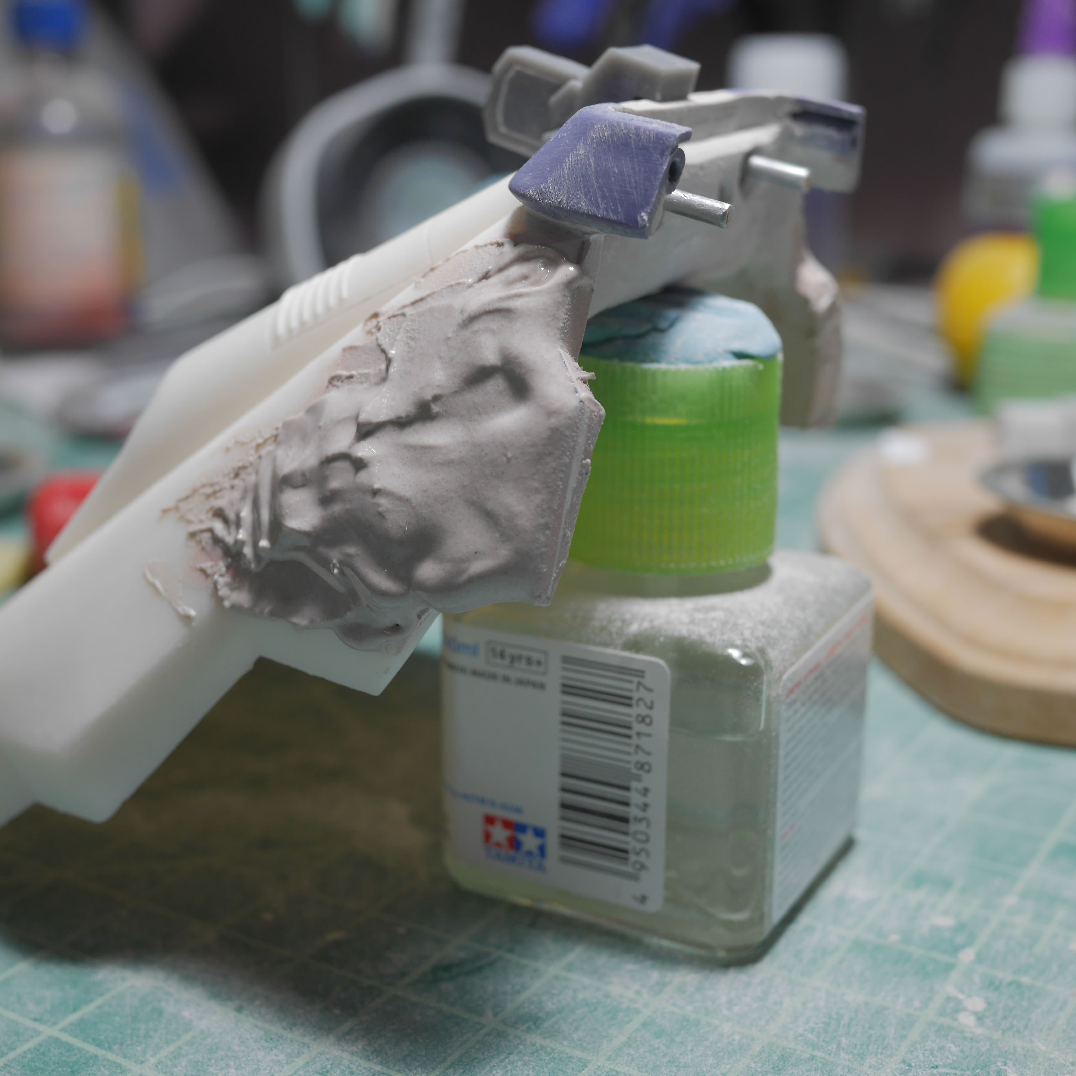
Once I have the basic structure in place, I add in the putty. Returning to the original idea that I would be using epoxy putty is completely out of the question. It would just cost too much. In the past, I have used tamiya polyester putty. This is great for doing projects like this. If you look at the linked modeler page above, the builder used some kind of polyester putty for his Barrage too. Tamiya polyester putty is a bit expensive for what it is, so time for a cheaper alternative: bondo. The stuff even smells the same and works exactly like tamiya polyester or mori mori. The putty is applied with a putty knife and pretty much cures and is ready for sanding in about an hour to 2 hours. MUCH faster than epoxy putty quick type. And sanding is MUCH easier. It is softer than resin, so some care is needed to not over sand or be too rough with the sanding.
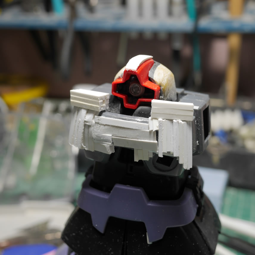
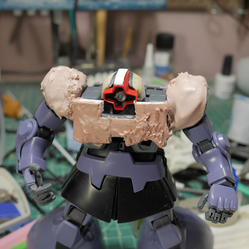
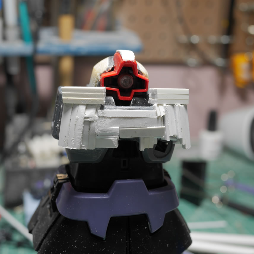
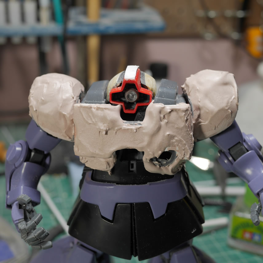
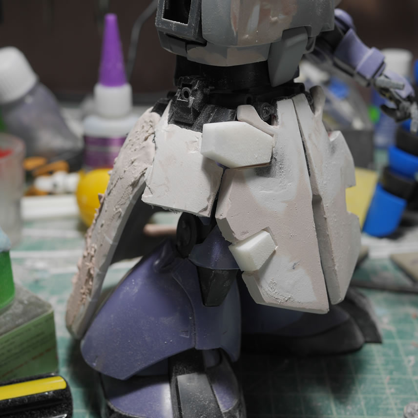
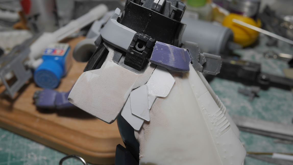
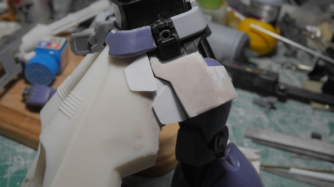
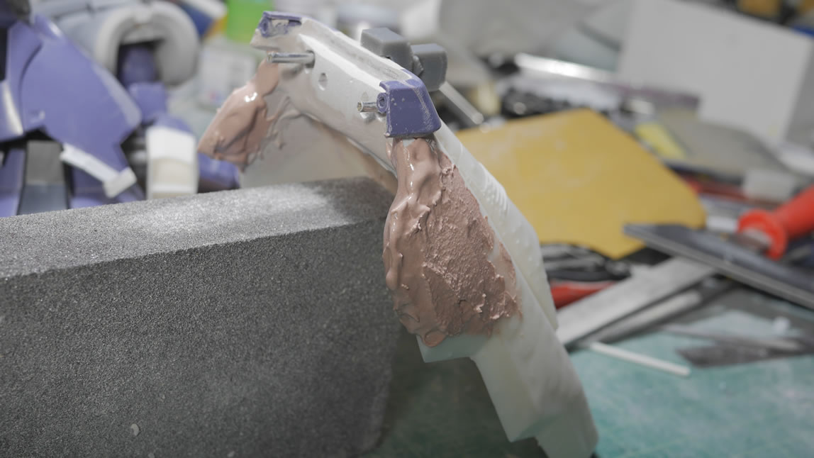
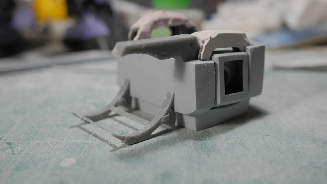
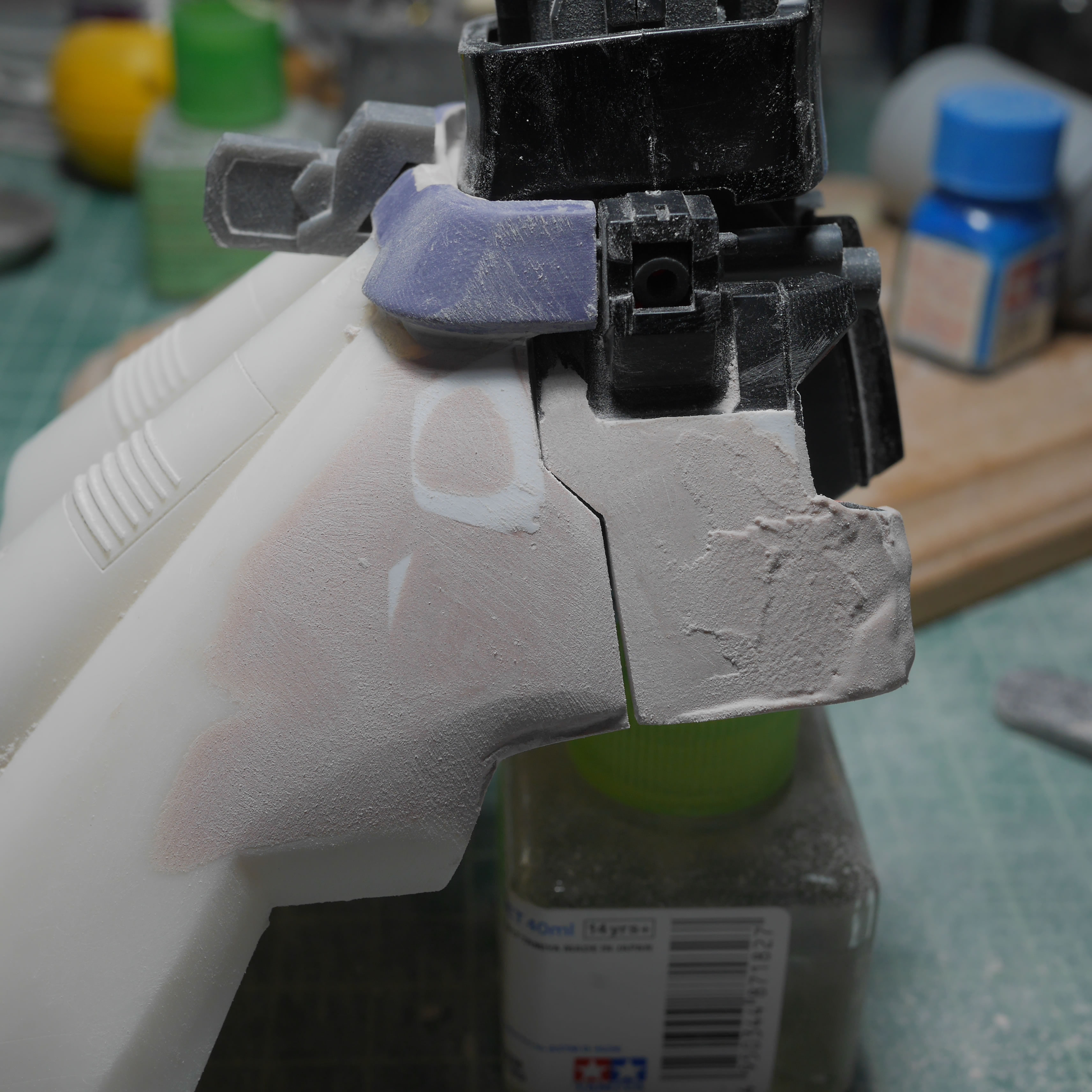
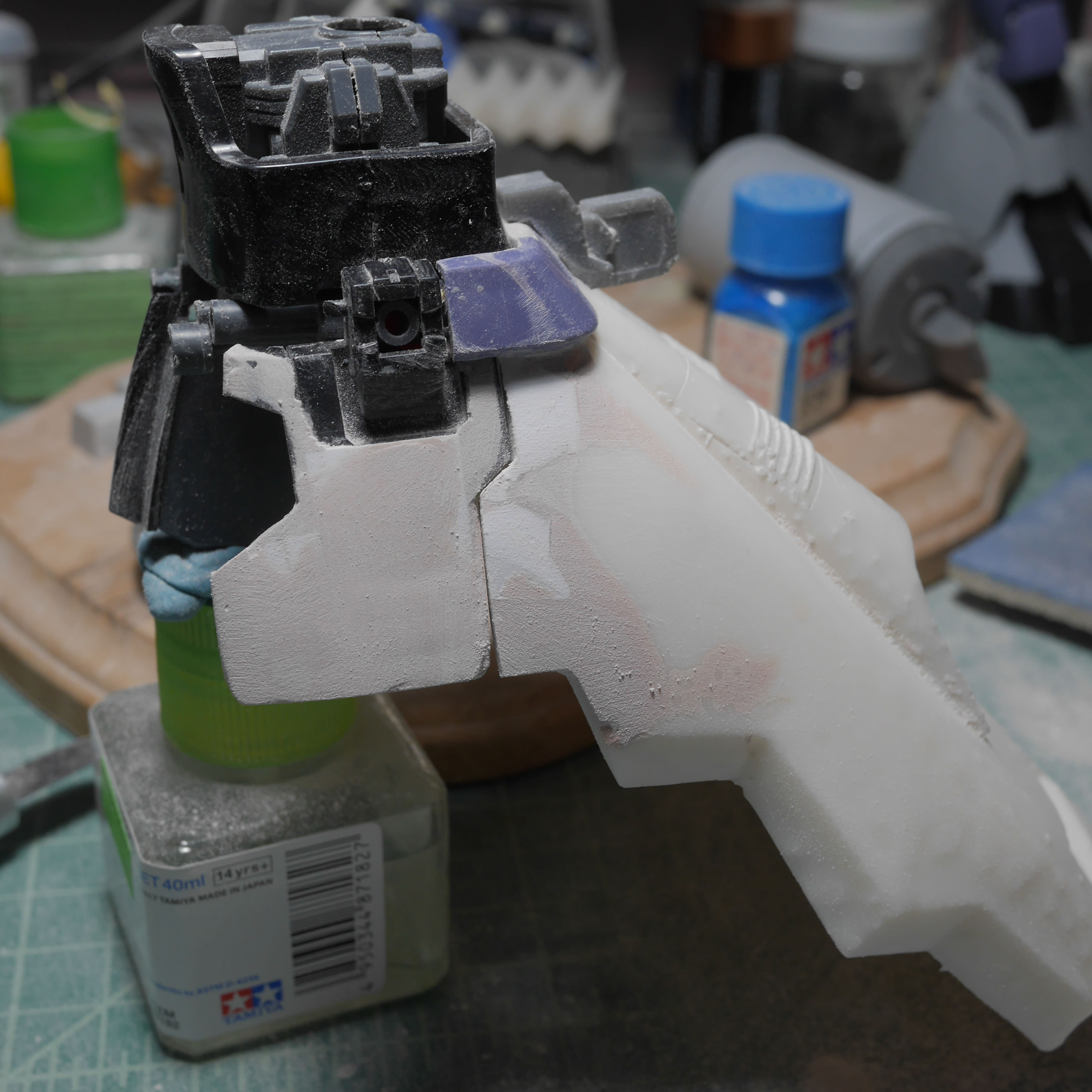
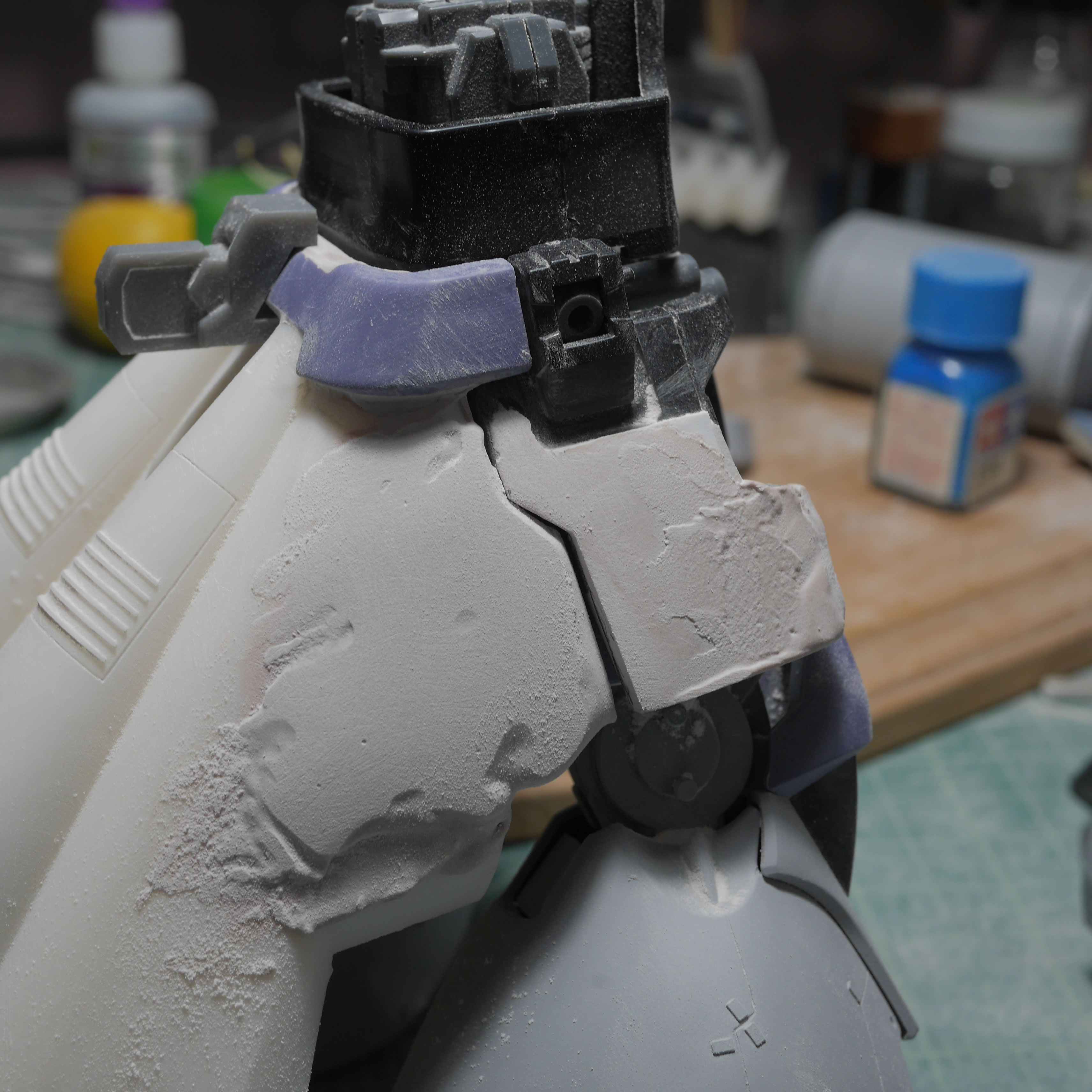
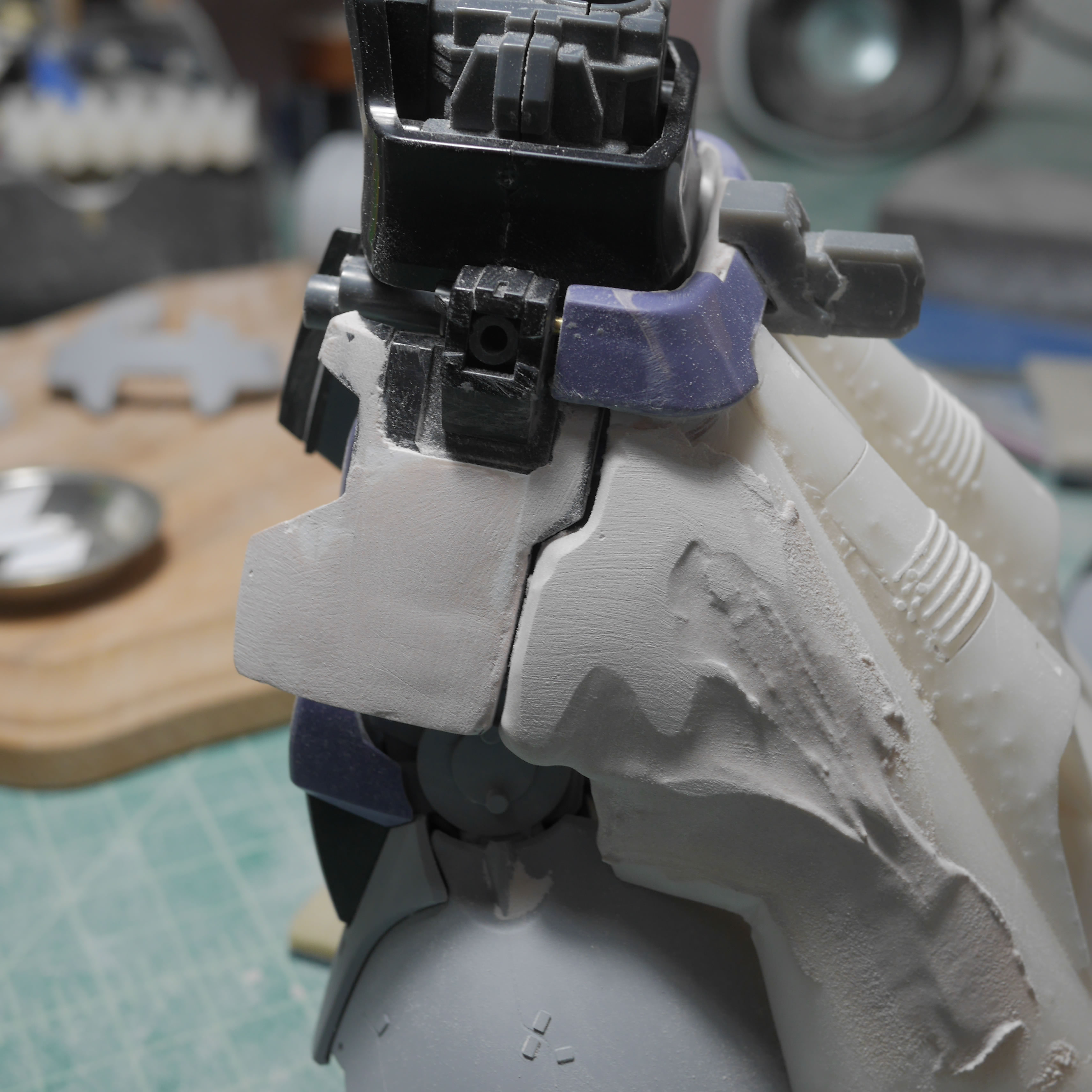
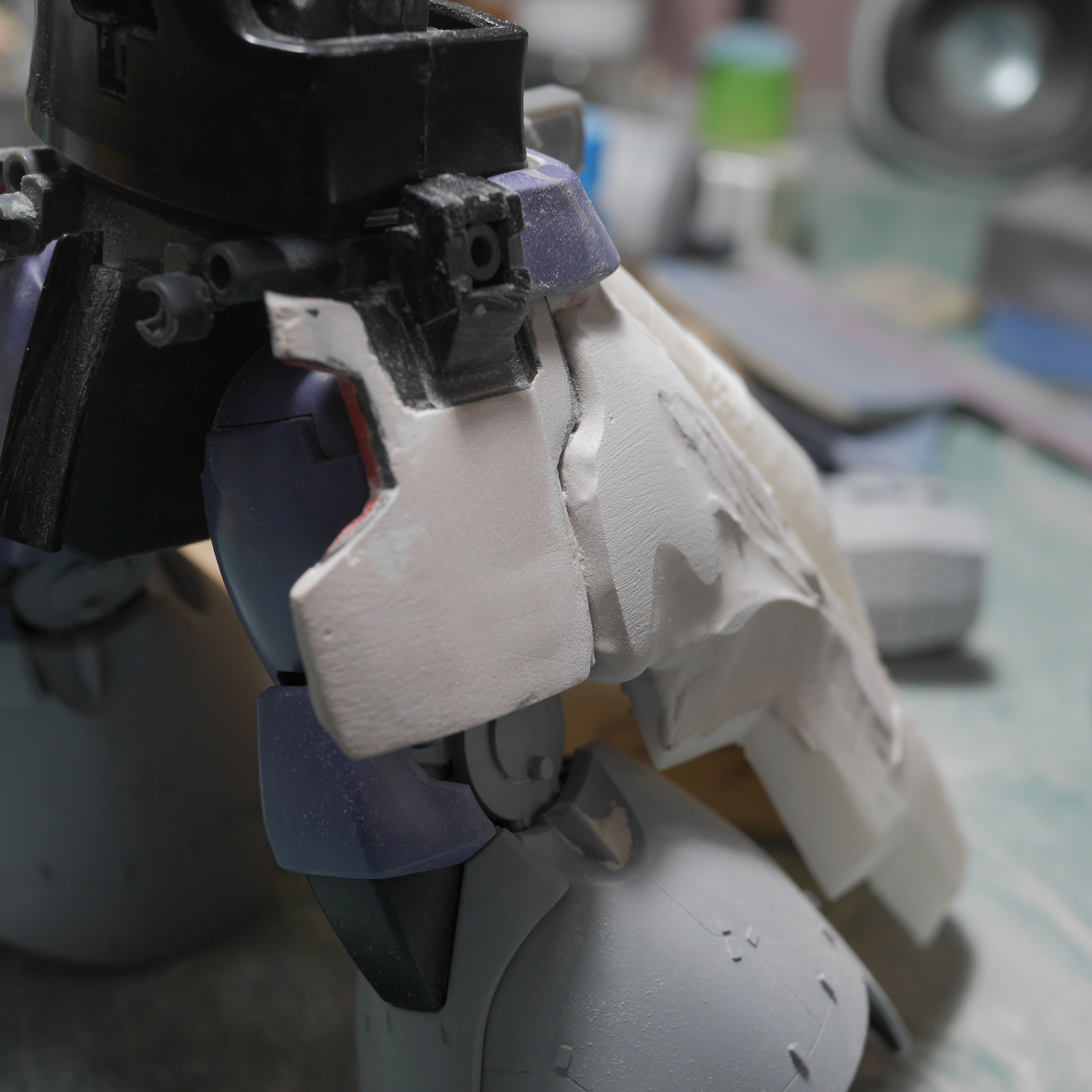
More fine tune sanding to get the basic shapes. The shoulders are also puttied over glued on plastic strip structures. The putty really needs something to grab. Think of this like pouring concrete without an internal structure.
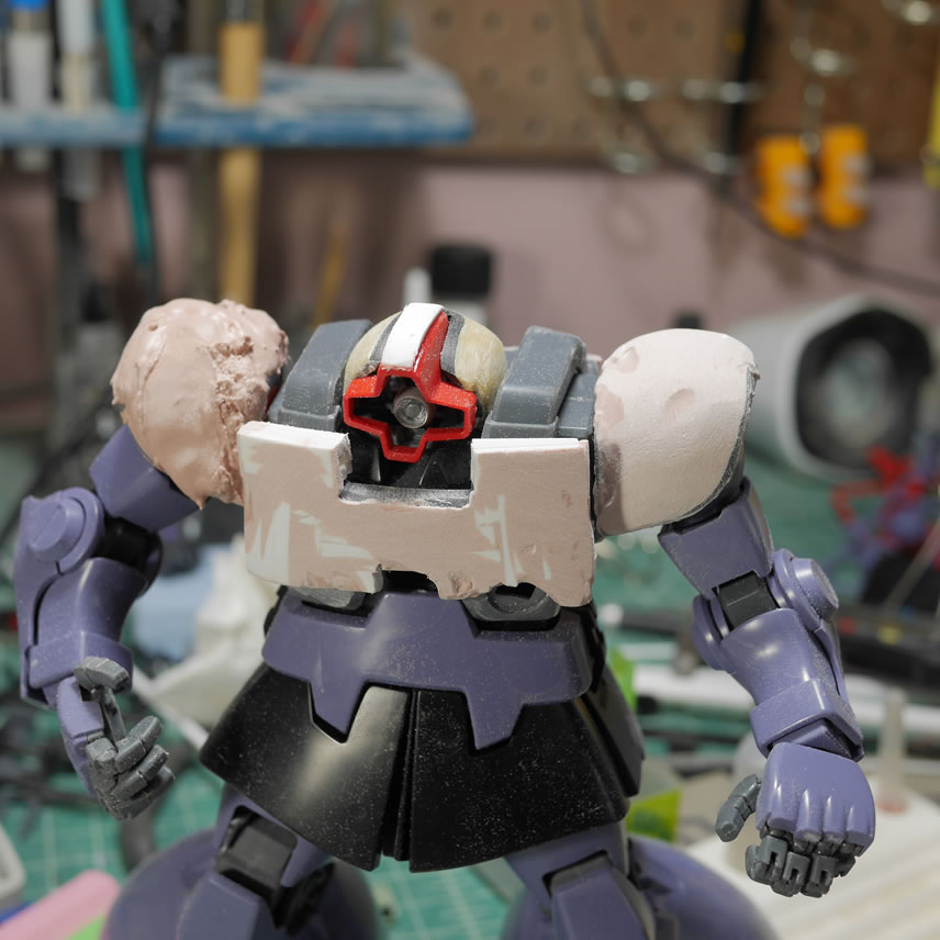
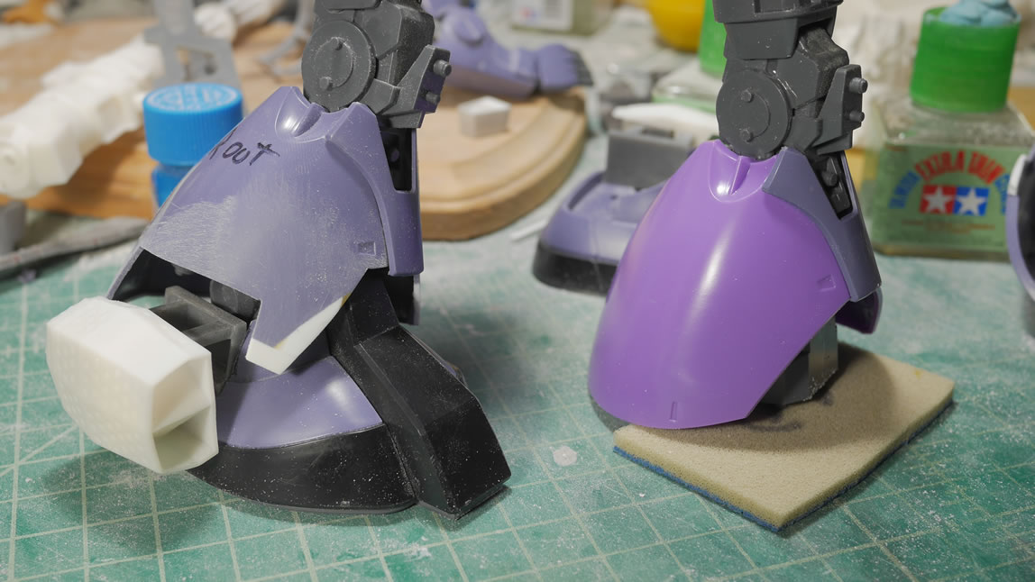
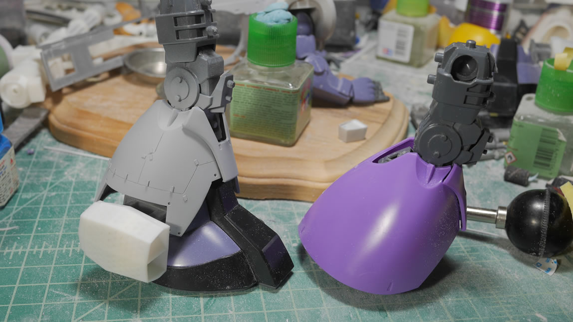
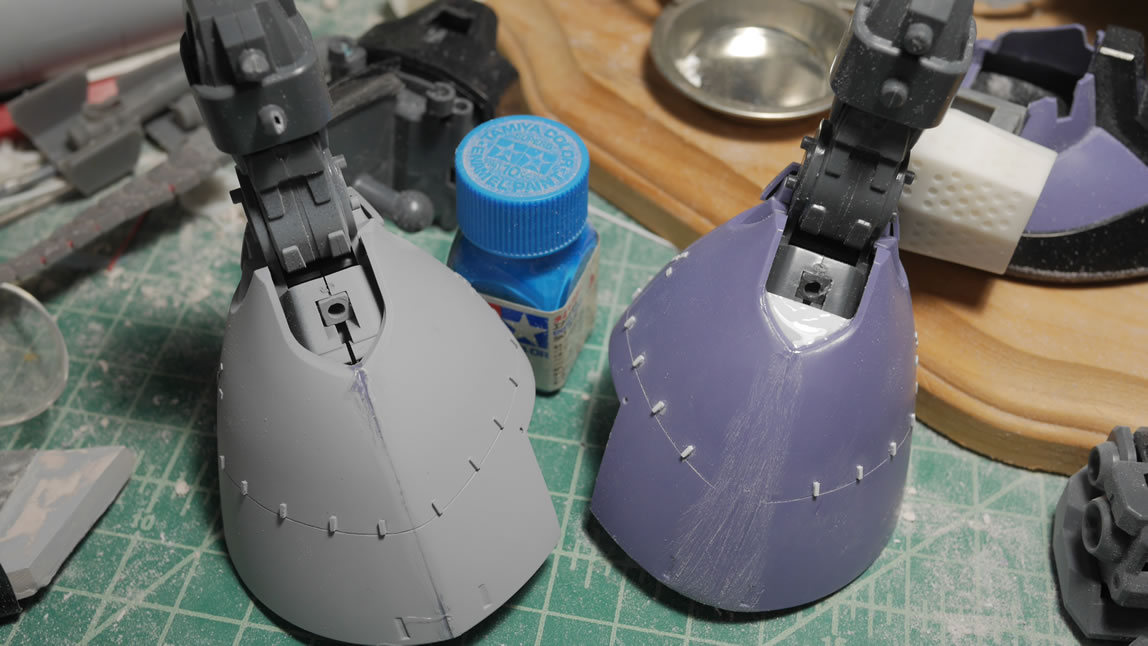
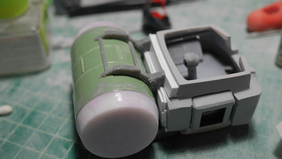
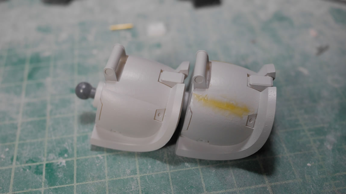
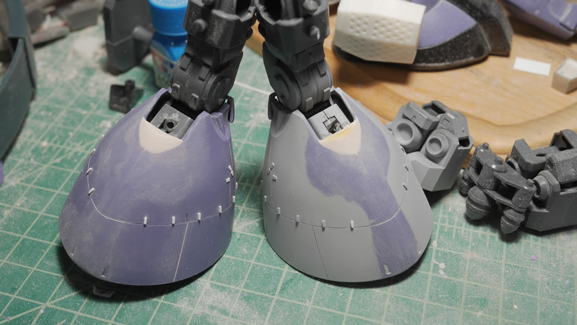
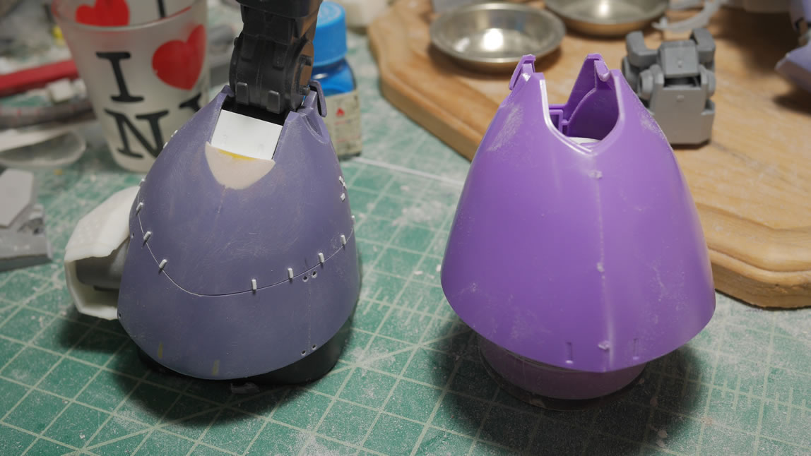
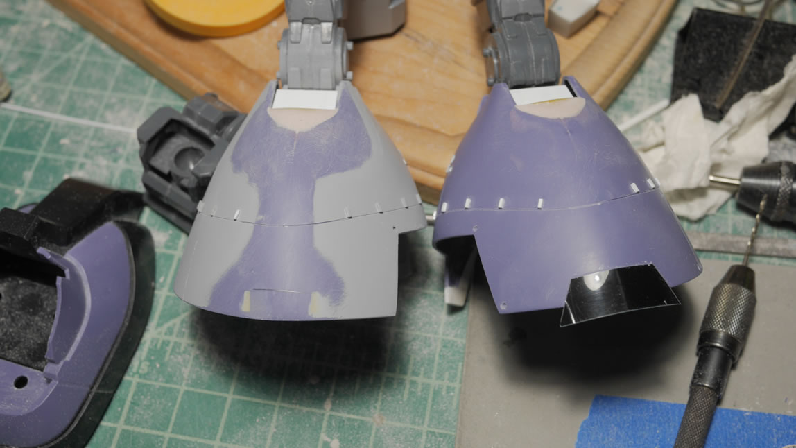
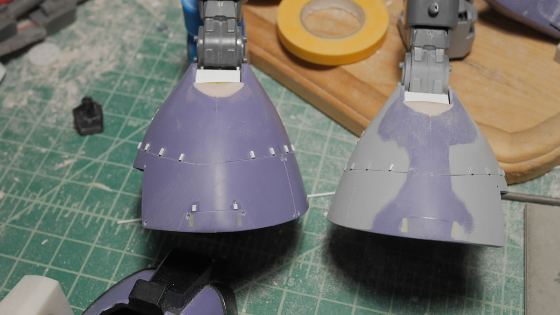
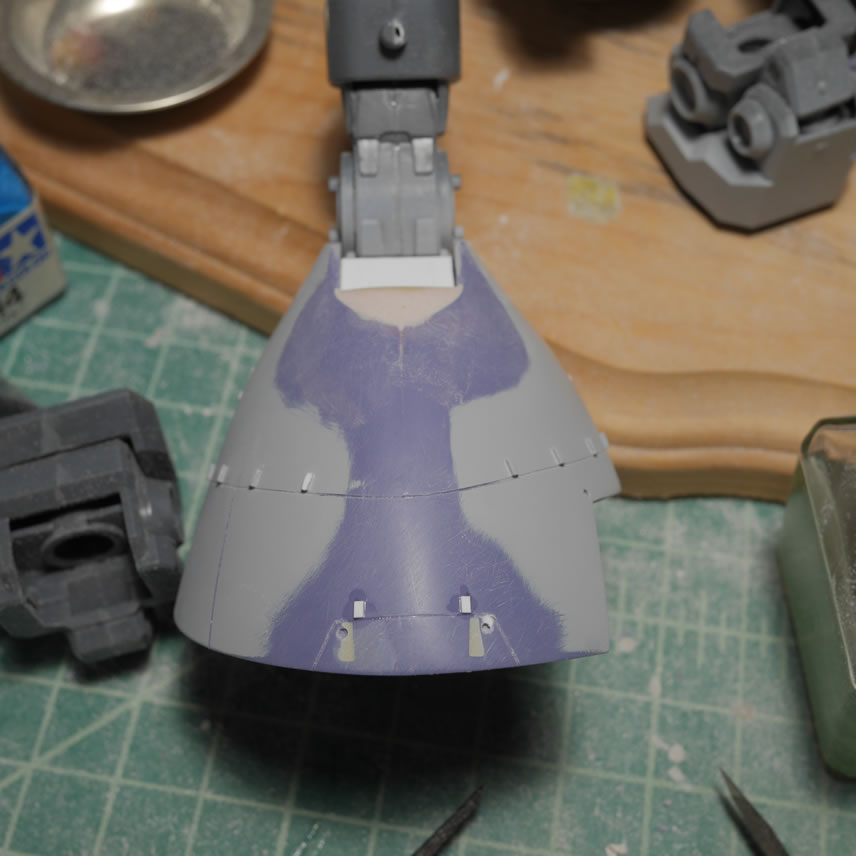
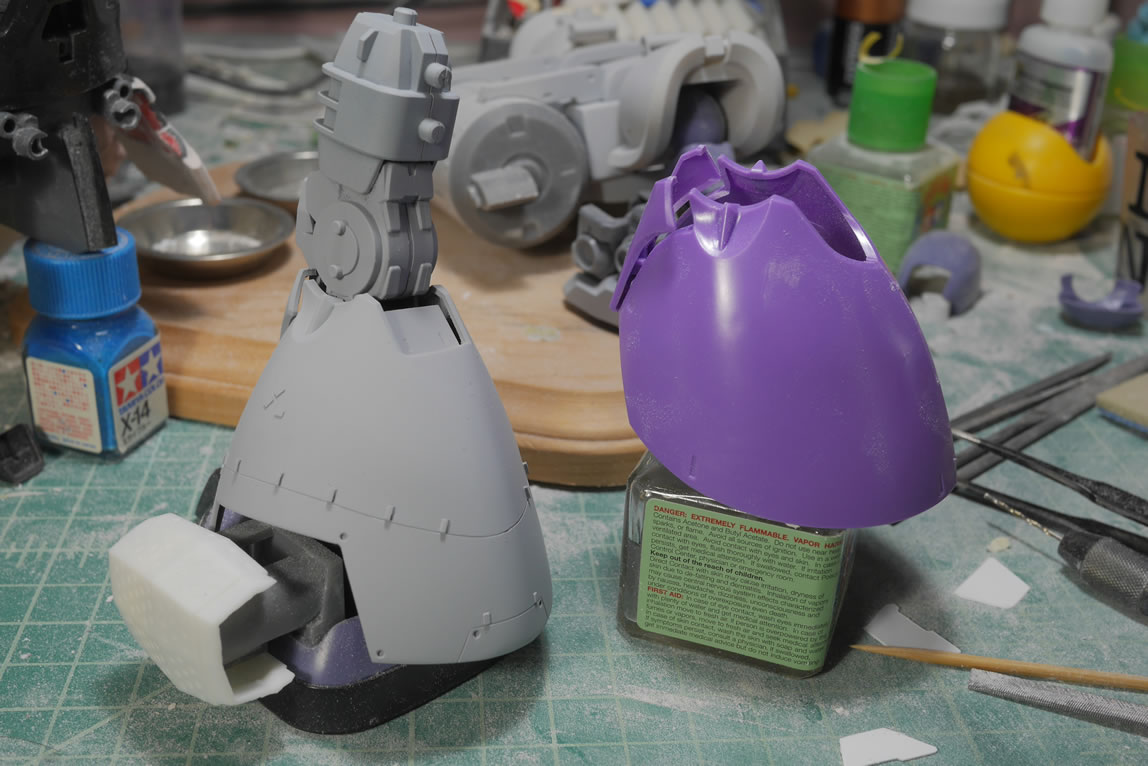
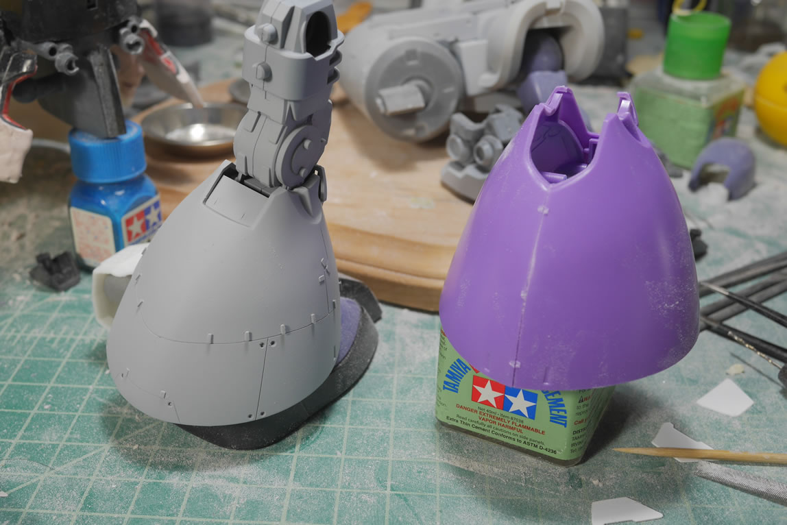
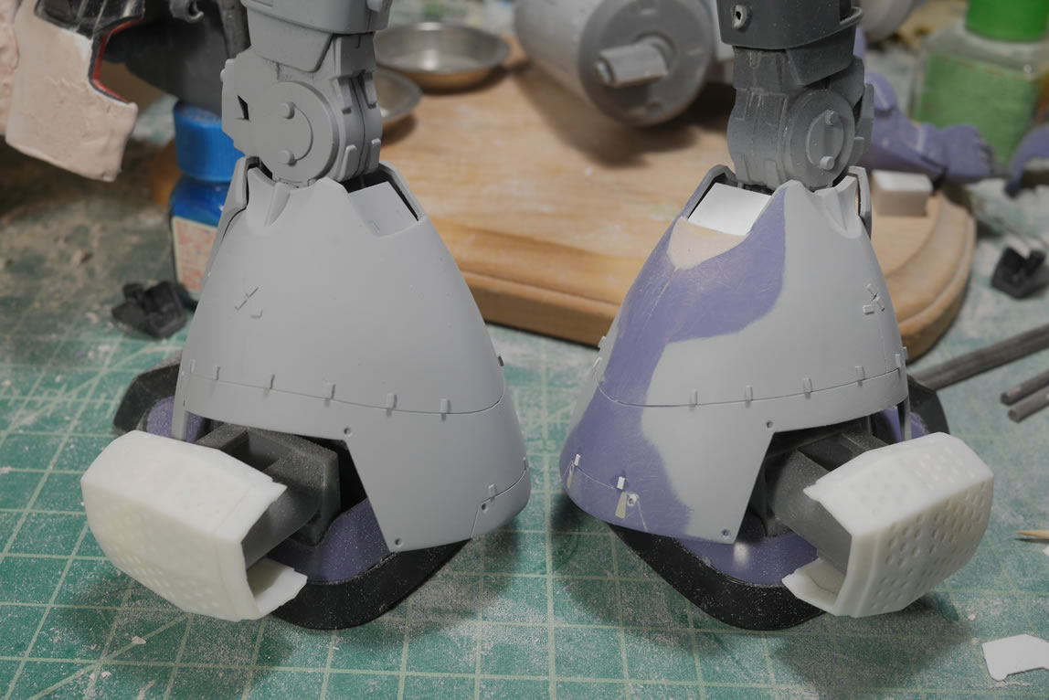
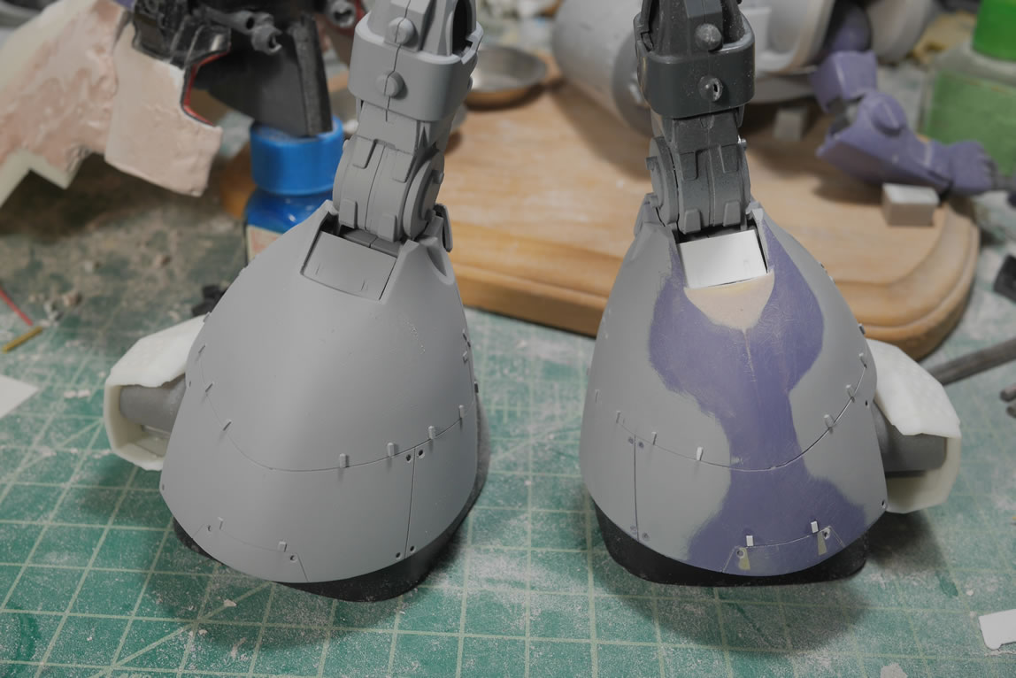
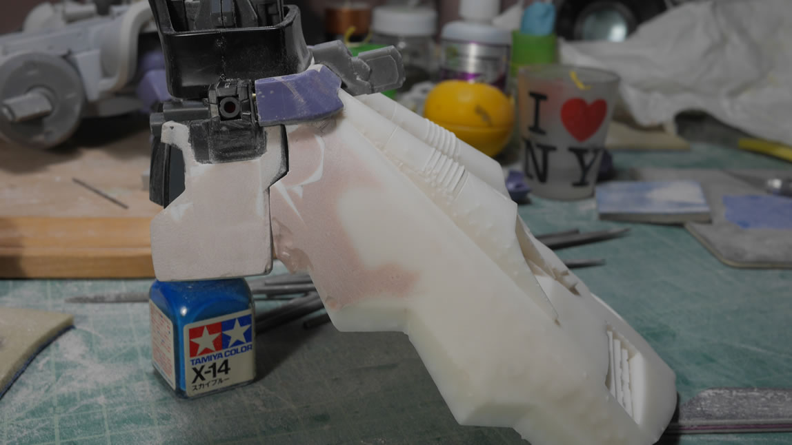
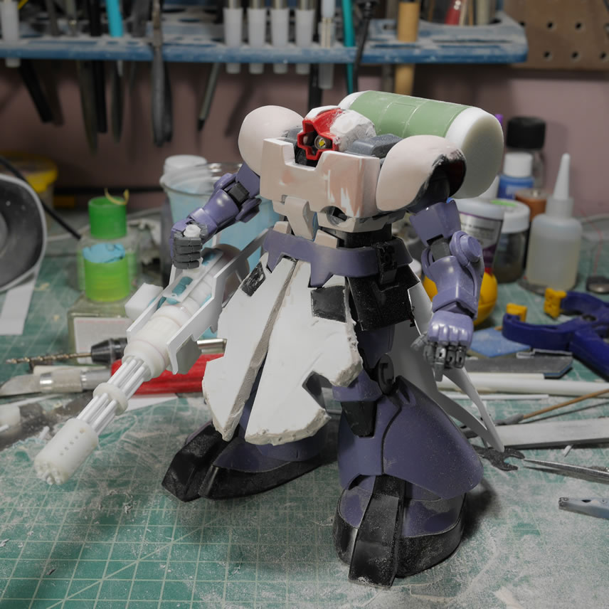
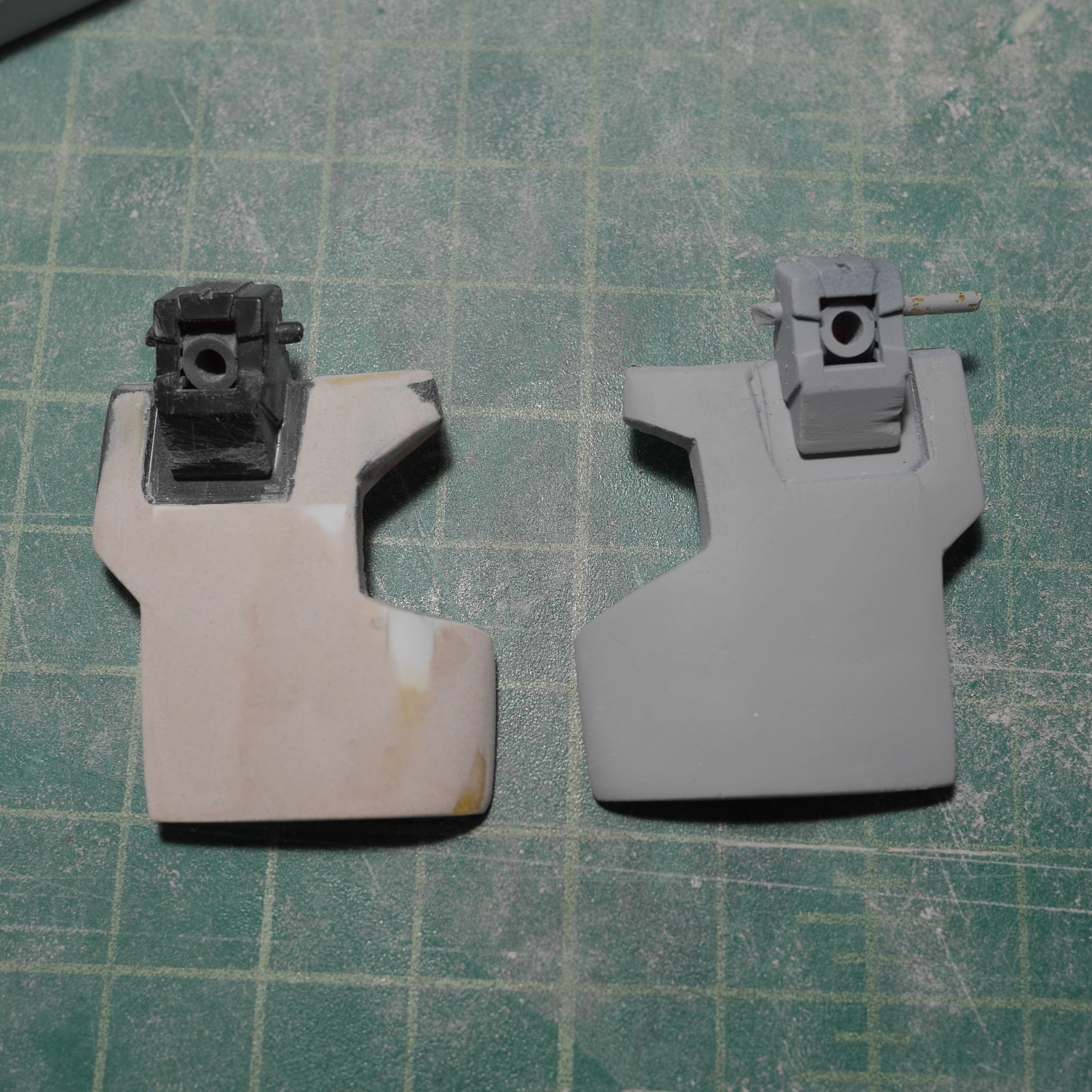
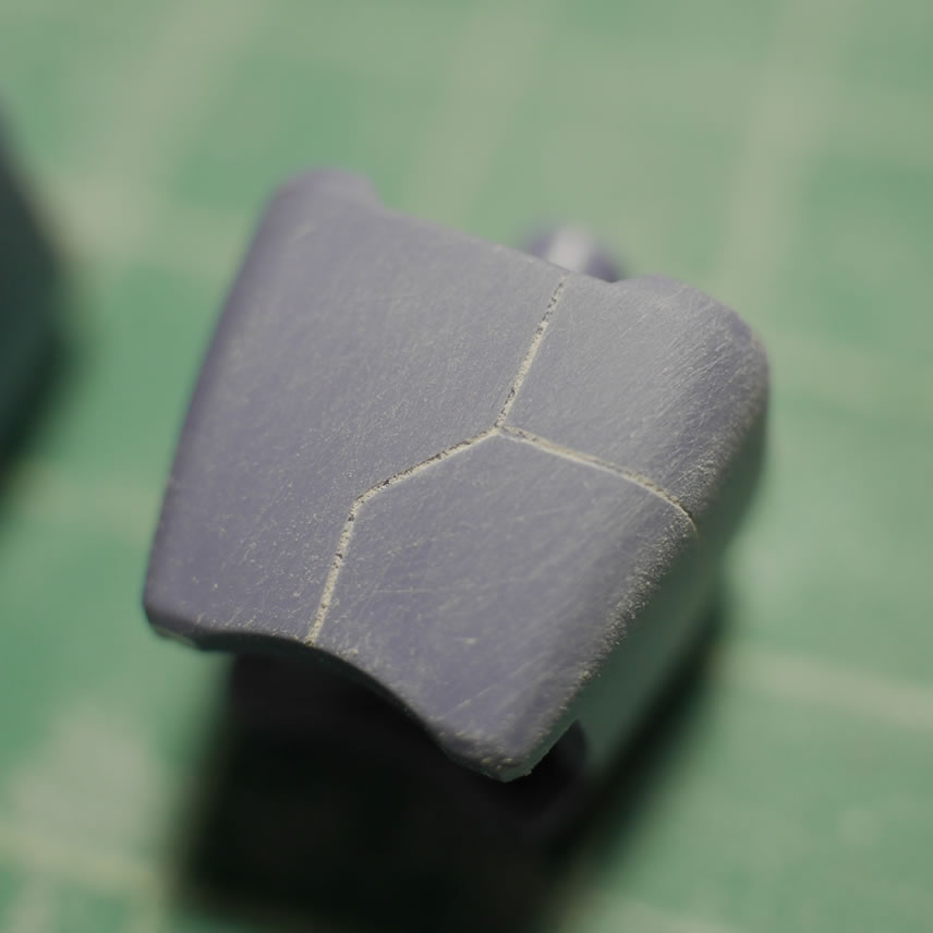
This is not a putty once and done type thing. Several cycles of putty, sand, putty sand and then more puttying and sanding will get to something that is close to the reference pictures. Here’s a comparison shot of the original part and the modified one; again, I have more than 1 MG Dom, so this will make direct comparisons relatively easy as I progress down this rabbit hole.
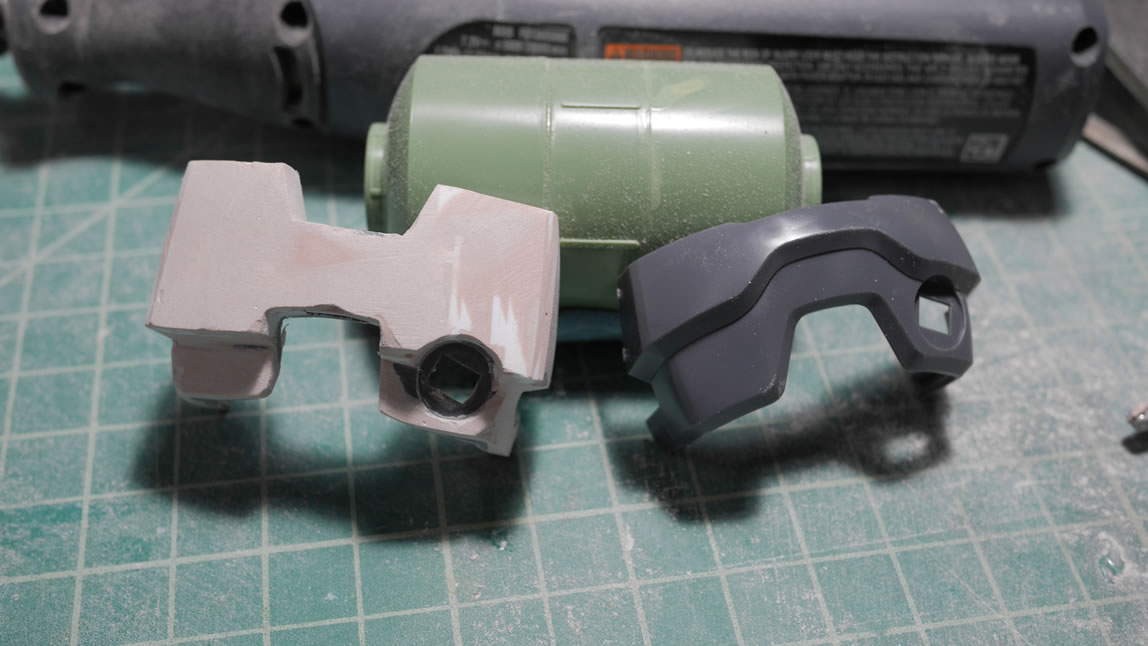
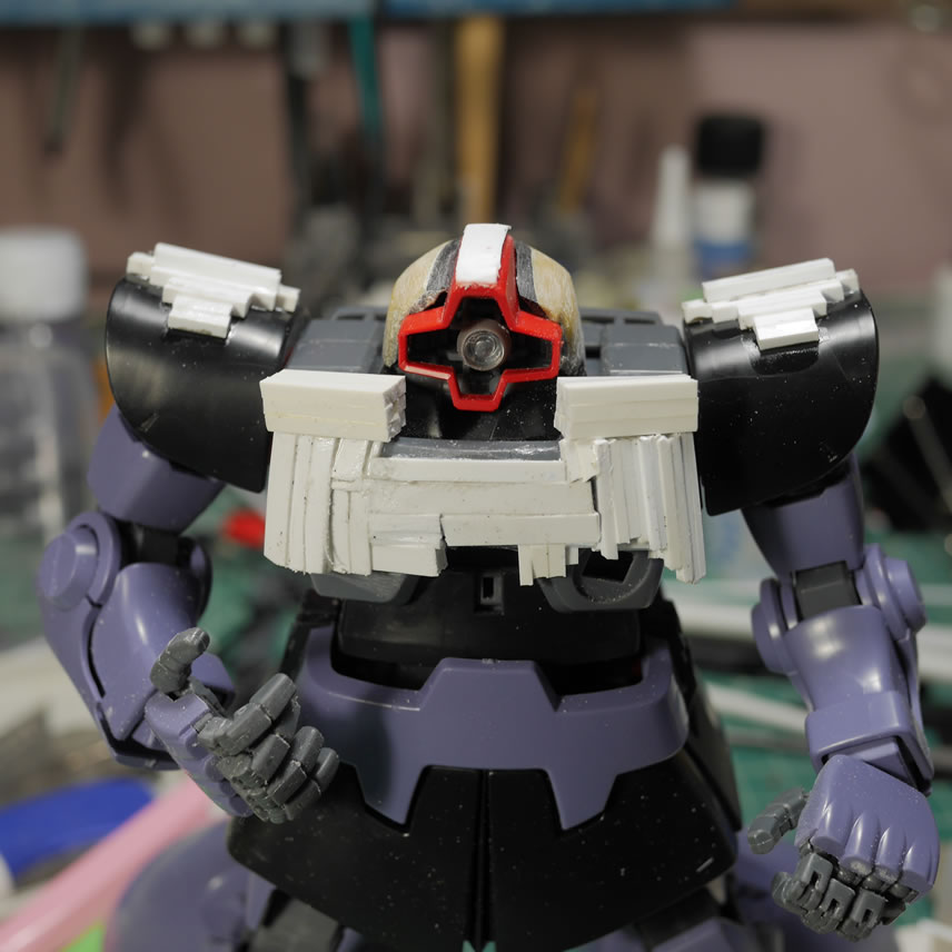
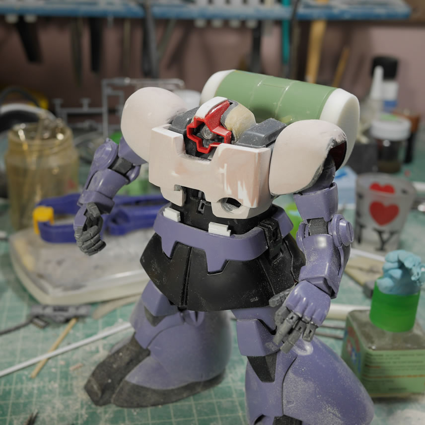
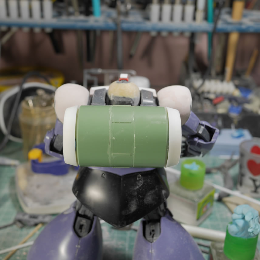
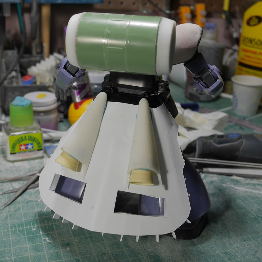
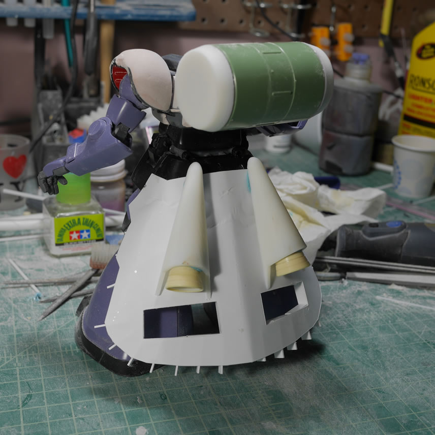
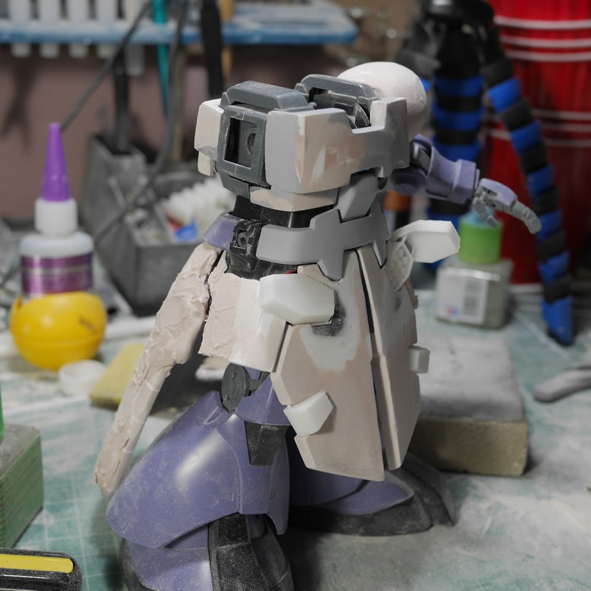
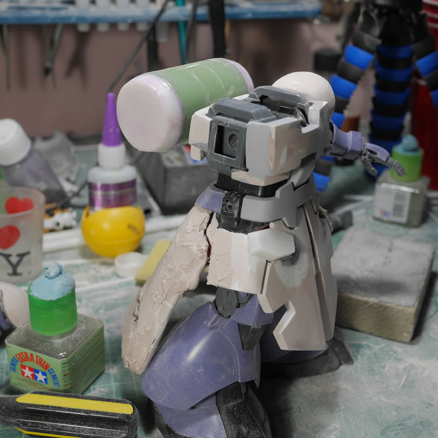
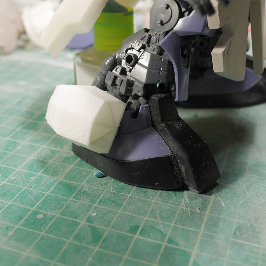
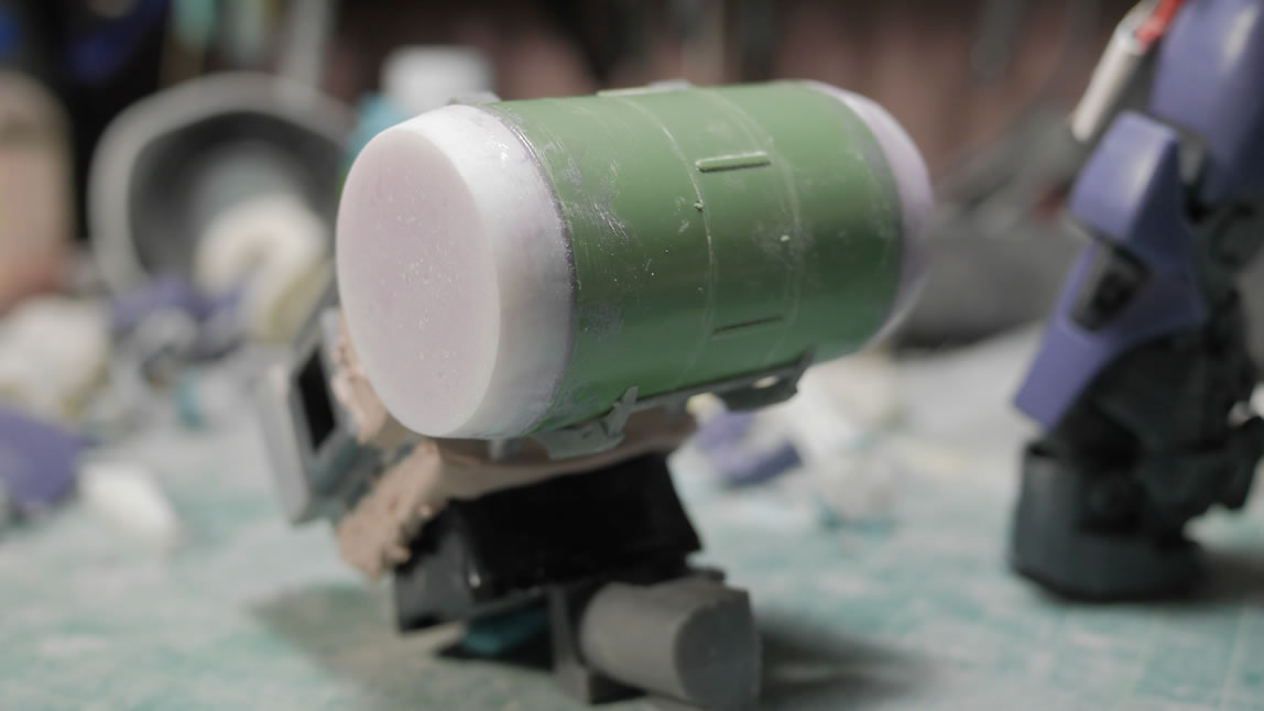
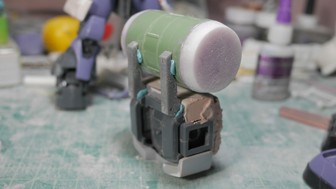
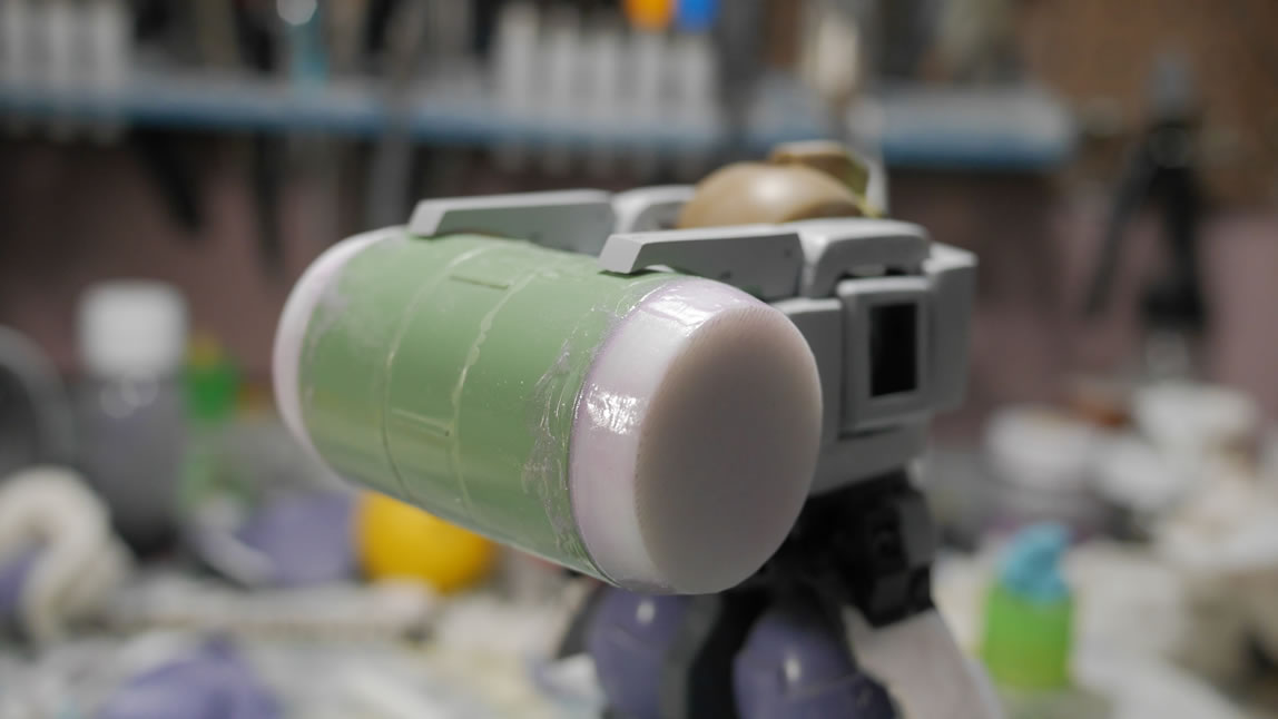
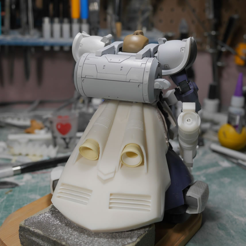
Notice that I added the giant ammo drum. The part is from the Kshatriya Repair that I bought for the Bear Guy project. The kit will not go to waste and I will continue to part it out to various projects.
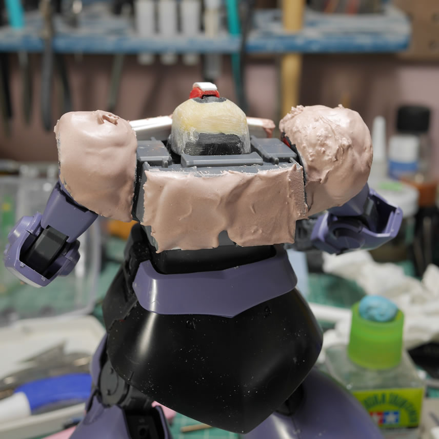
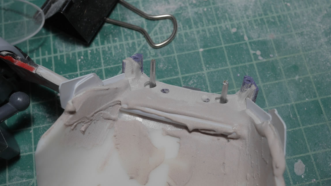
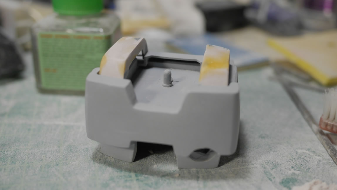
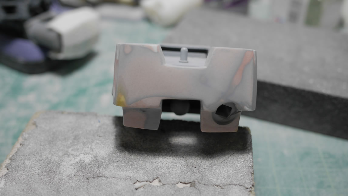
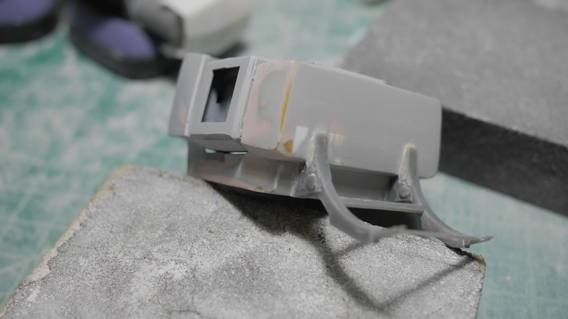
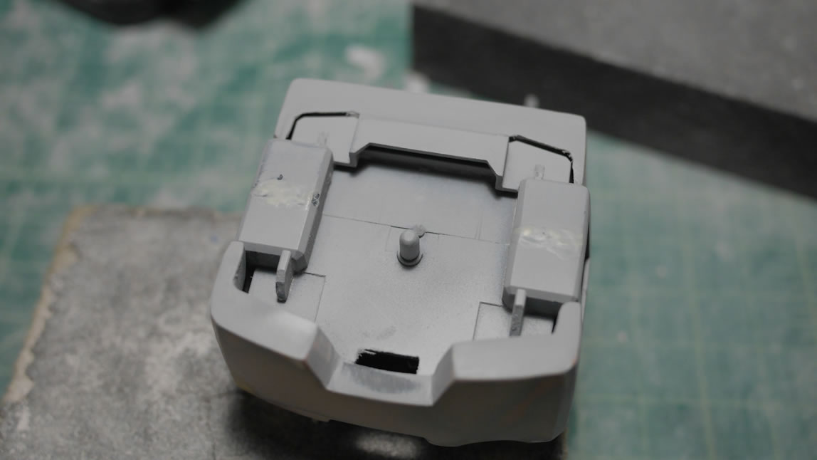
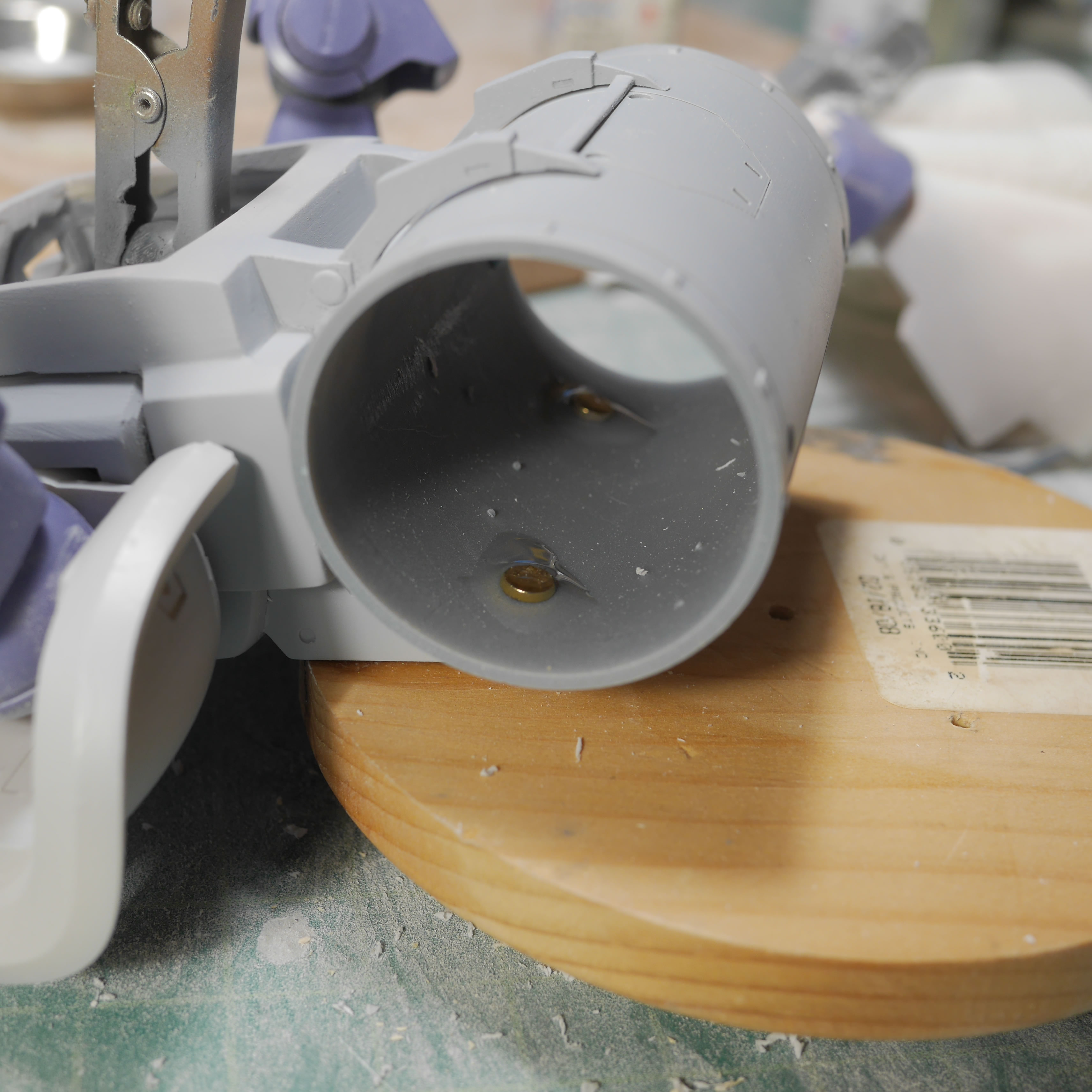
The rear of the Dom’s upper torso was also framed up and puttied. The original thruster molds and ports are filled as they are no longer any use. Once sanded, the polyester putty is sold enough that I can drill through it and punch an attachment hole. I added a piece from the MG Ball, another kit I grabbed for the Bear Guy project and added an attachment point for the drum. This area of the kit requires some guess work as I couldn’t see completely in where the drum attaches to the backpack. There are 4 attachment points from the upper chest and lower back to the drum, but I just guessed at a center attachment point.
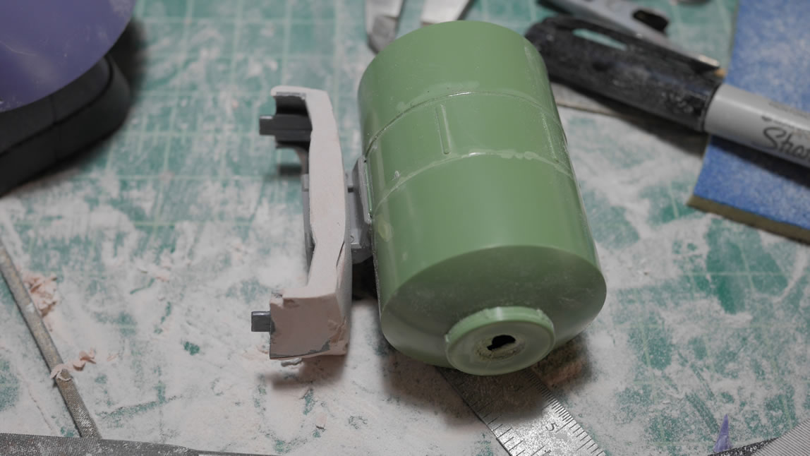
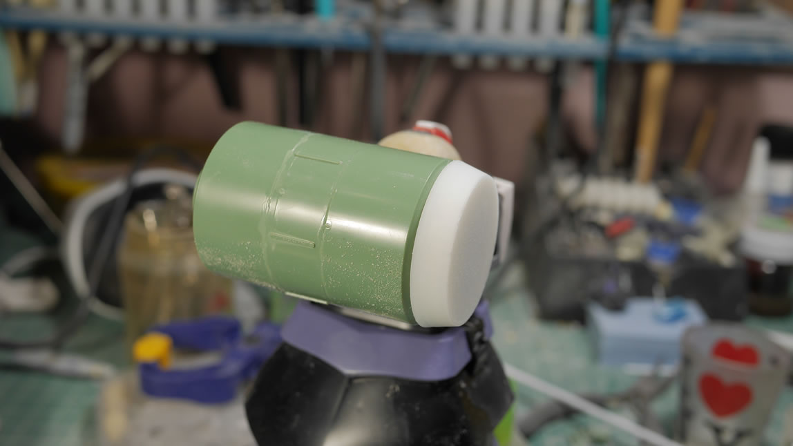
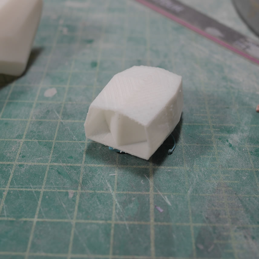
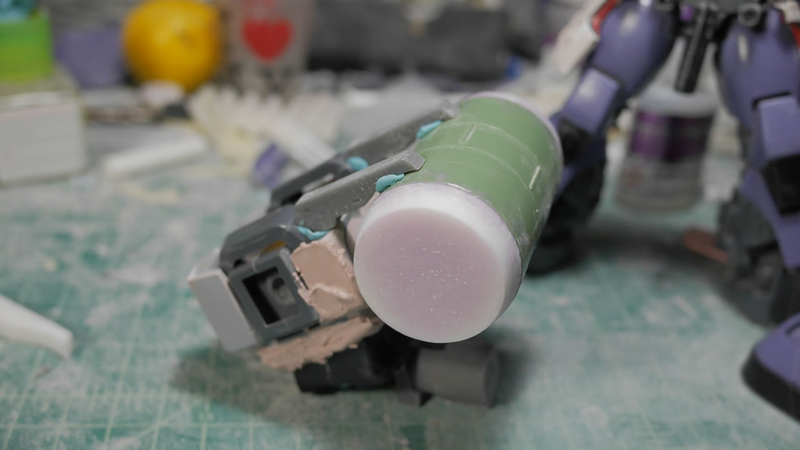
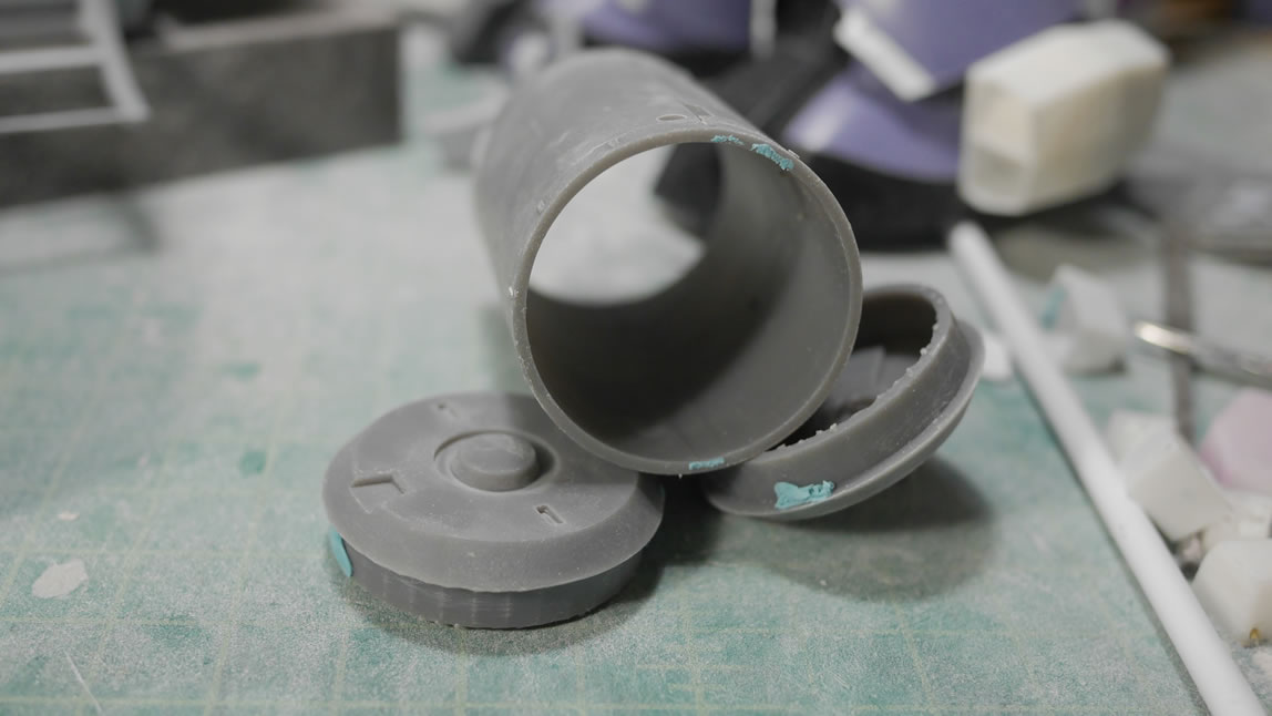
As said earlier, the main drum is built from three round parts off the Kshatriya. I then designed some quick end caps to the drums to finish off the basic look and feel for the ammo pack.


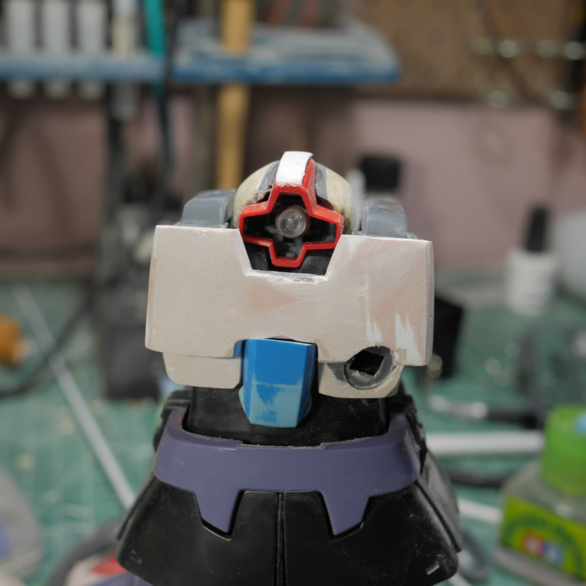
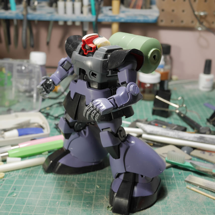
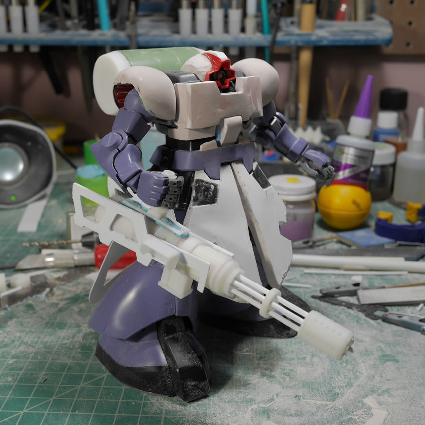
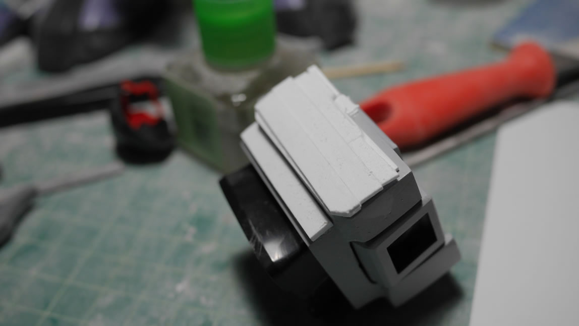
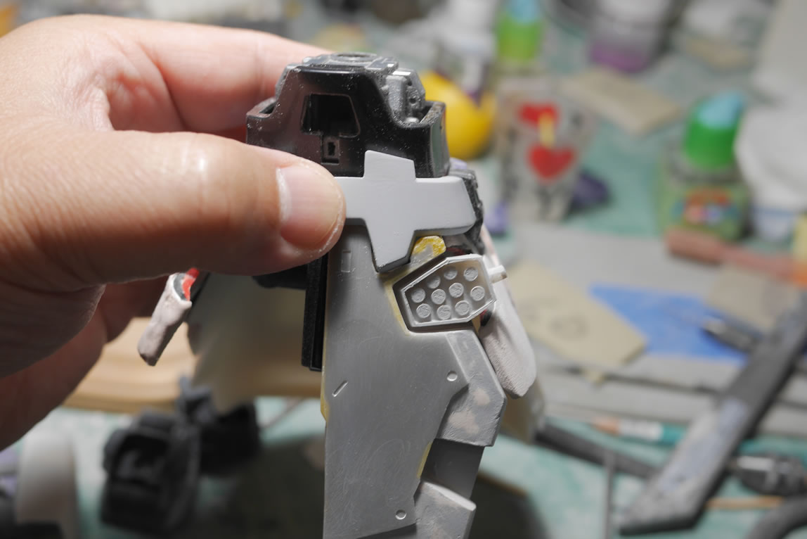
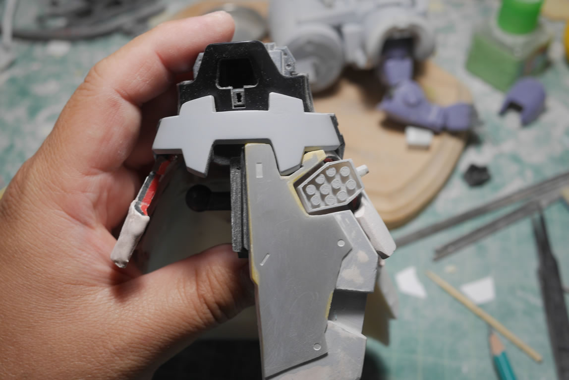
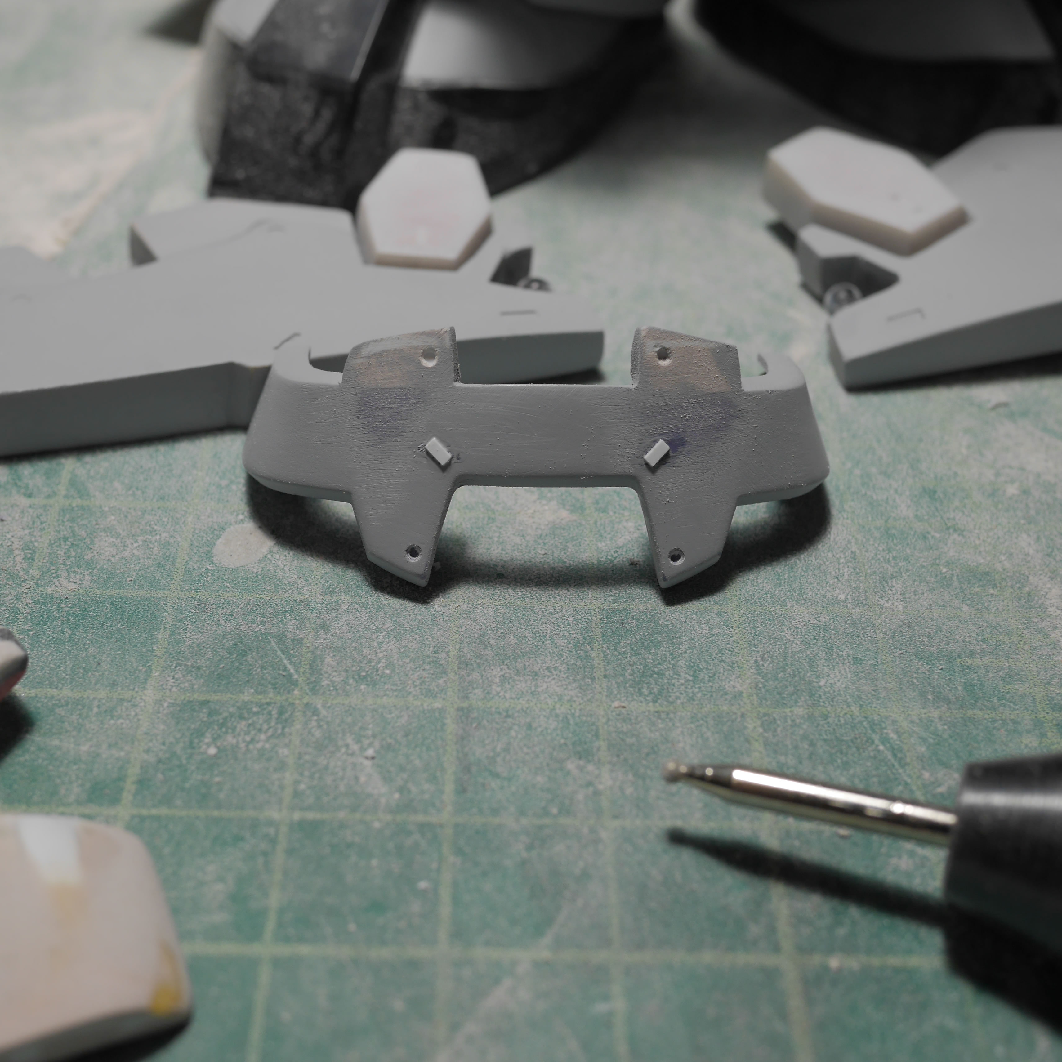
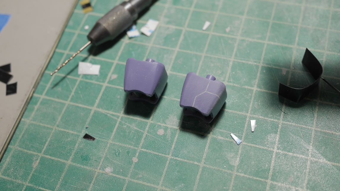
A quick test fit with the parts so far. The head is starting to get some sanding but I will definitely need to come back and add more putty there. But things are progressing. The “belt” if you will has been modified to remove the raise middle section that is more inline with the Dom Trop’s belt style.
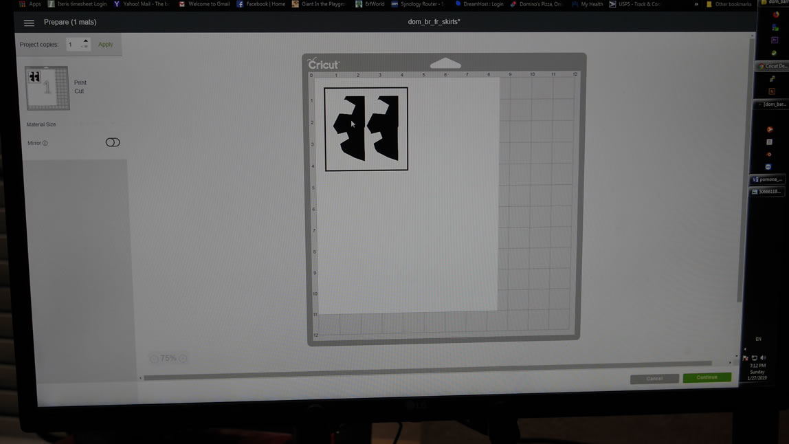
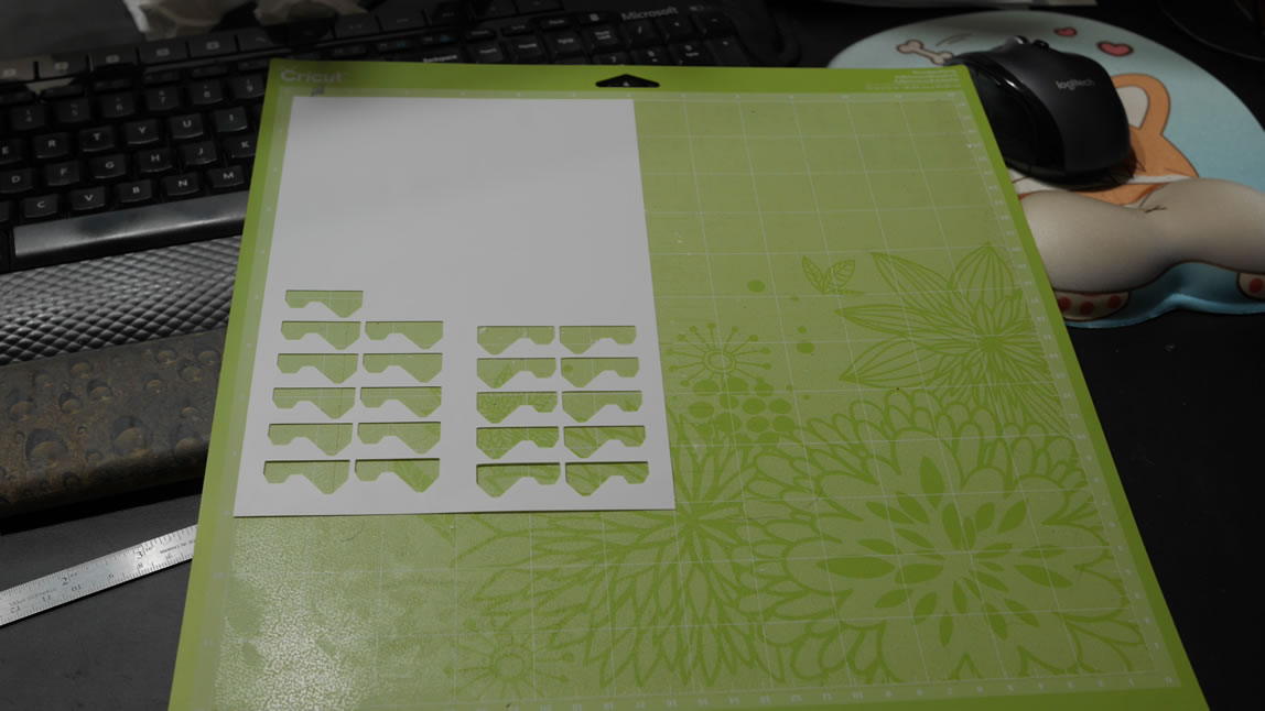
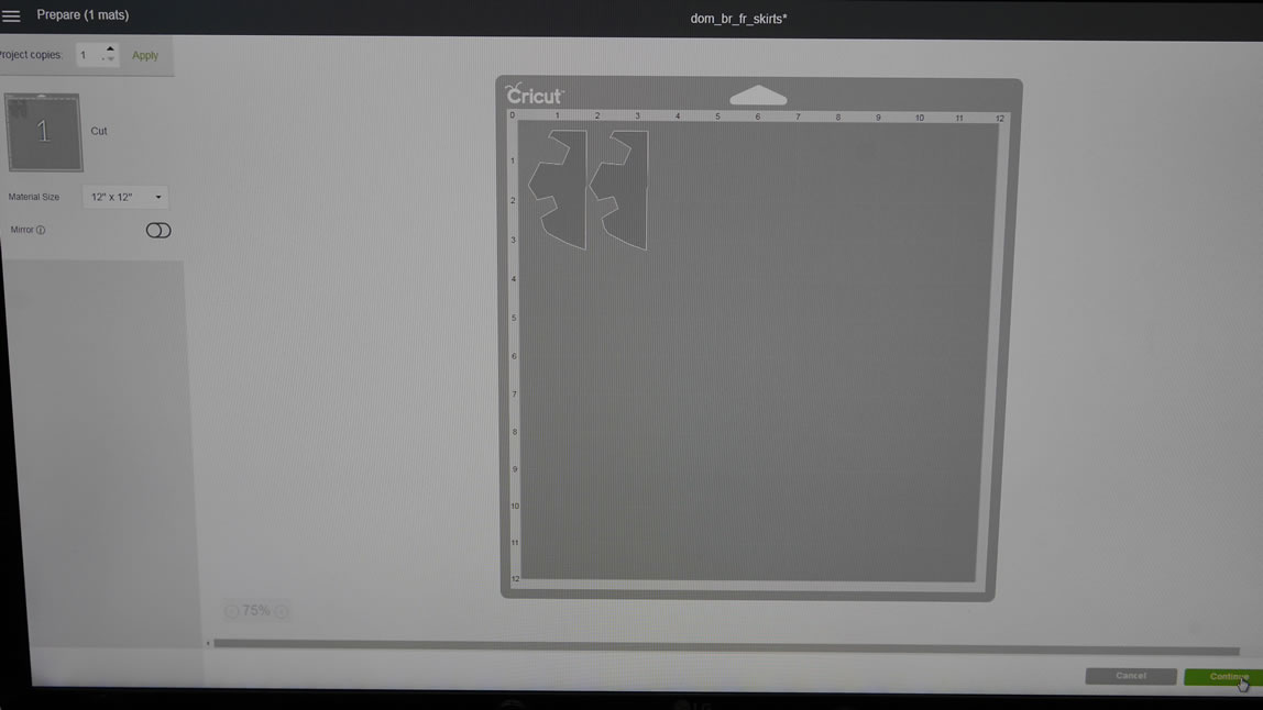
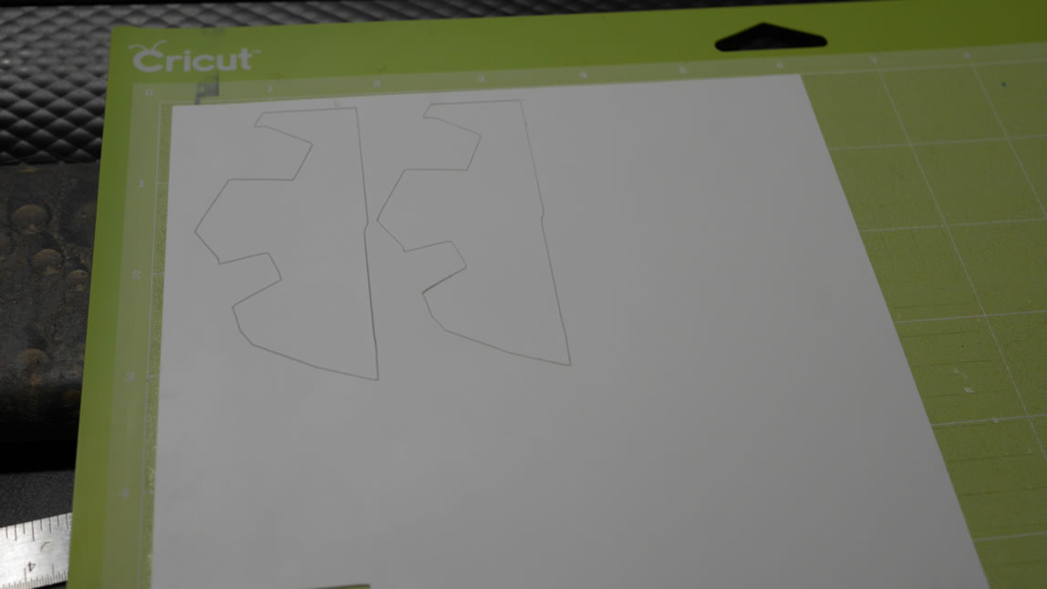
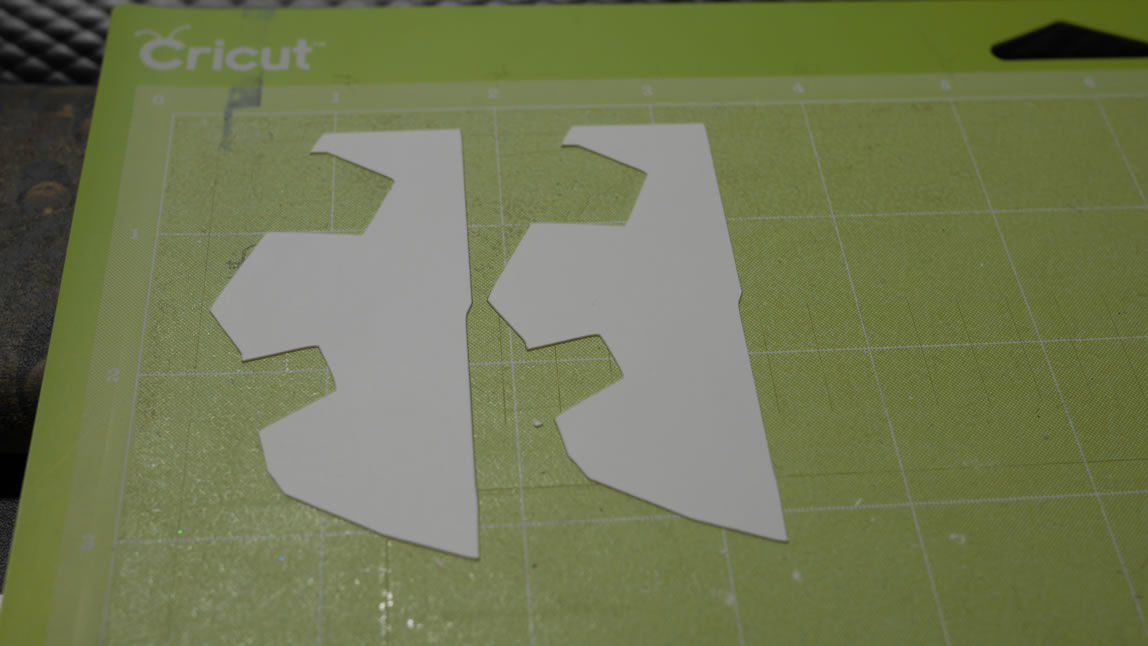
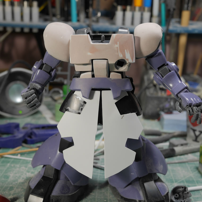
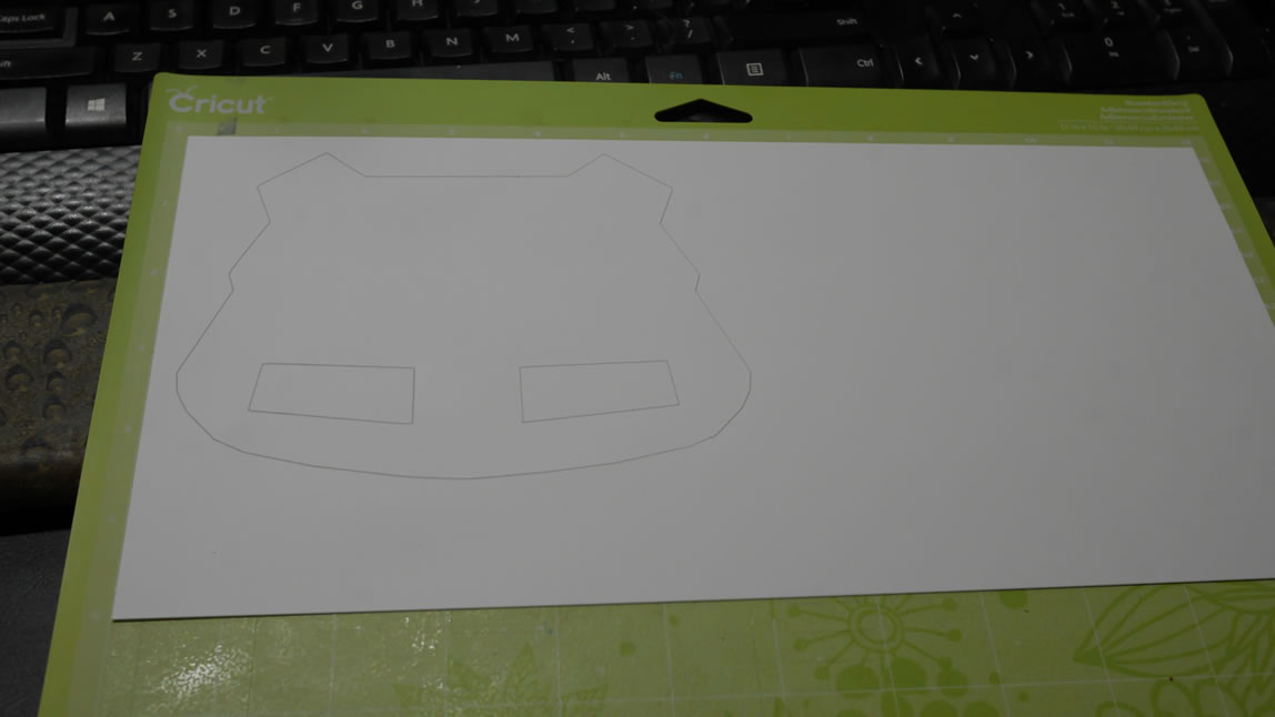
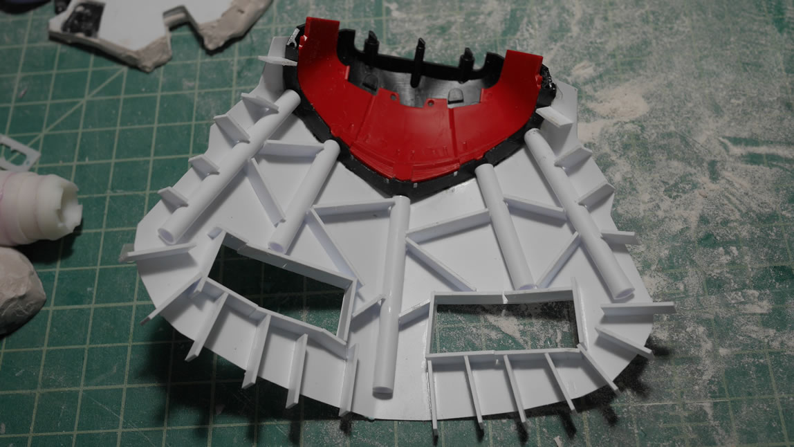
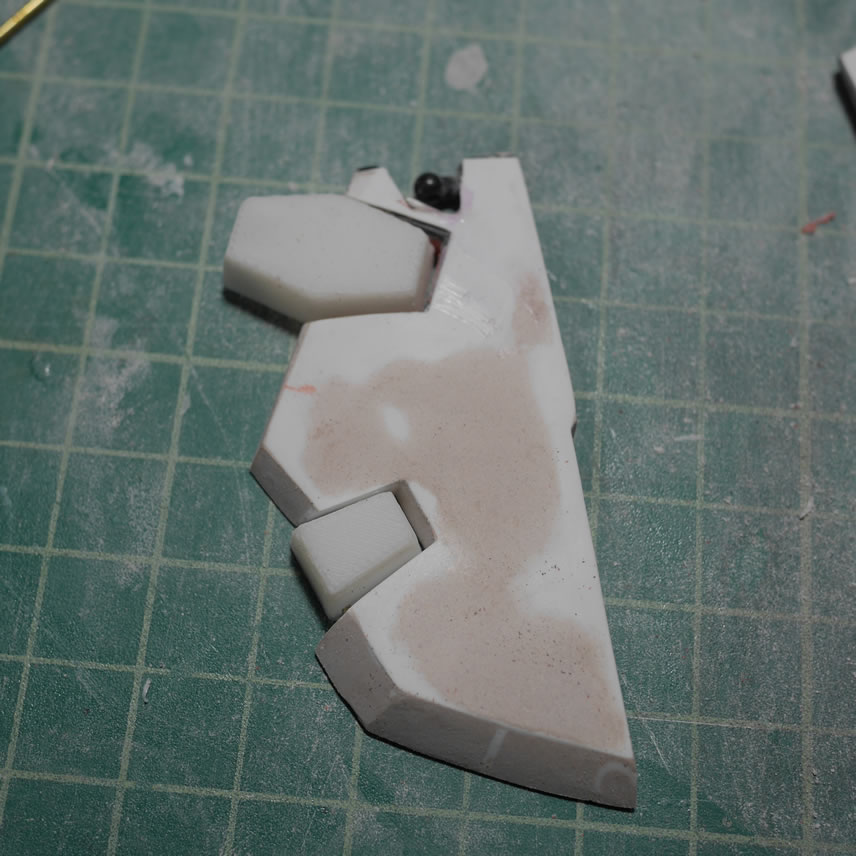
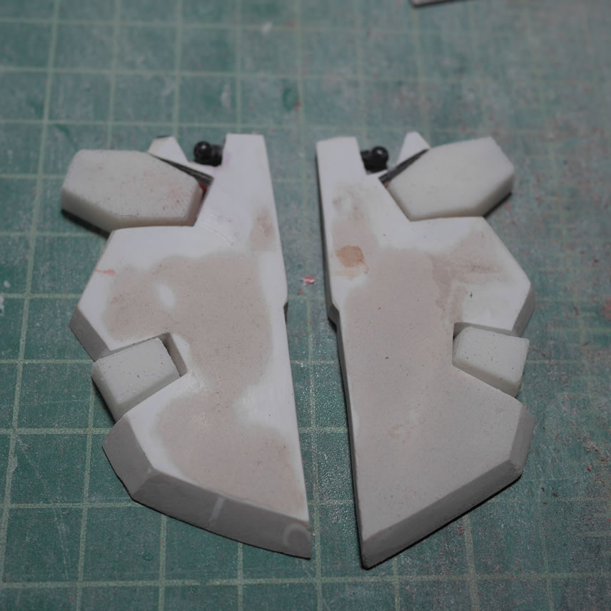
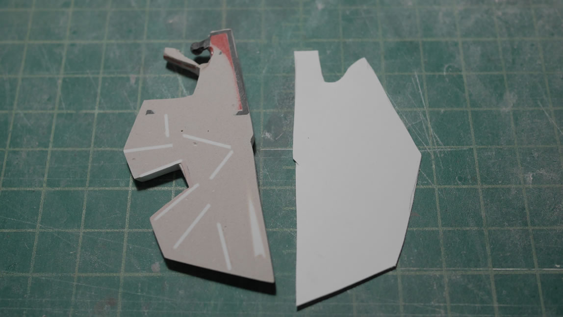
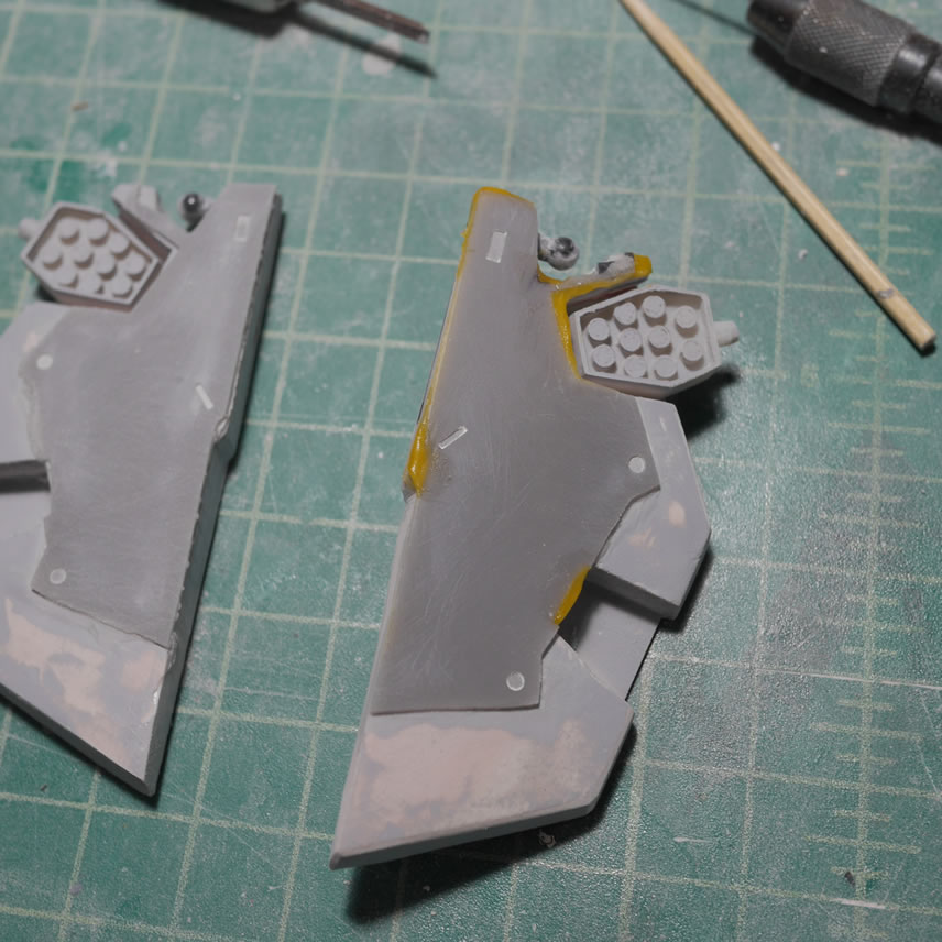
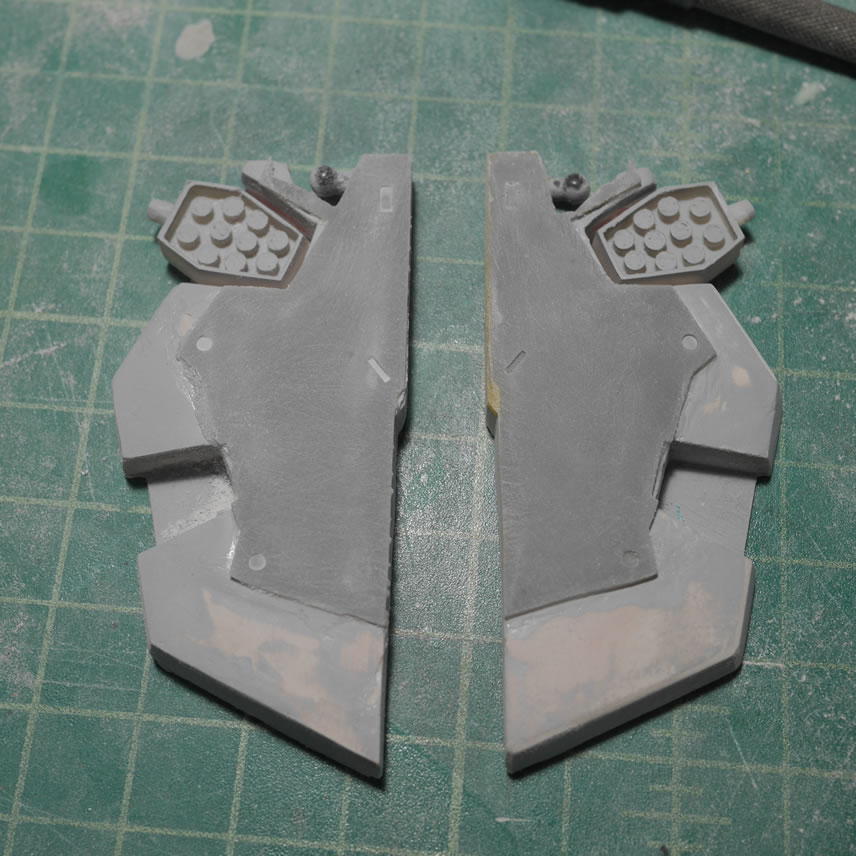
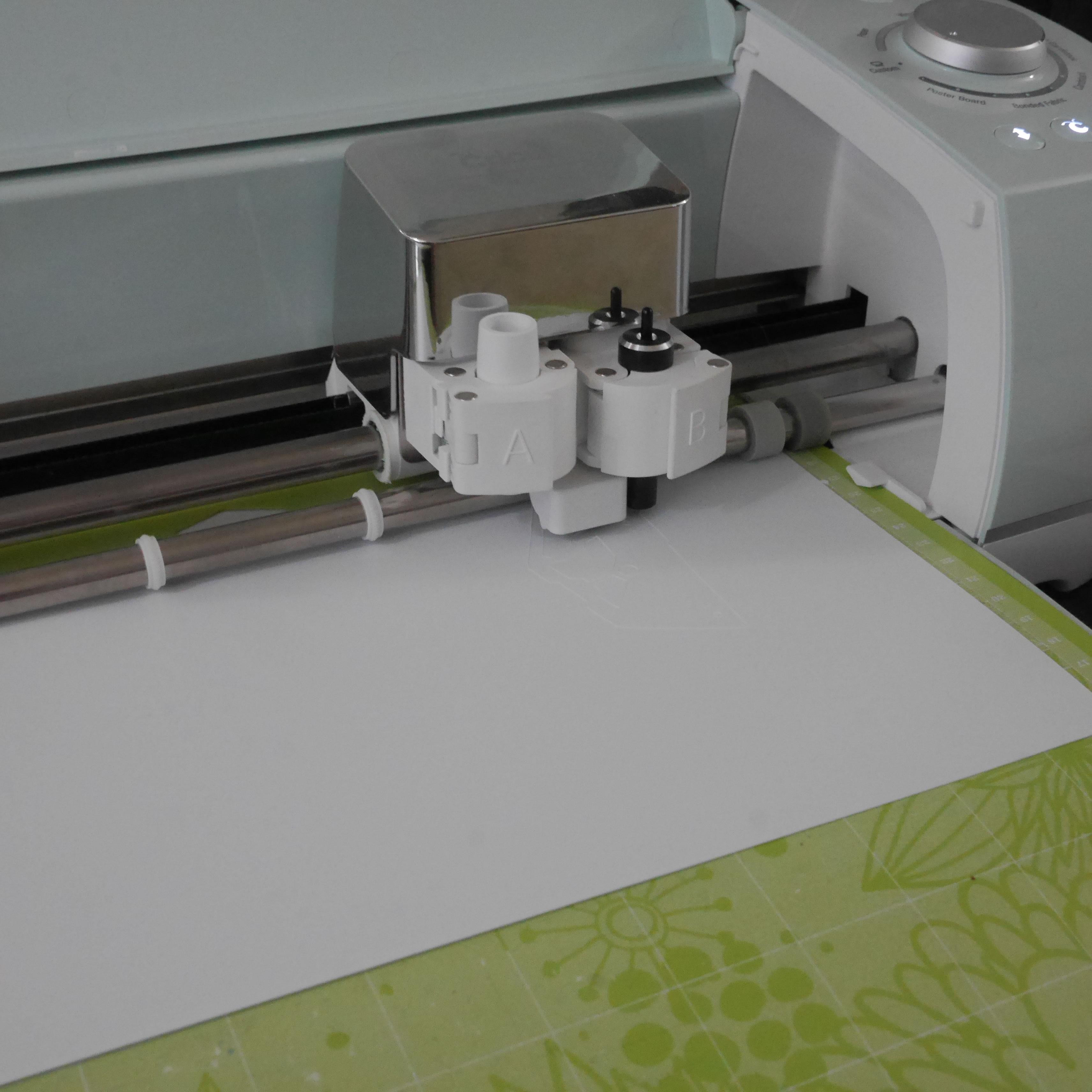
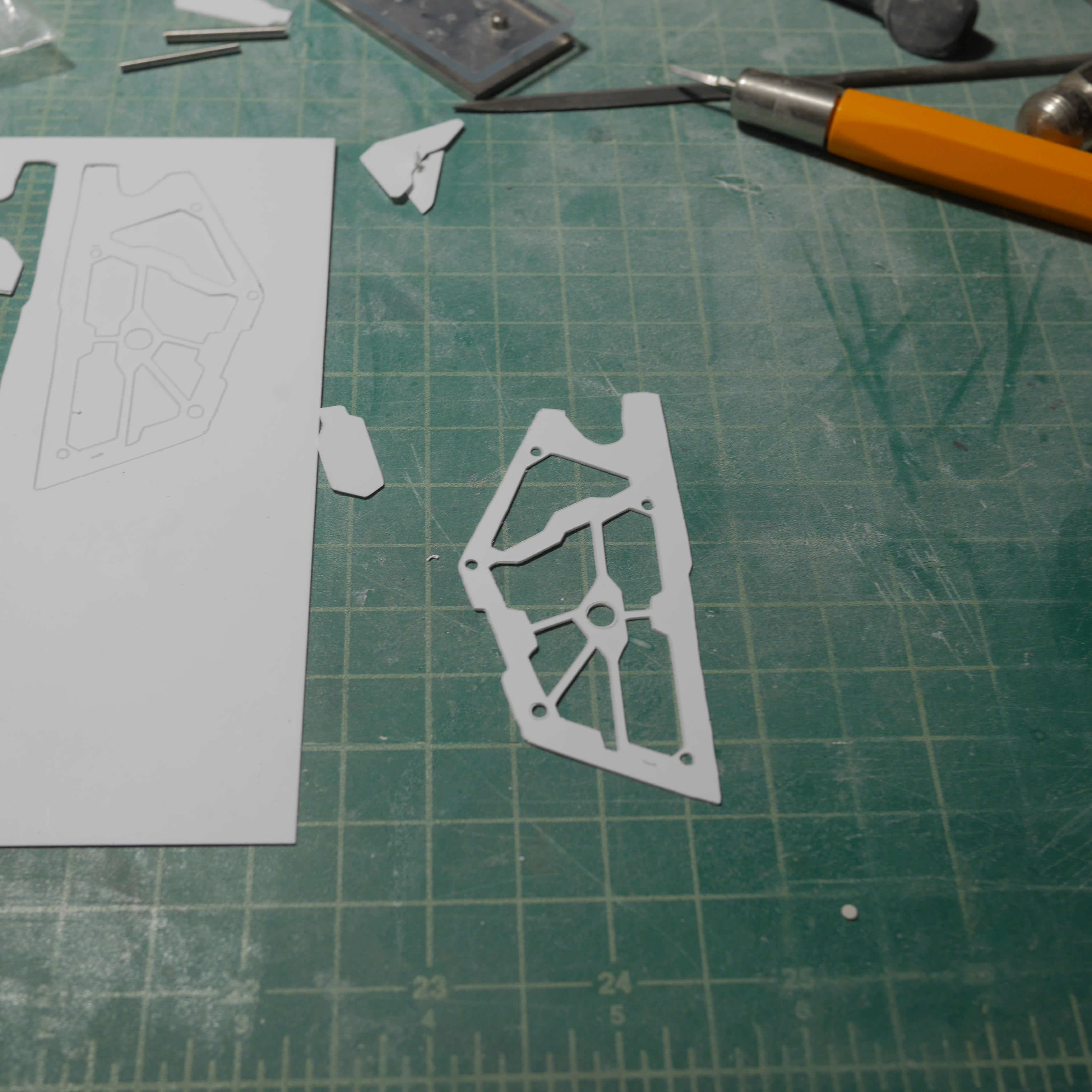
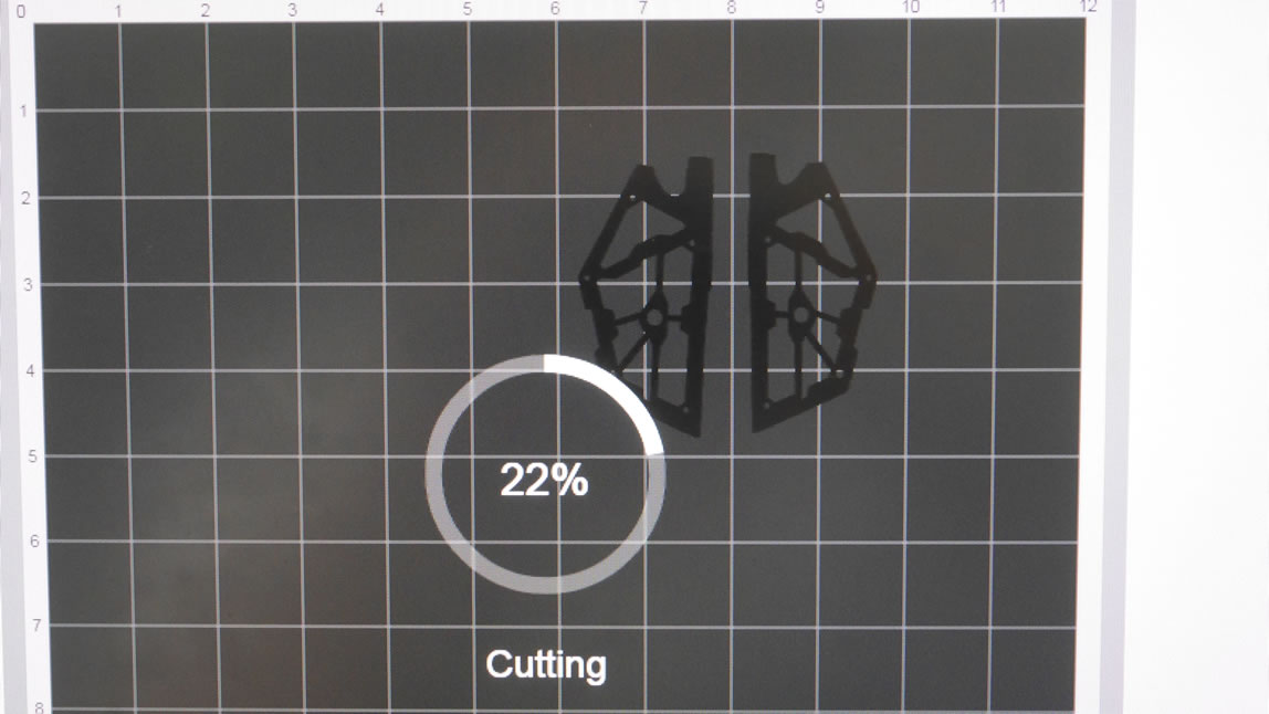
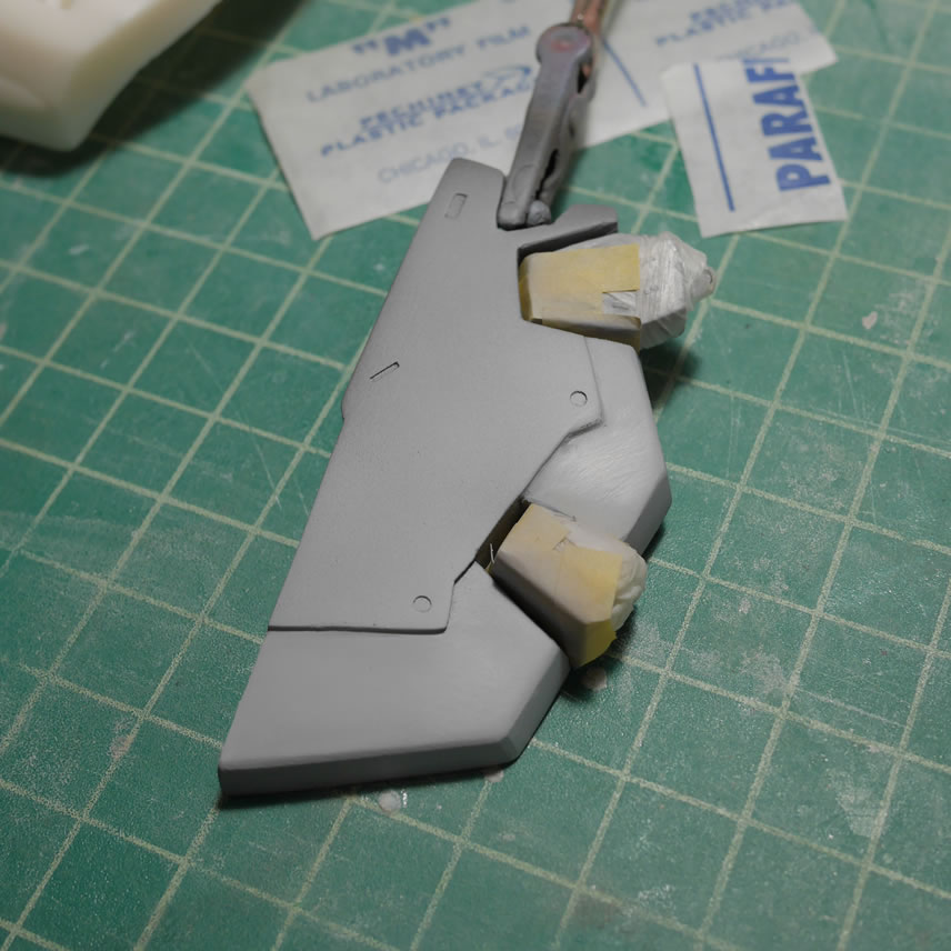
Next up, the front skirts. Using the reference screen shots, I drew out the rough shape of one of the front skirts and ported it to the cricut design software to cut the part out of plastic sheet. The cutter with the deep cut knife can cut fairly cleaning through .4mm thick styrene. I’m cutting through .2mm styrene for the front skirt so I made 4 copies. I glued two copies together to get a .4mm front skirt piece.
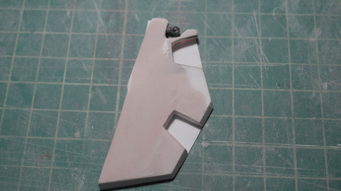
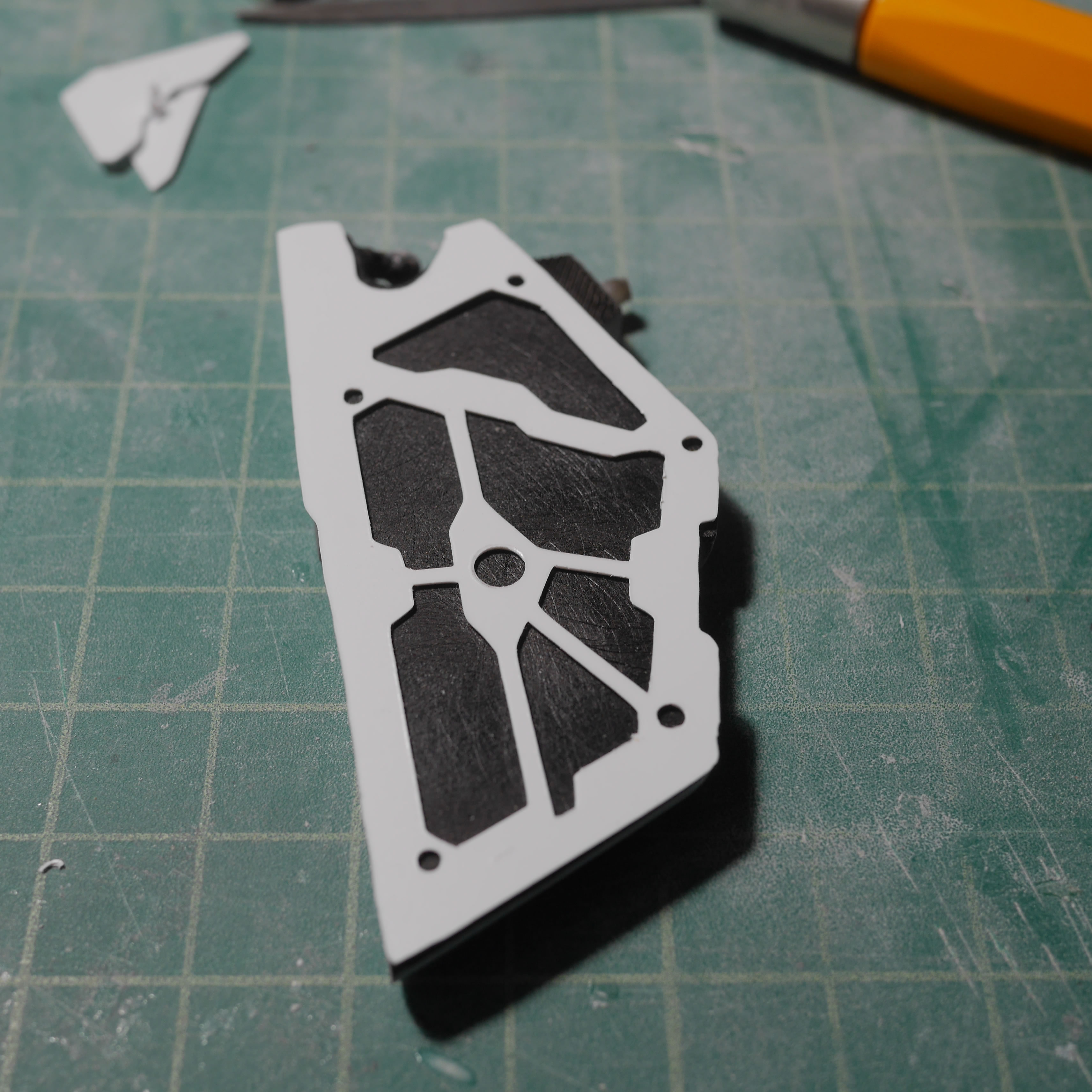
The front skirt pieces are just glued to the original skirt. A quick look at the rather thin front skirts. This will be fixed soon enough.
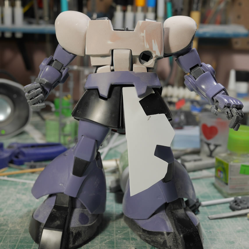
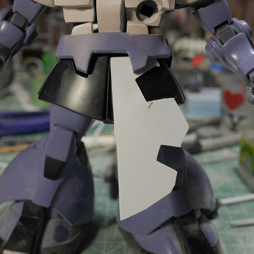
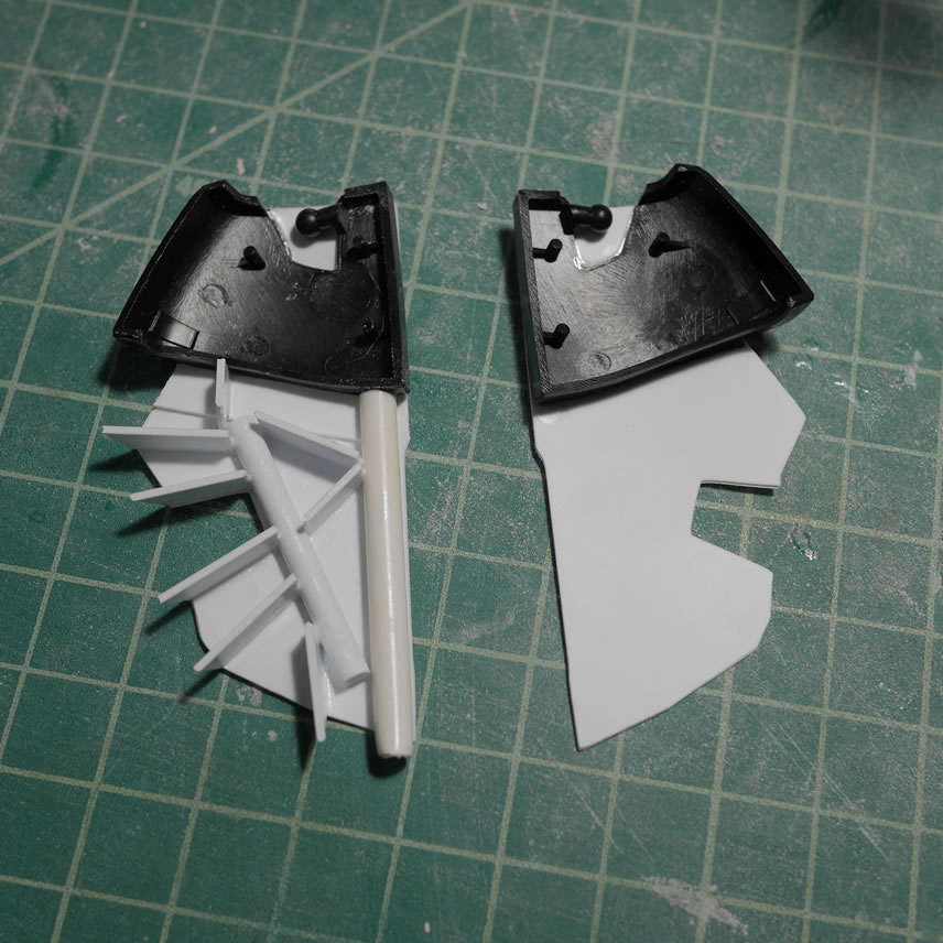
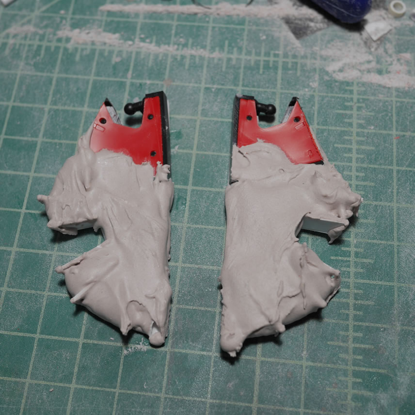
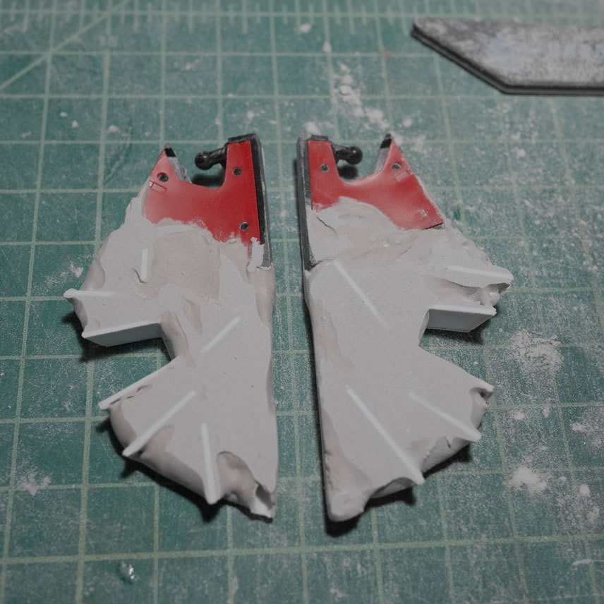
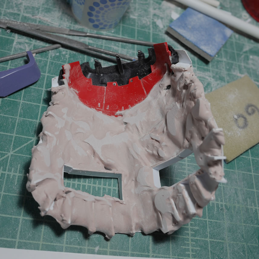
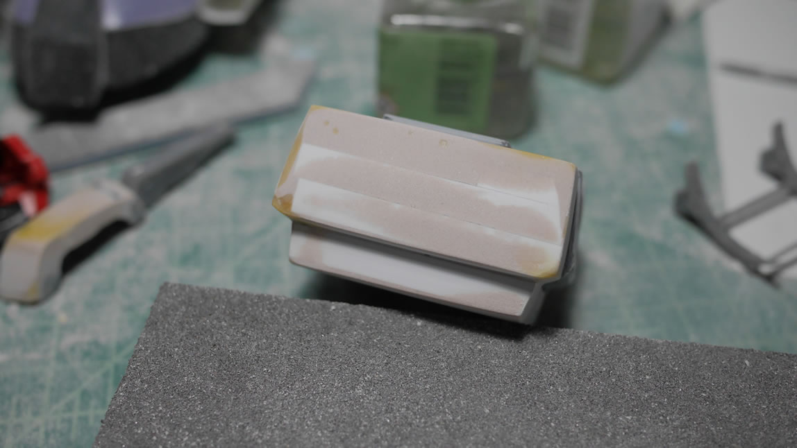
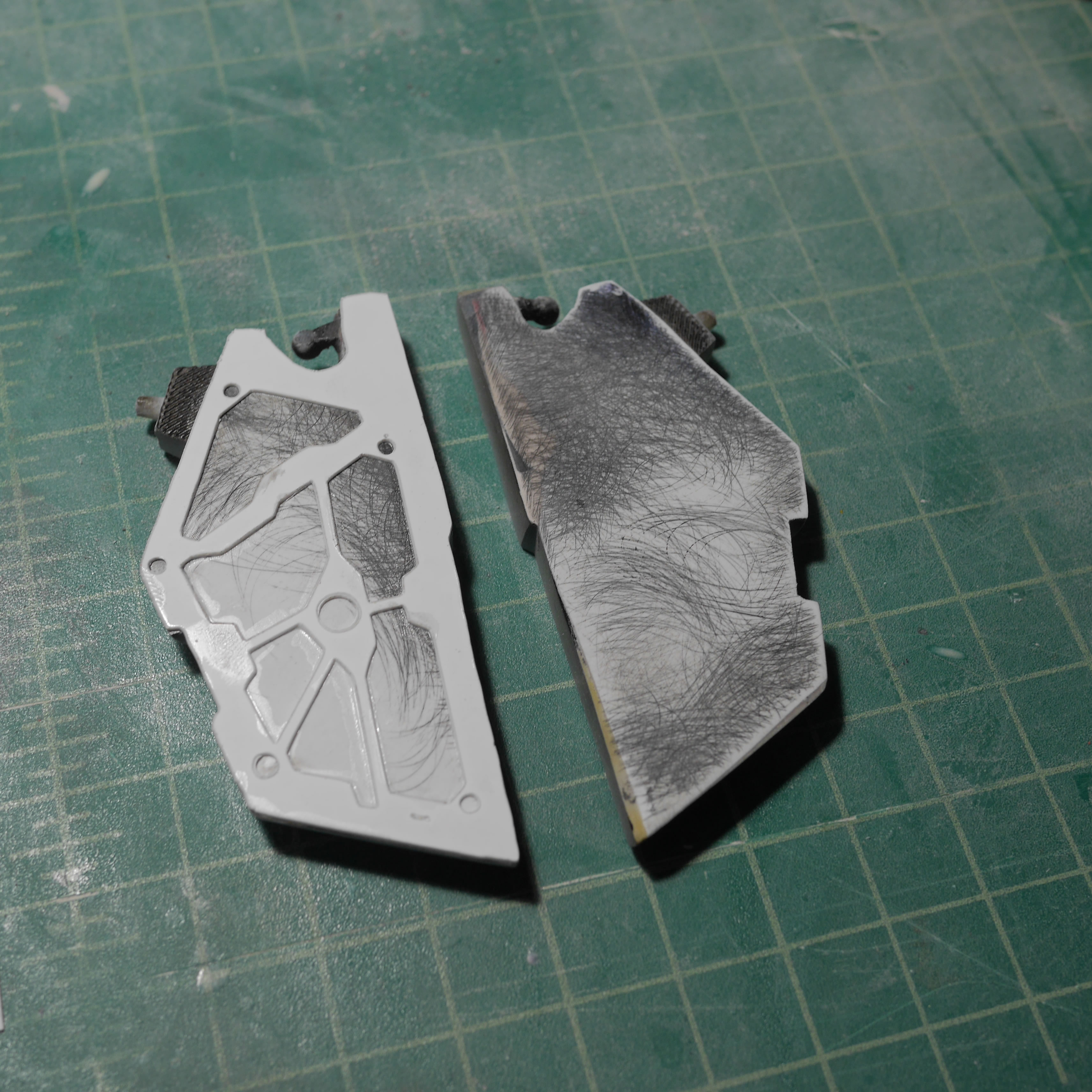
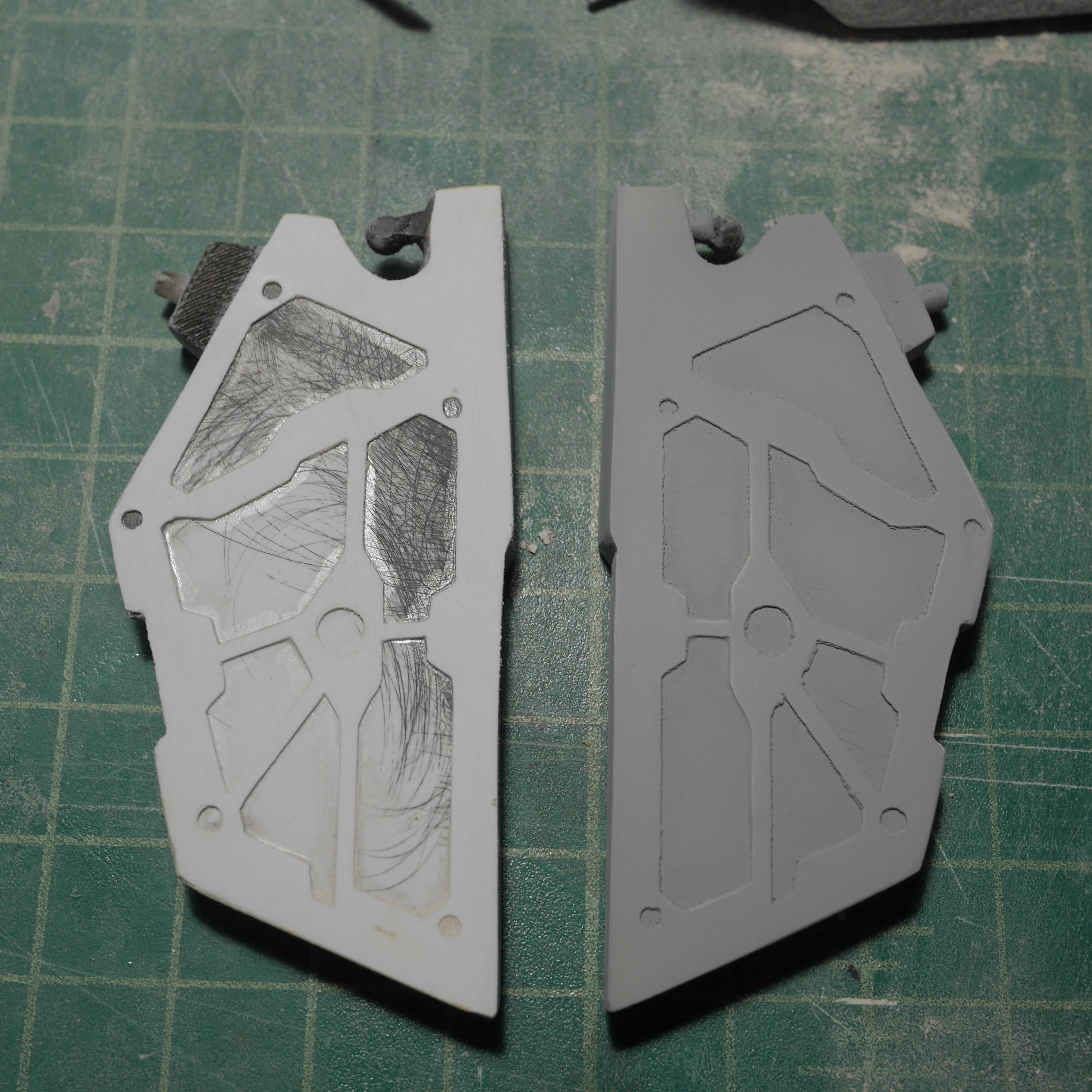
As with everything else so far. As we all need structure in our lives, the front skirts also need structure. I randomly glue in plastic. Once this is set, polyester putty is slapped on. The structure gives the putty something to grab.
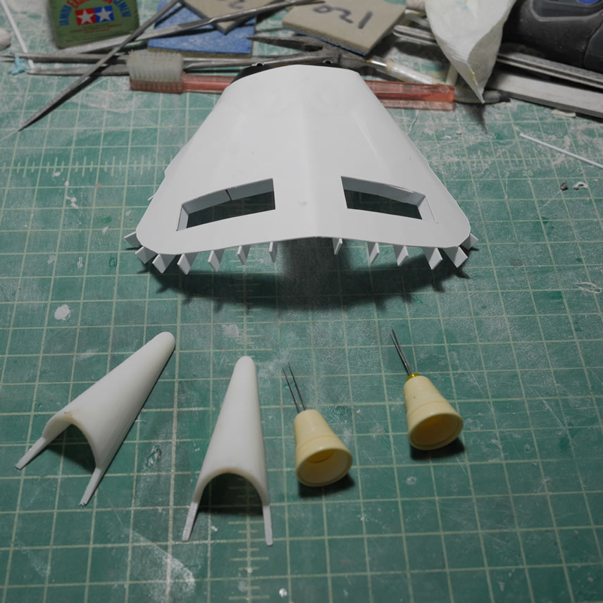
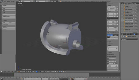
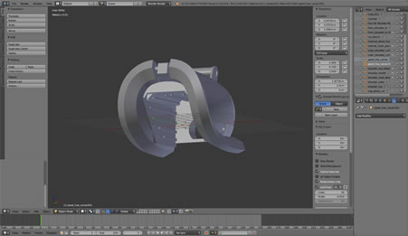
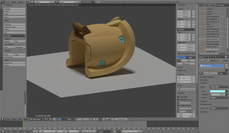
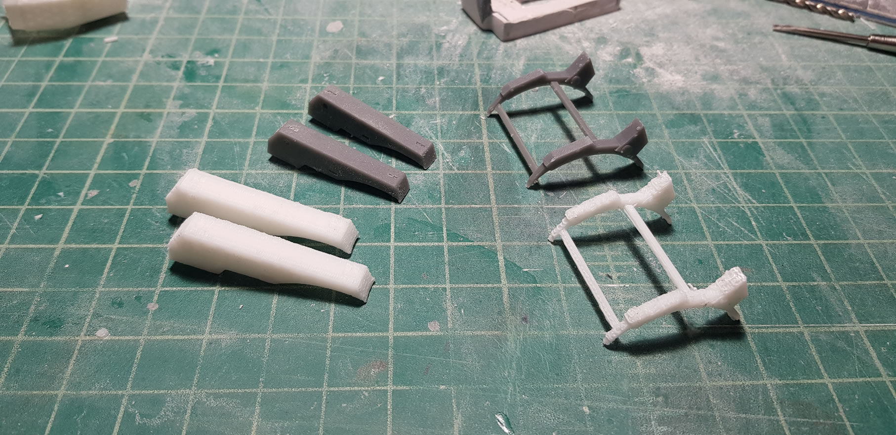
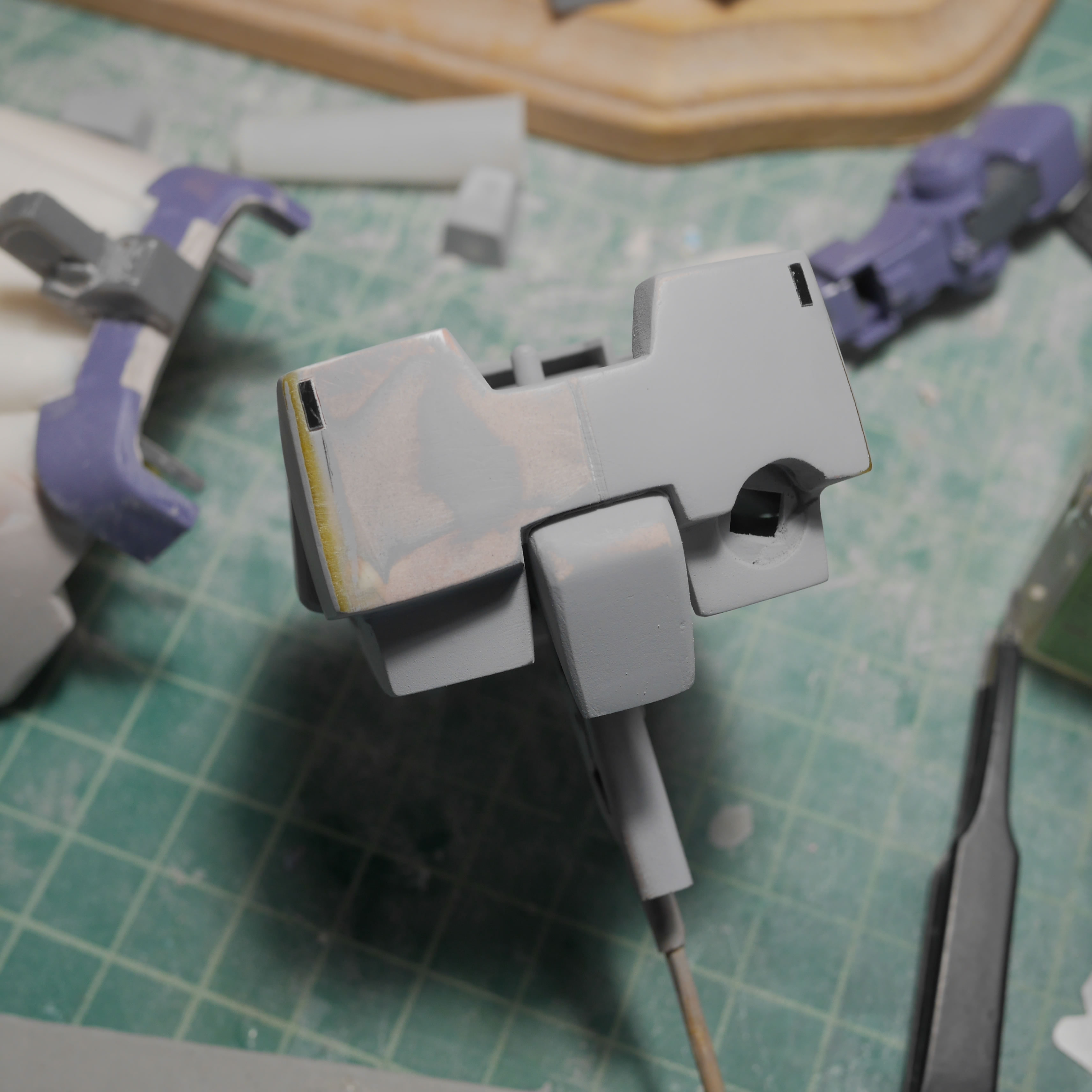
While that stinks up my room, I set it aside to cure and move to the other side of my workshop to design some new thrusters for the back of the lower legs. The original thrusters are too short and from the reference pictures, the new thrusters look much longer, so a quick design session on blender and I have new thrusters for the back legs.
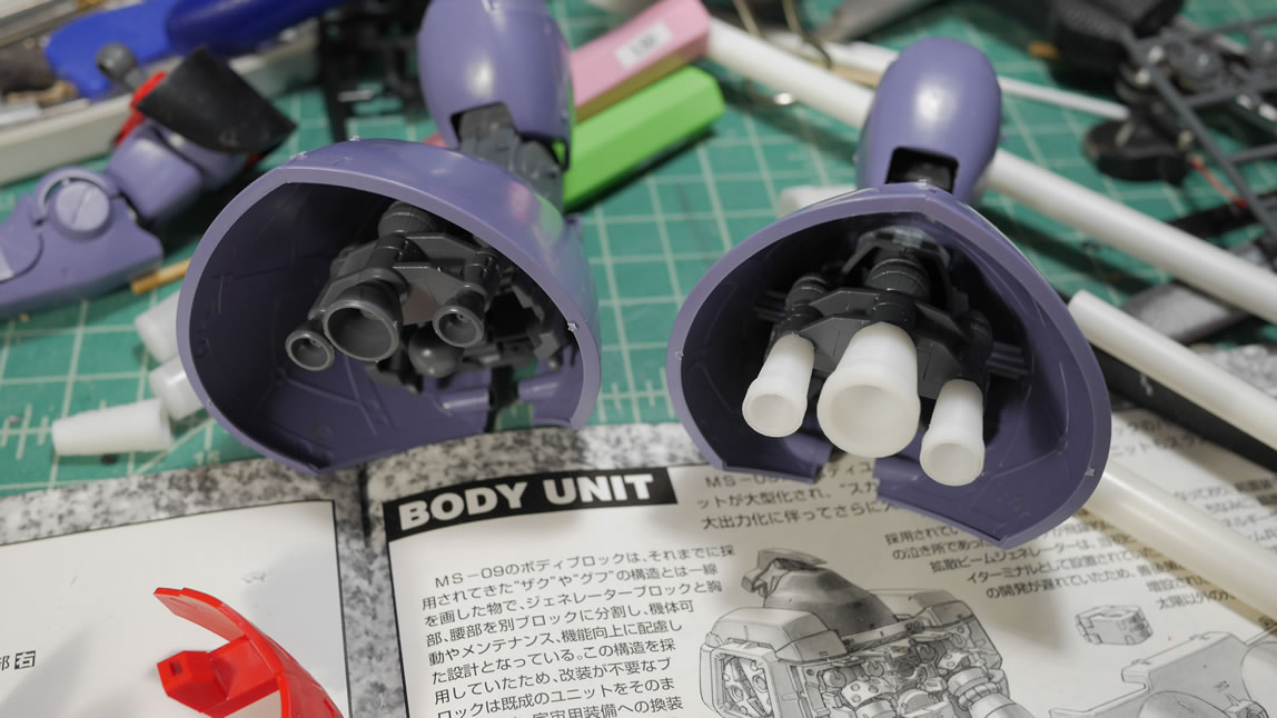
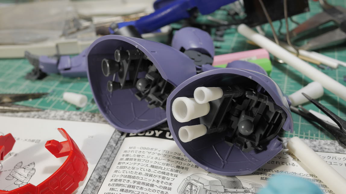
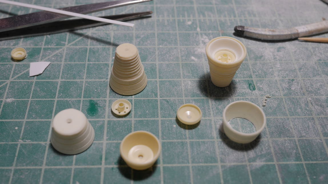
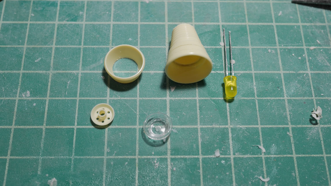
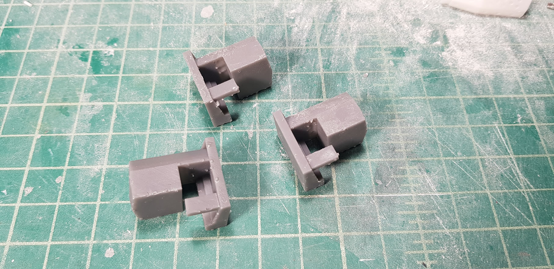
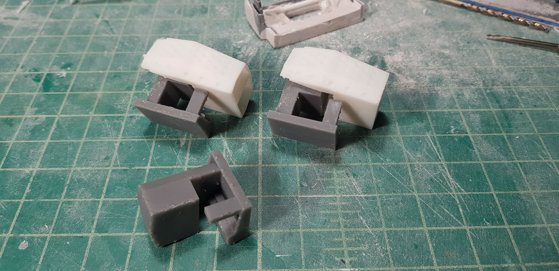
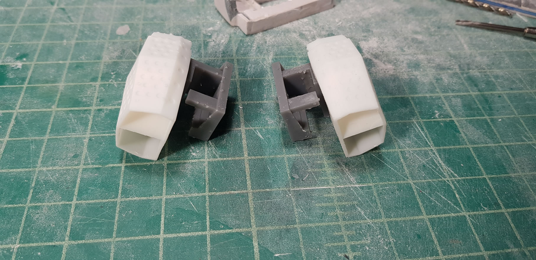
Continuing on to other thruster work, the back skirts have some massive thrusters. I know that I have some resin copies of metal thrusters to I want to try to see if I can make something work here first before resorting to the 3D printer like the previous (I couldn’t find something that fit, so I had to make some). I glued a few thruster bells together and made some more casts of the other pieces. The nice part of having thruster bells with so many different internal pieces is that I can do some interesting things. I casted one of the internal bell pieces in clear resin. Then assembling them and adding a light at the end of the tunnel, I can effectively create a halo effect within the thruster bell and use the design gimmicks of the center bell piece to allow light through small holes. I think this is a pretty cool effect.

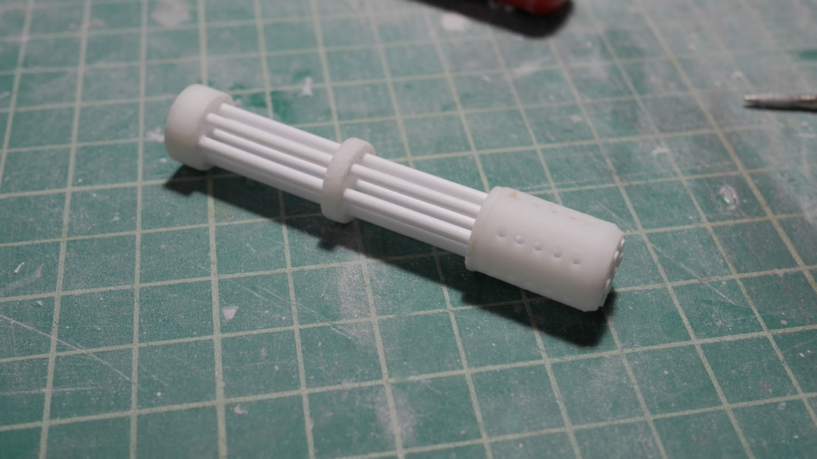
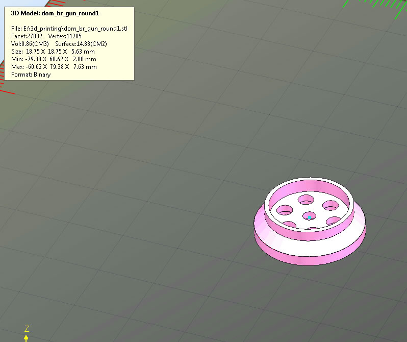
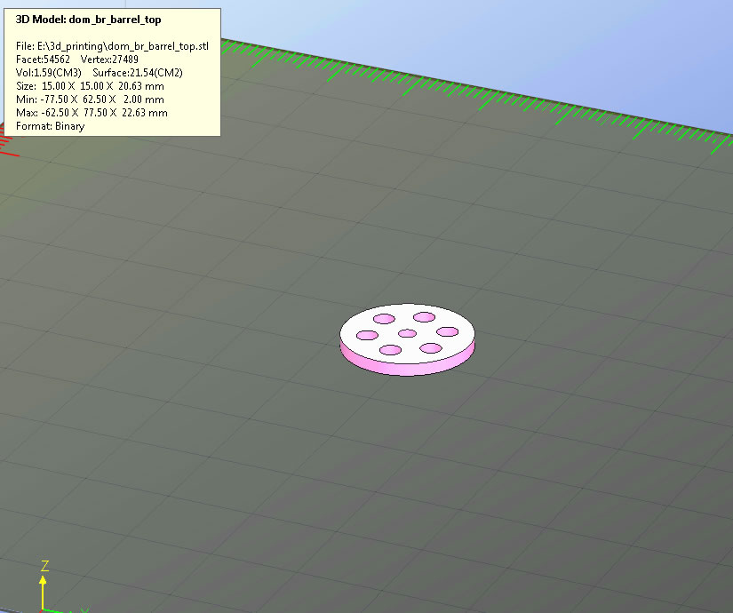
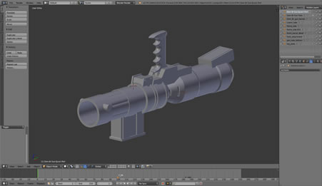
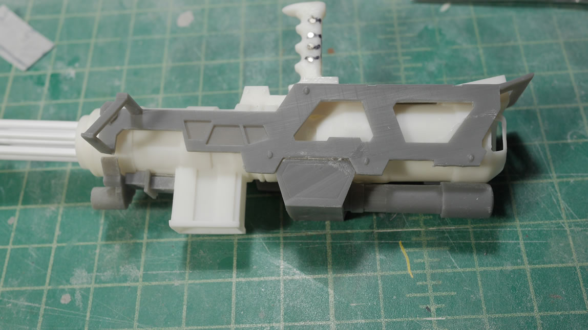
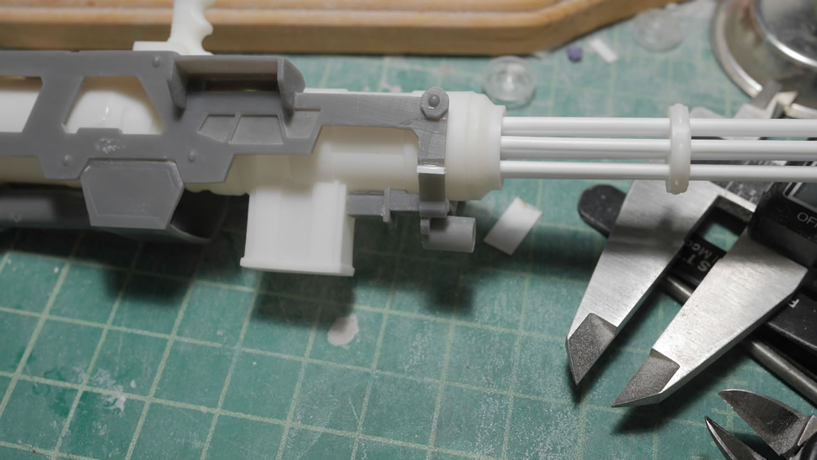
Next up, we go back to blender and design a front gun barrel. This is much easier than measure and drilling out holes that are completely lined up and spaced evenly. The center structures to the gun barrel are also designed and printed. The barrels will be styrene tubes.
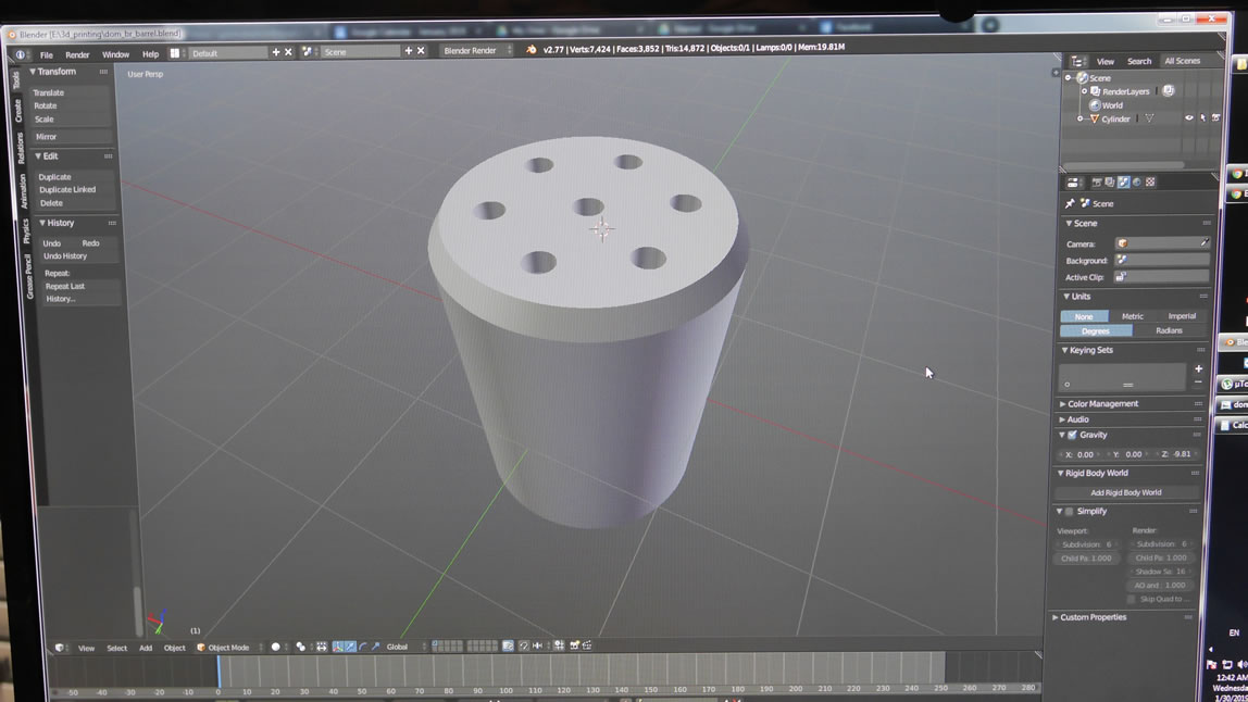
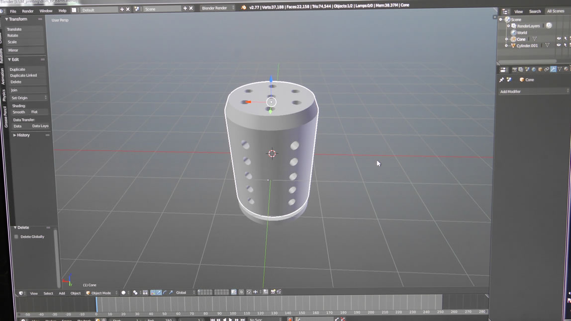
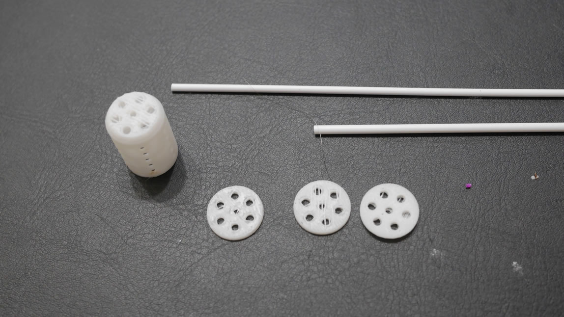
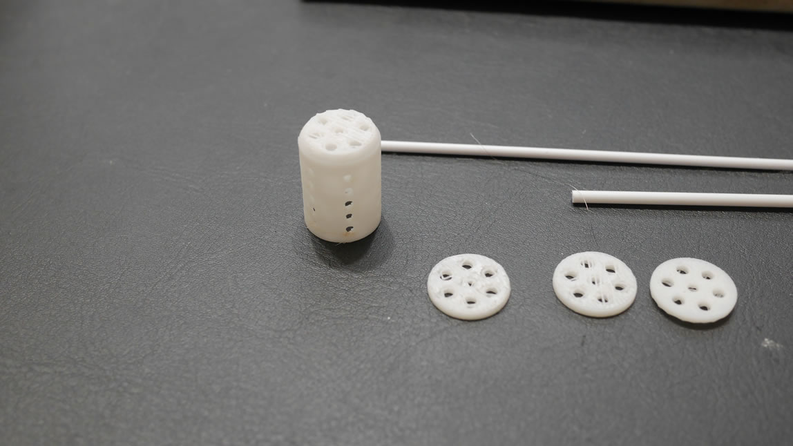
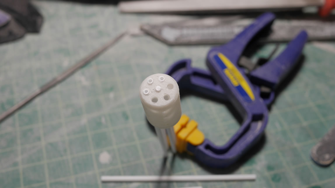
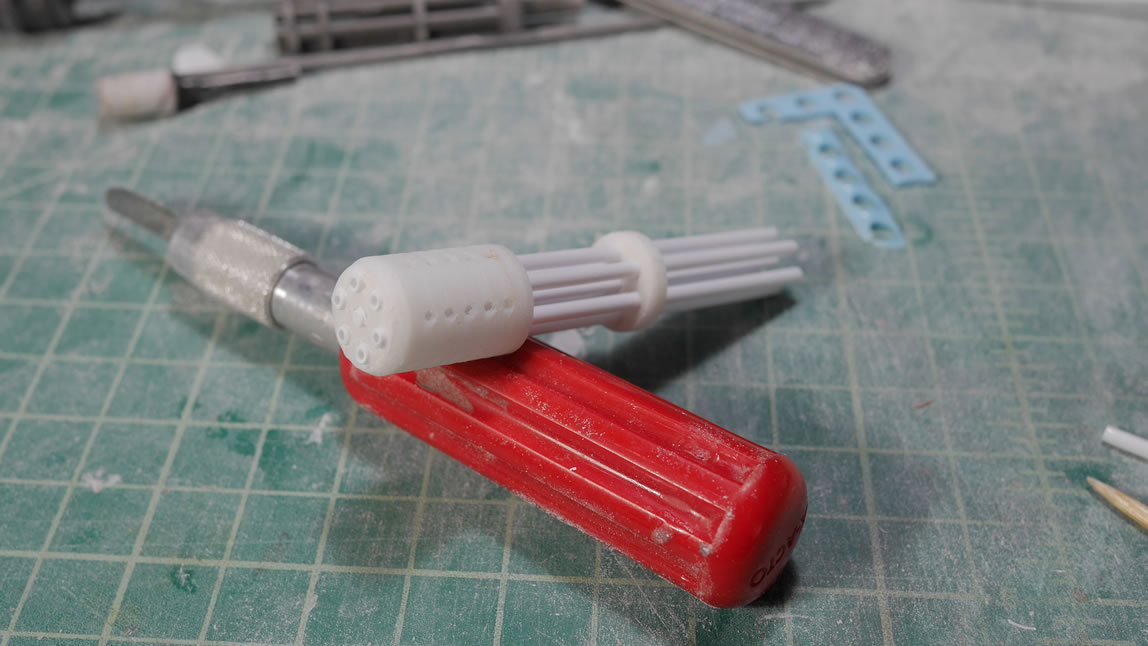
Pushing the tubes and rods through the printed piece I get a general idea of what the first third of the gun looks like. I will make adjustments after I make more reference measurements and modify things as I continue to build.
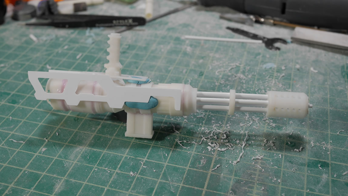
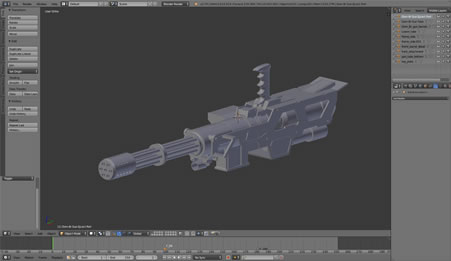
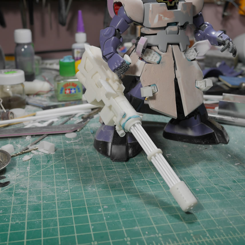
Frame pieces for the gun are designed and cut in the die cutter. The main gun assembly pieces were all designed in blender and 3D printed. I printed in sections for easy printing and easier assembly. Here is a quick mock up of the gun. This is very rough, but I get a better idea of where to make adjustments and I have something I can see.
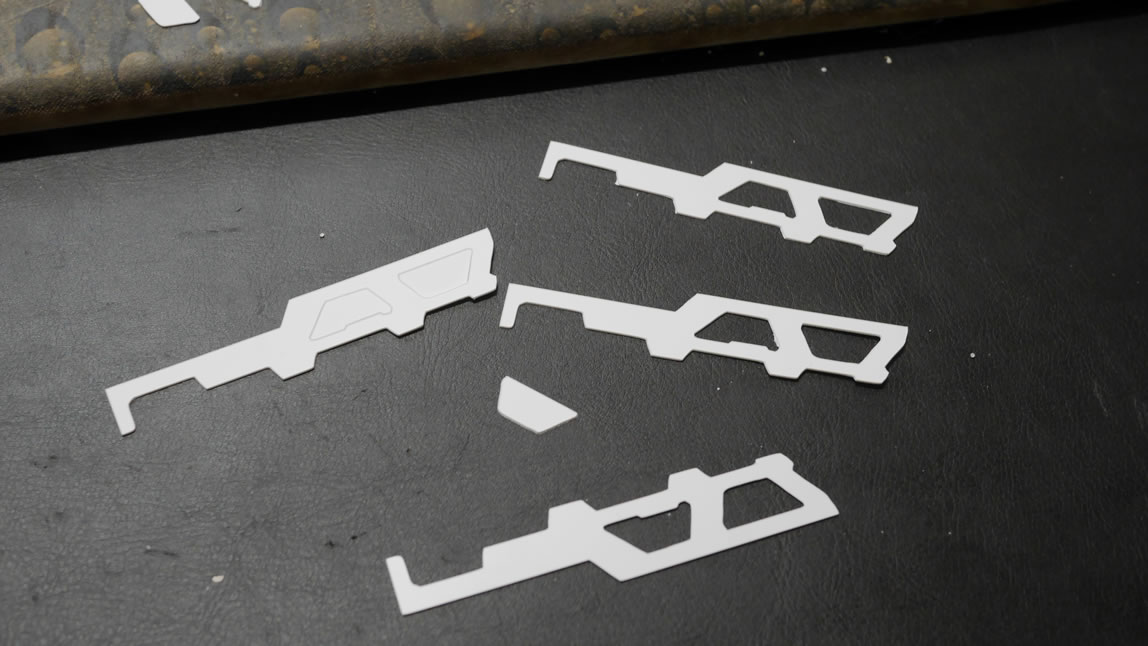
The original frame pieces were a little too small for my liking, so I made some adjustments and cut new ones and here I have all the gun pieces laid out. I designed and printed out the spent shells exhaust port as well as the ammo belt feed attachment point.
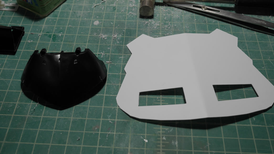
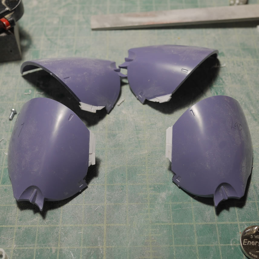
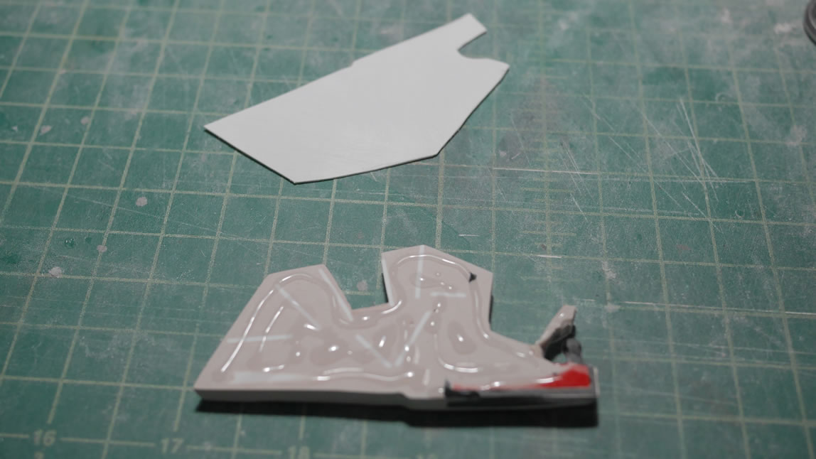
Rear skirt is drawn and cut on .4mm plastic. Here is a comparison to the original rear skirt.
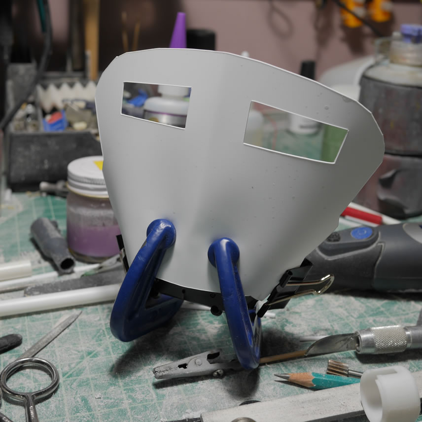
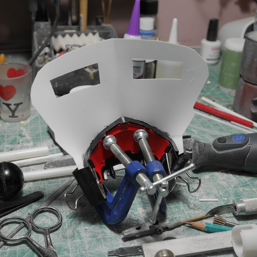
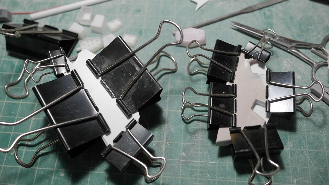
Clamps are used to hold the flat plastic sheet against the curvy rear skirt piece while the glue sets up. Very similar to how the front skirts were initially built.
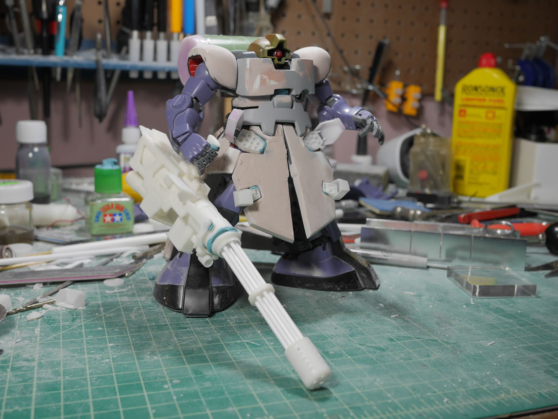
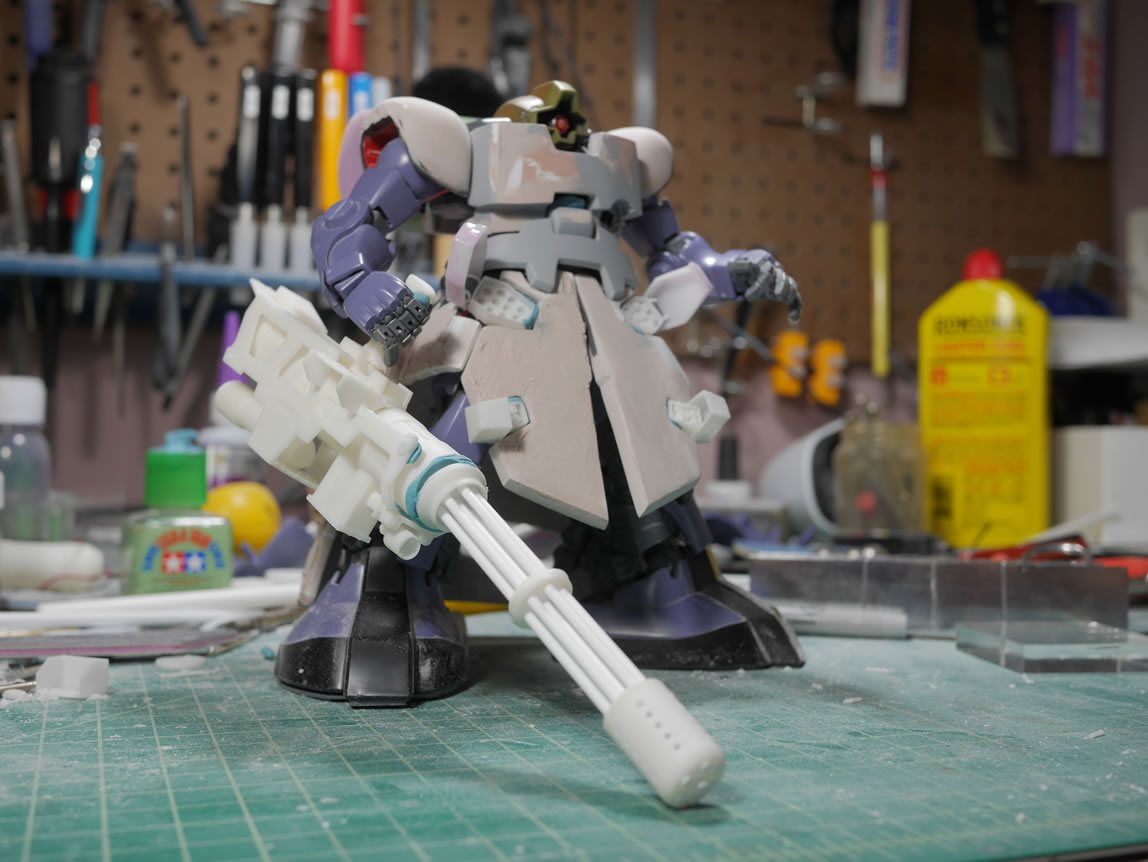
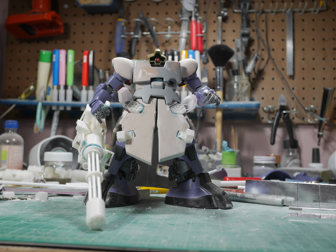
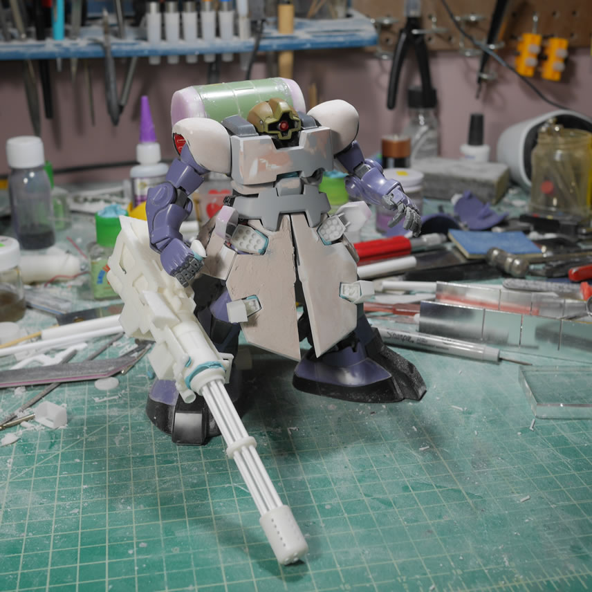
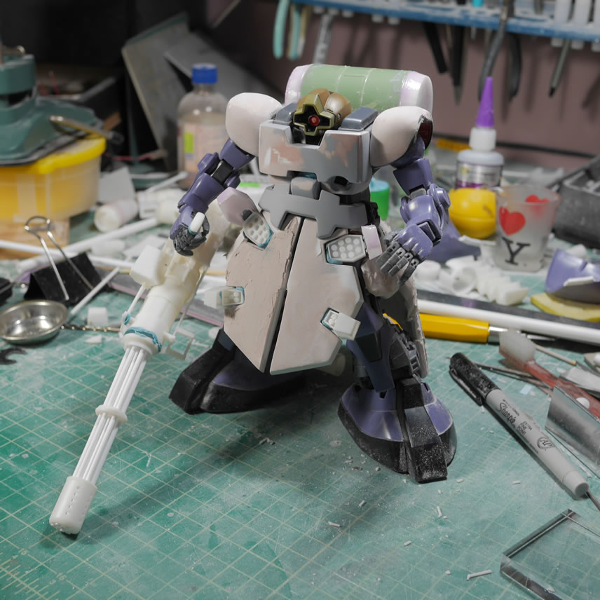
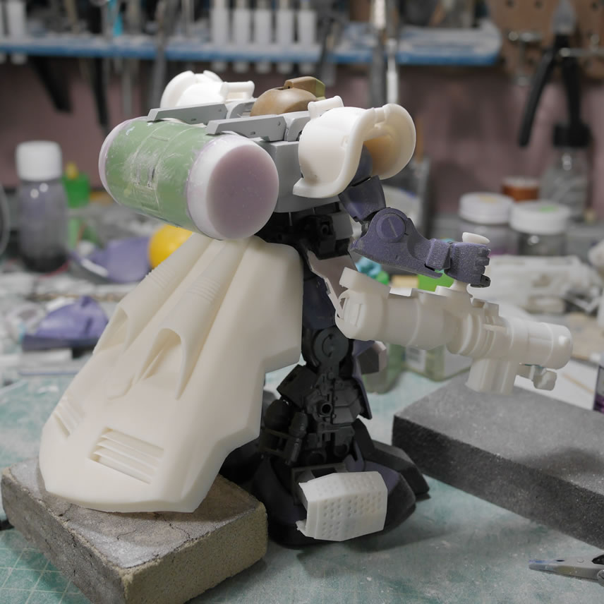
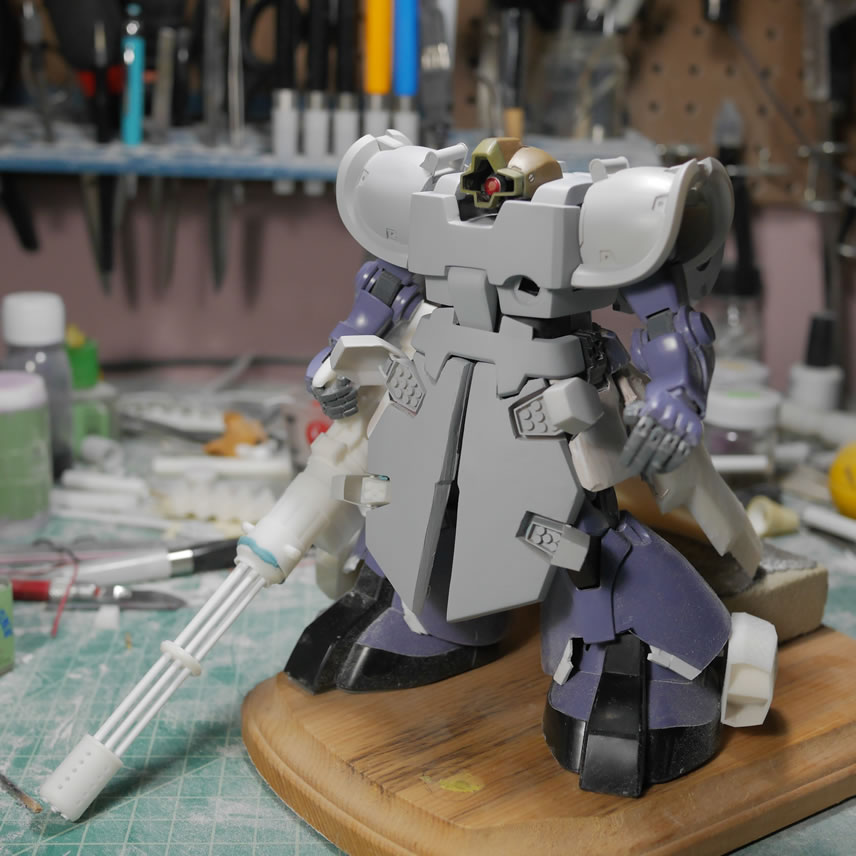
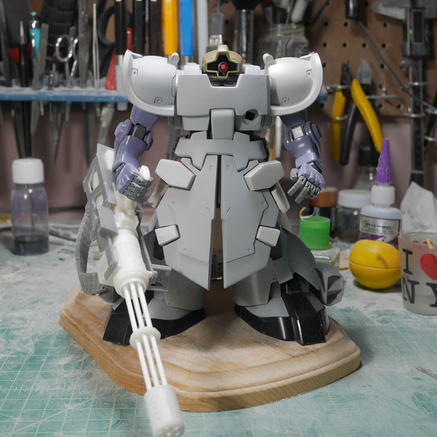
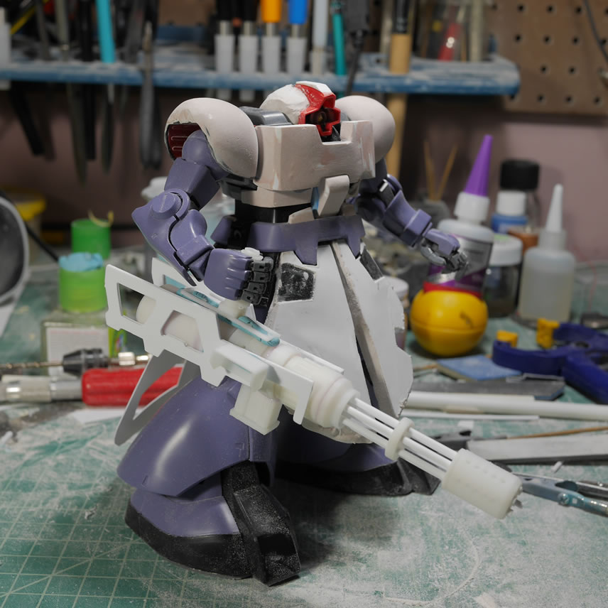
And here is what the project looks like so far. The adjusted gun design; the chest, front skirts, backpack and rear skirt. Not too shabby for about 2 weeks work of work so far.

February 12, 2019: Progress slowed down a bit because I spent a few days making a mold of a crappy Thai made resin recast of Faye Valentine that a friend of mine picked up back in 2003. The resin is so brittle and ceramic like in texture that it is near impossible to work with and sand. I had made some casts of the Dom’s leg thruster parts and had extra silicone to make one of the Faye parts and after that one piece, I just fell down the rabbit hole.
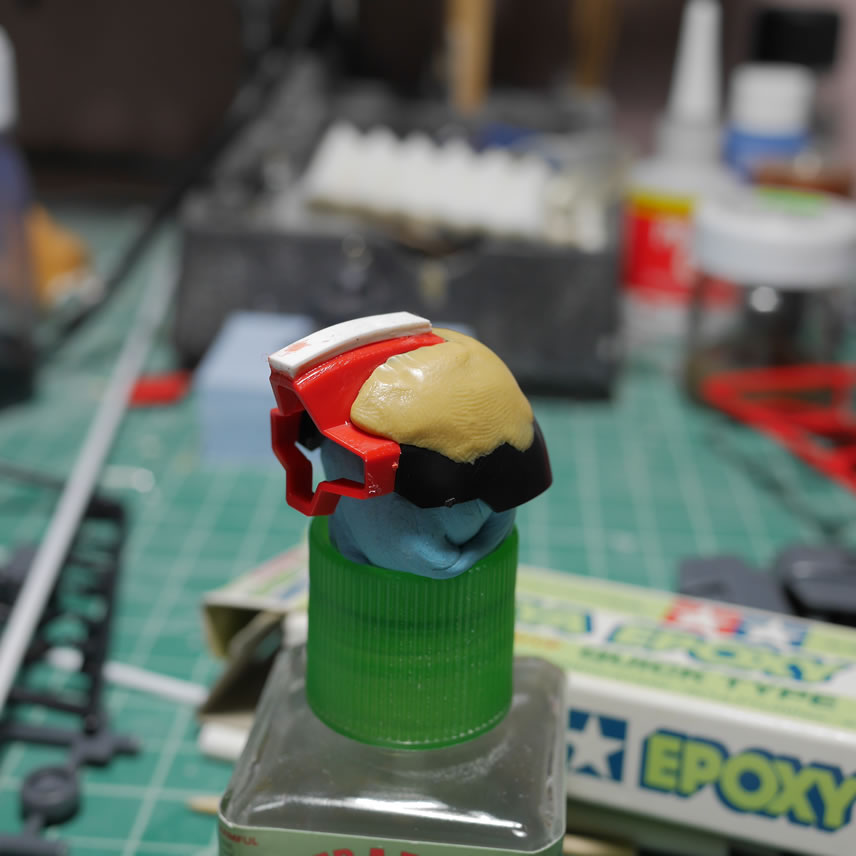
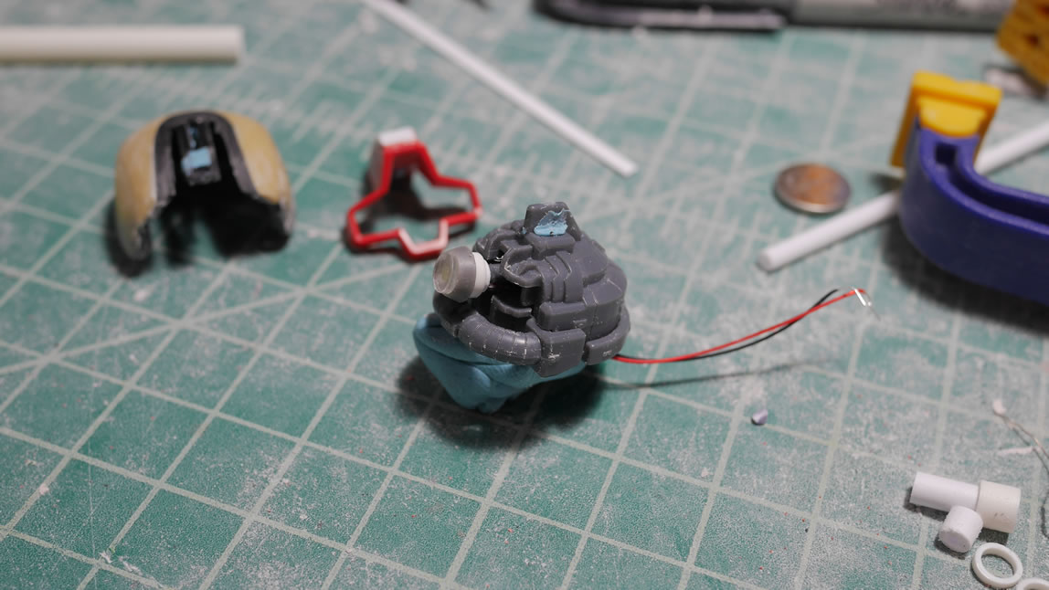
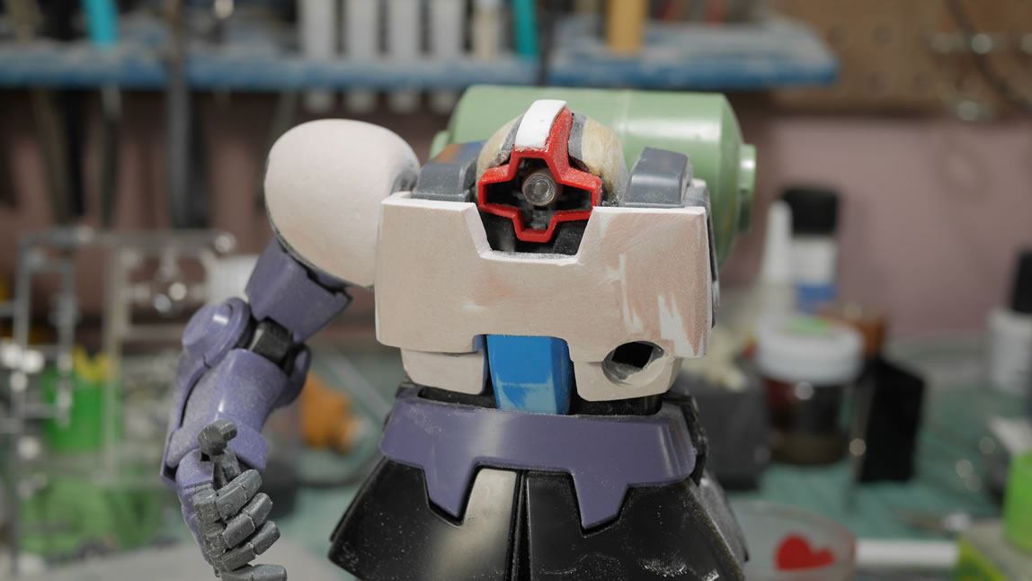
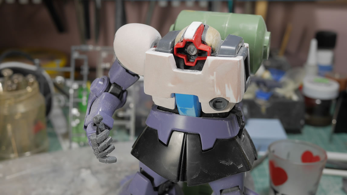
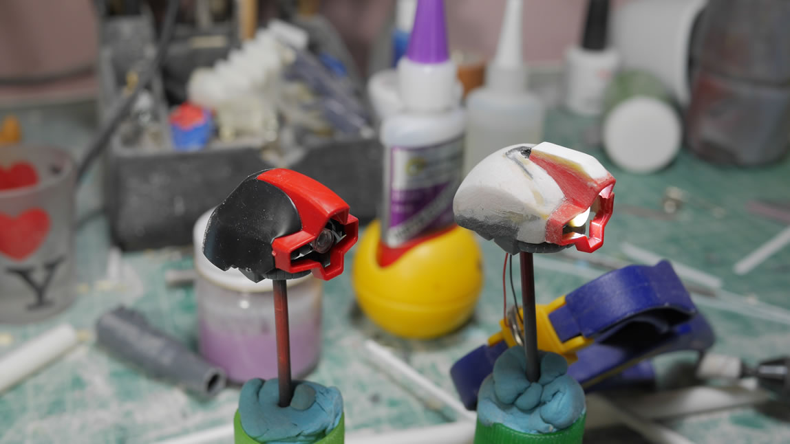
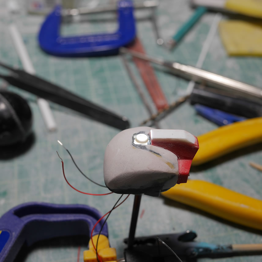
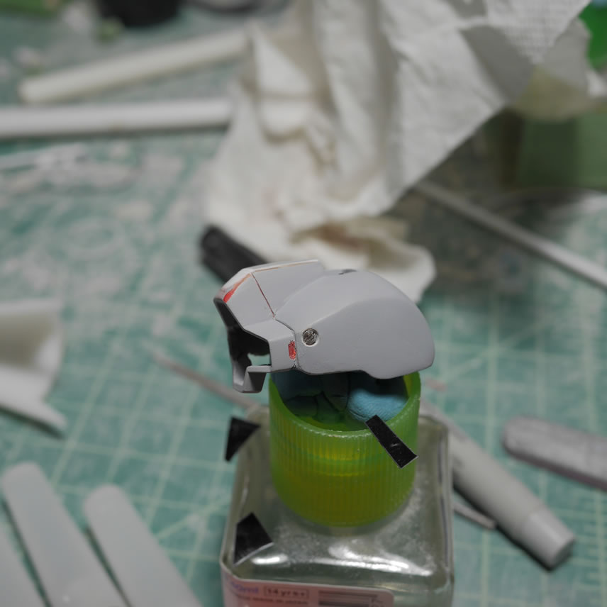
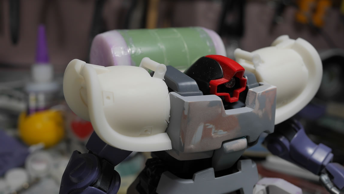
But back to work on the kit and like the last post, I will try to keep things organized towards the sections I got work on since the last update. First up is the work on the head. I started with tamiya epoxy putty quick type but that stuff takes a little too long and is pretty hard to sand, so I switched over to the polyester putty. And here are some comparison pictures to the original head. I also got the LED wired up and tested that look as well.
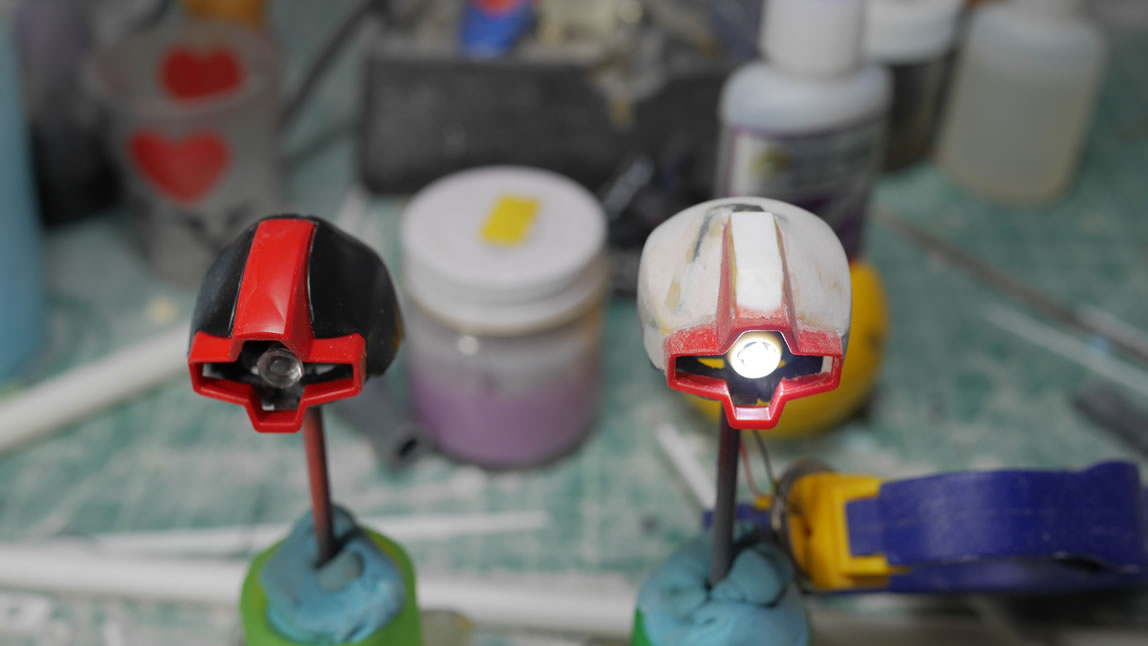
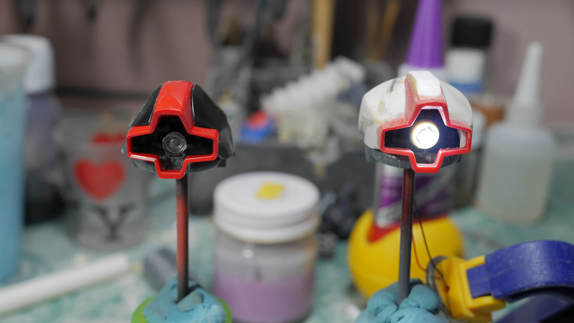
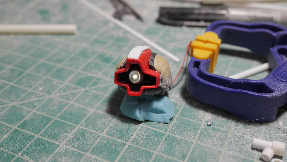
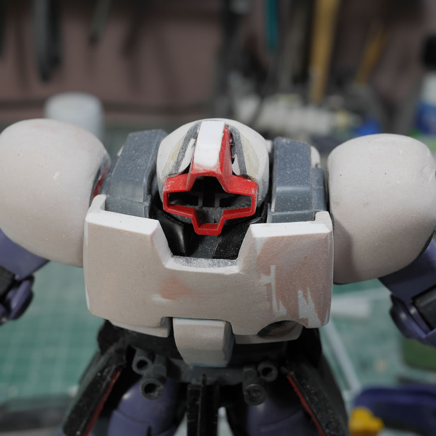
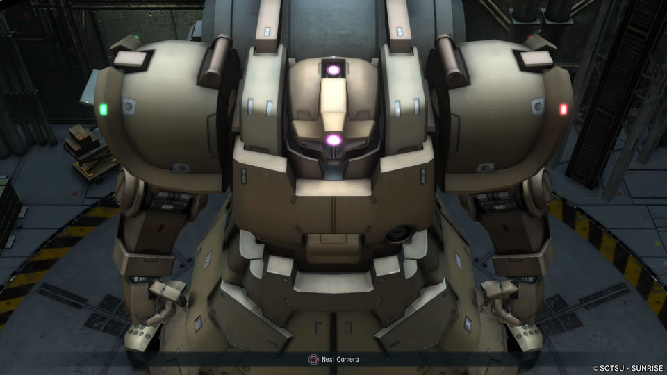
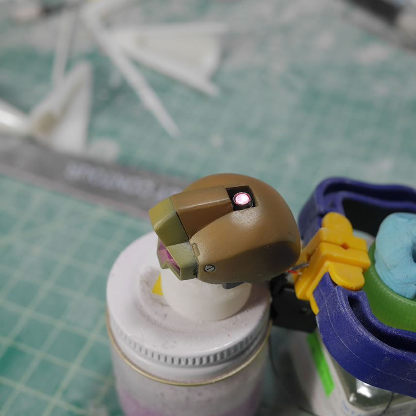
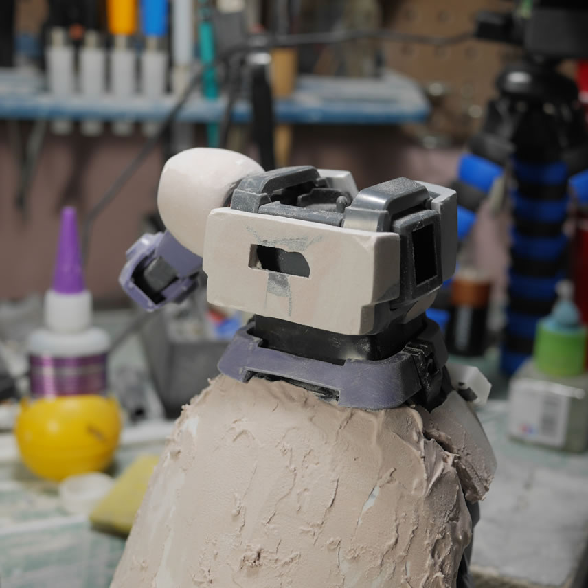
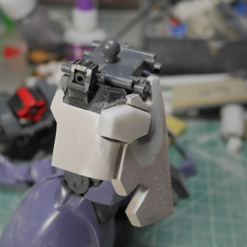
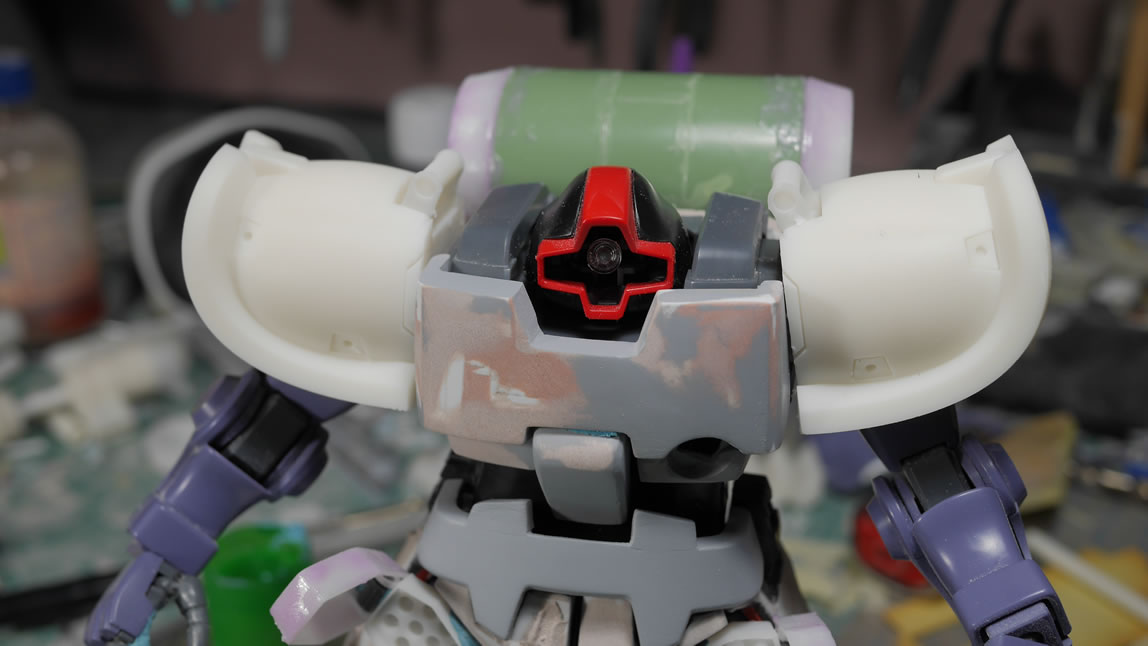
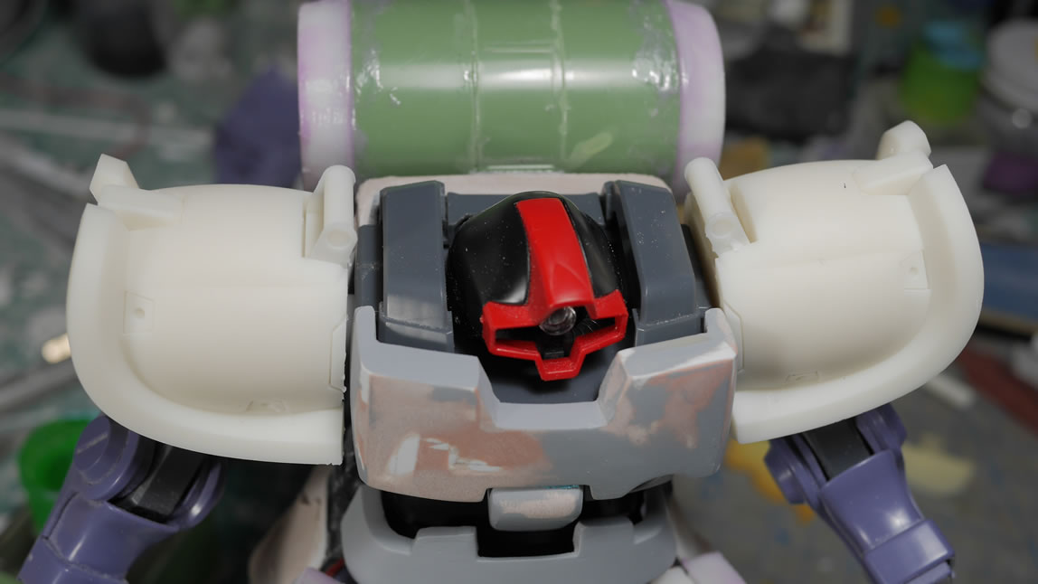
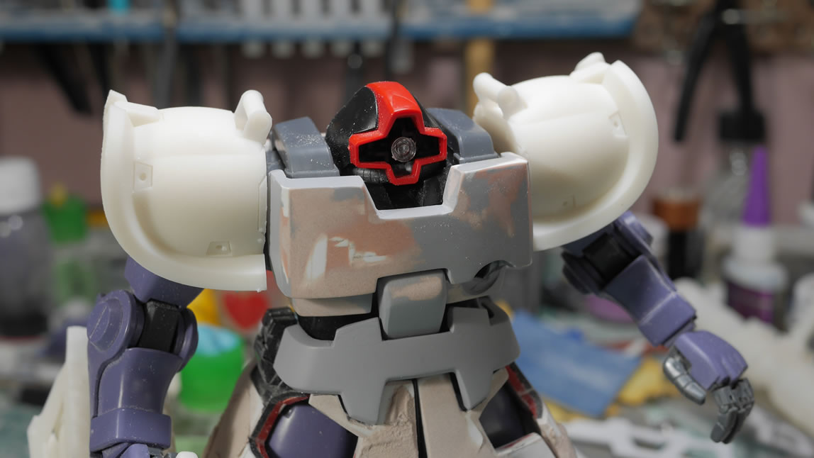
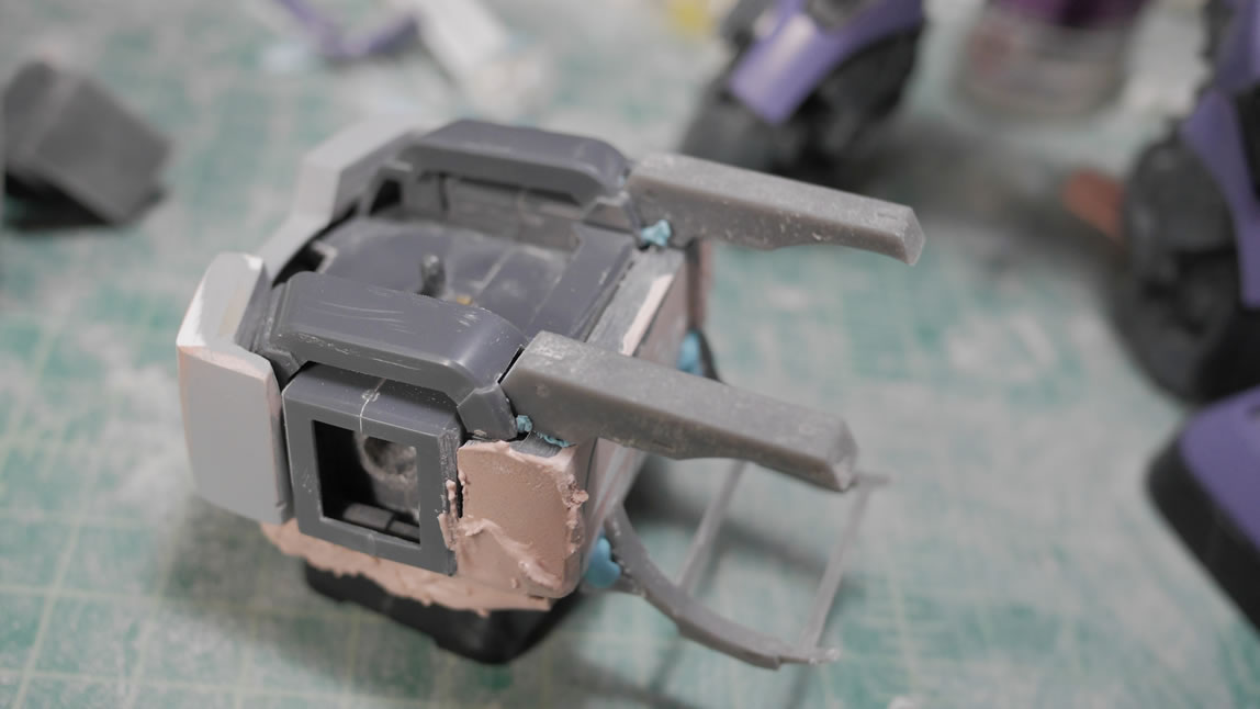
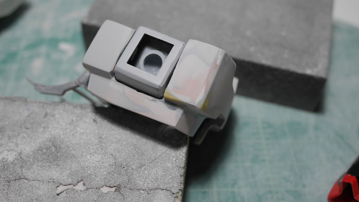
A little interesting thing I saw while taking screen shots of the thing off Gundam Battle Operation 2. This Dom has a second camera mono eye on the top of it’s head. I guess this makes sense since the forward facing mono eye has limited view since the majority of the head is blocked by giant shoulders. So to keep with the reference materials, I add this modification to the head as well.
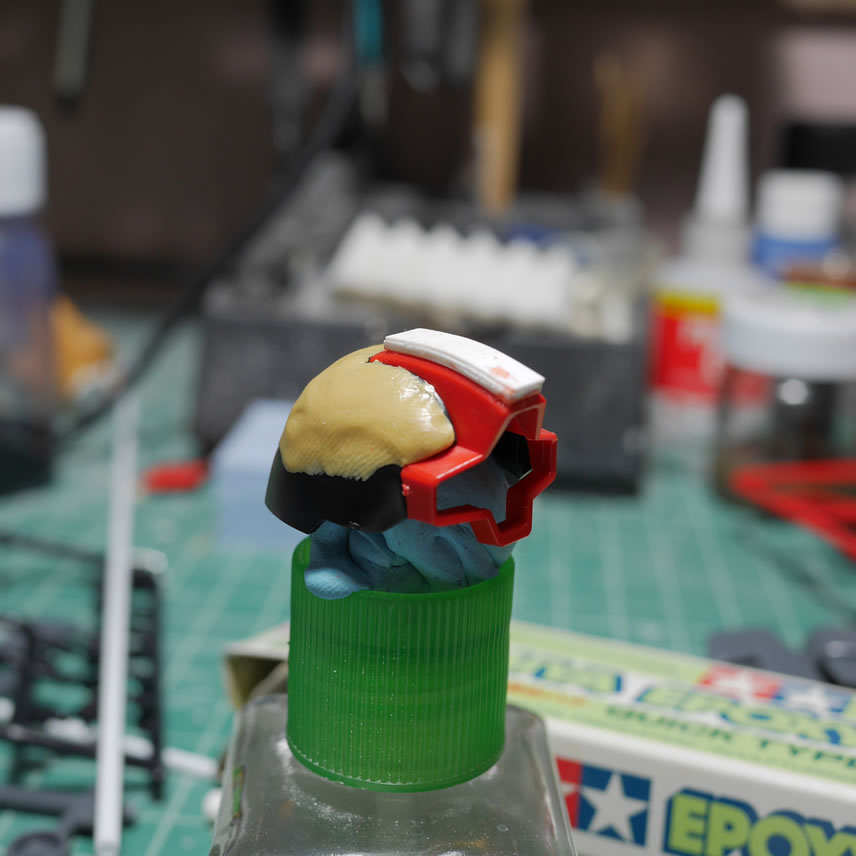
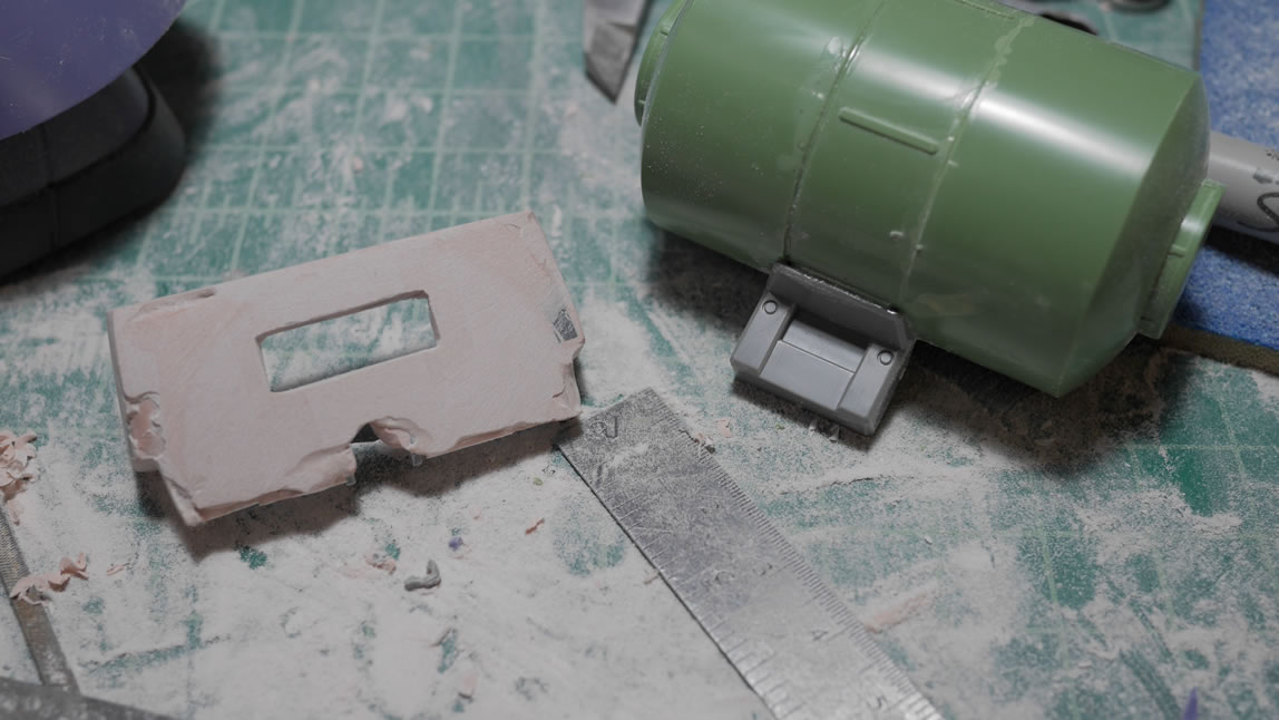
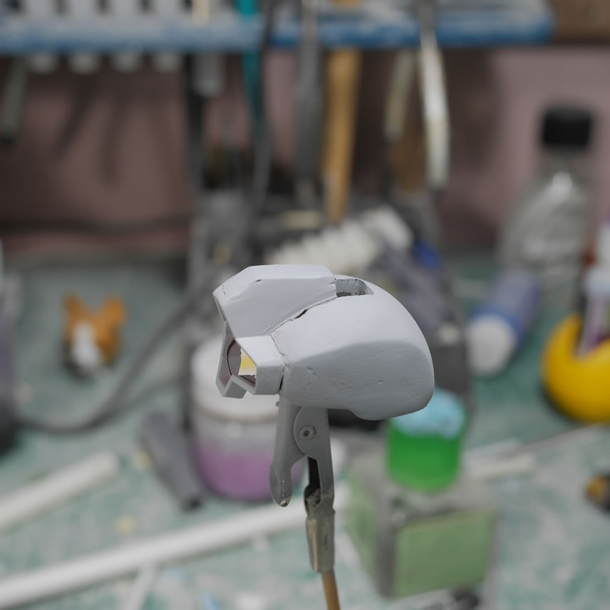
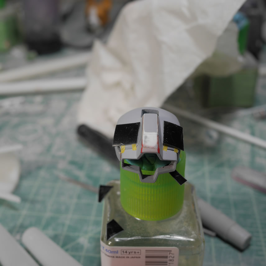
The visor piece was cut and I drilled out the top of the head. Once I had a pilot hole drilled out, I used metal files to start shaping out the square opening. For the internal piece, I cut the top of the part and sanded it down so that I could glue a piece of styrene tube. This will hold the second head LED as well as the camera lens. A quick test assembly is done to make sure everything works. The last picture shows the parts of the head. The additional SMD LED wired, the modification to the inner head, the lens, and the head armor.
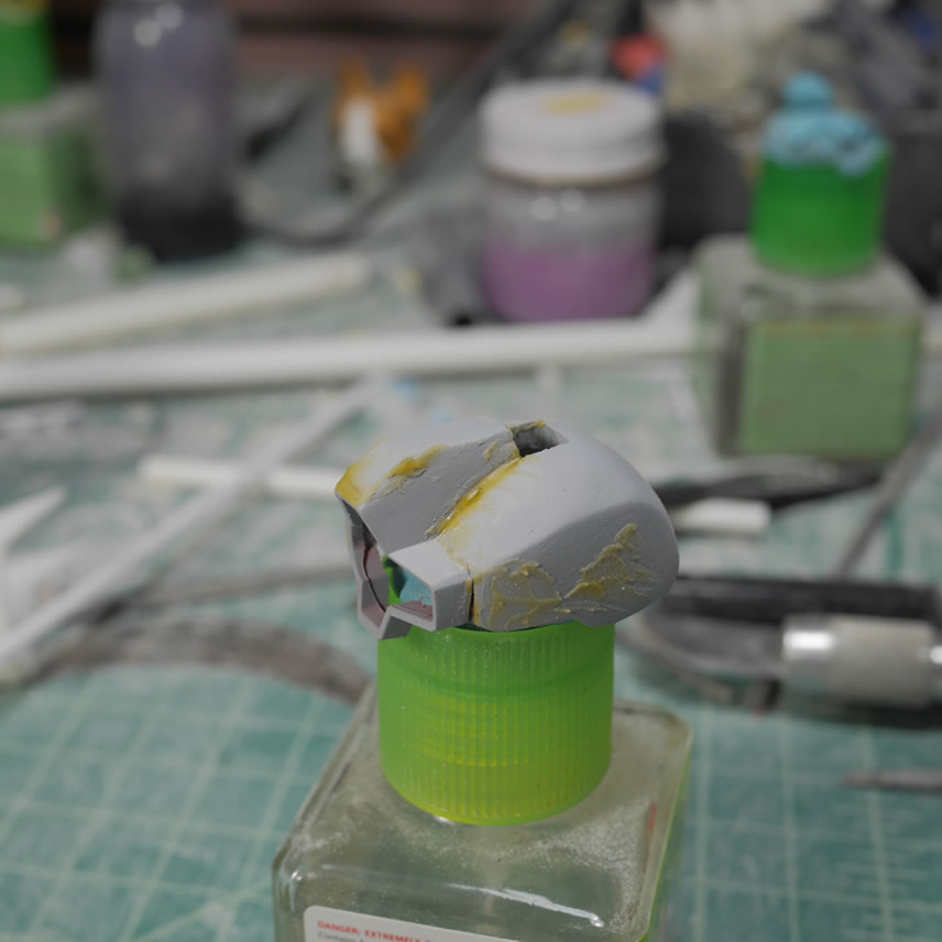
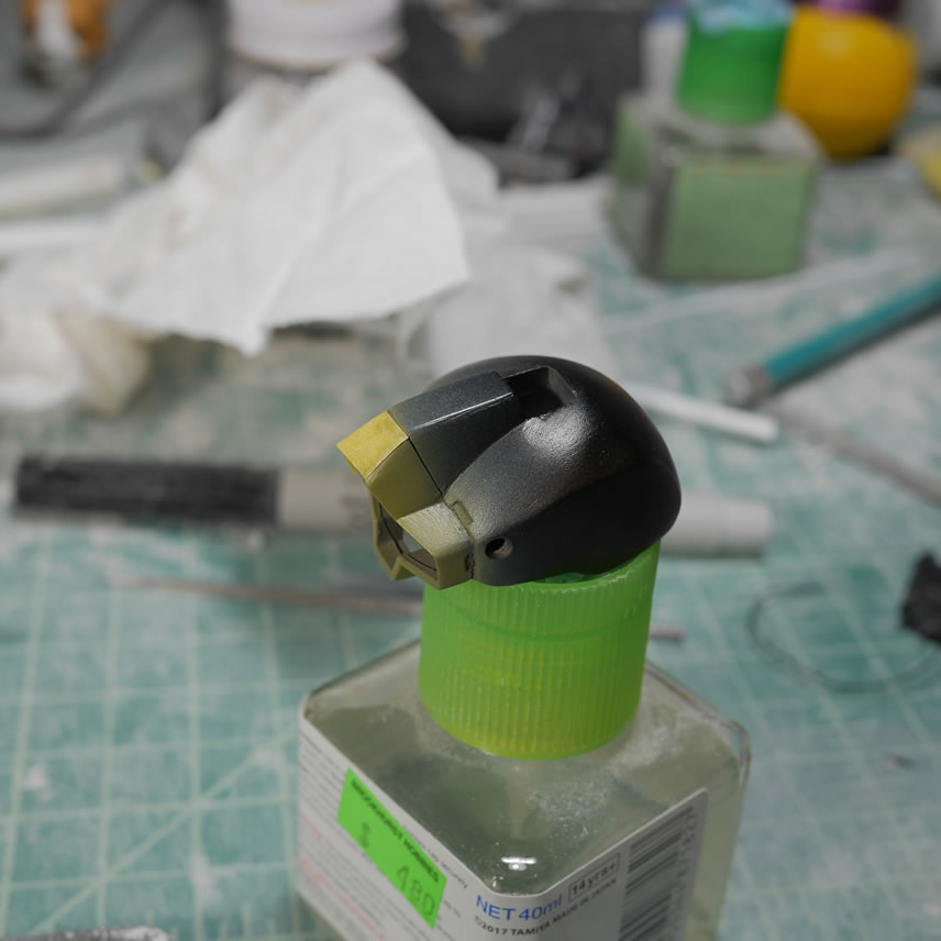
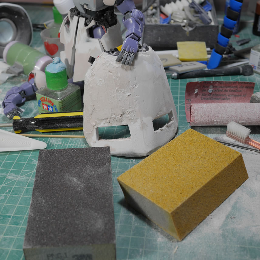
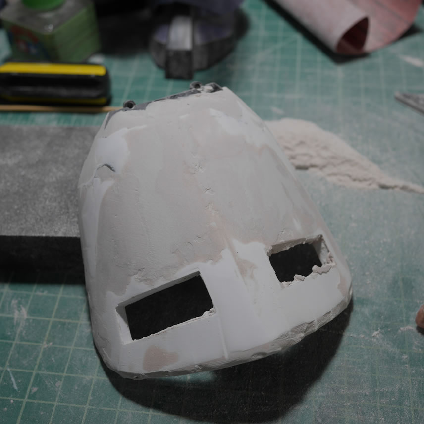
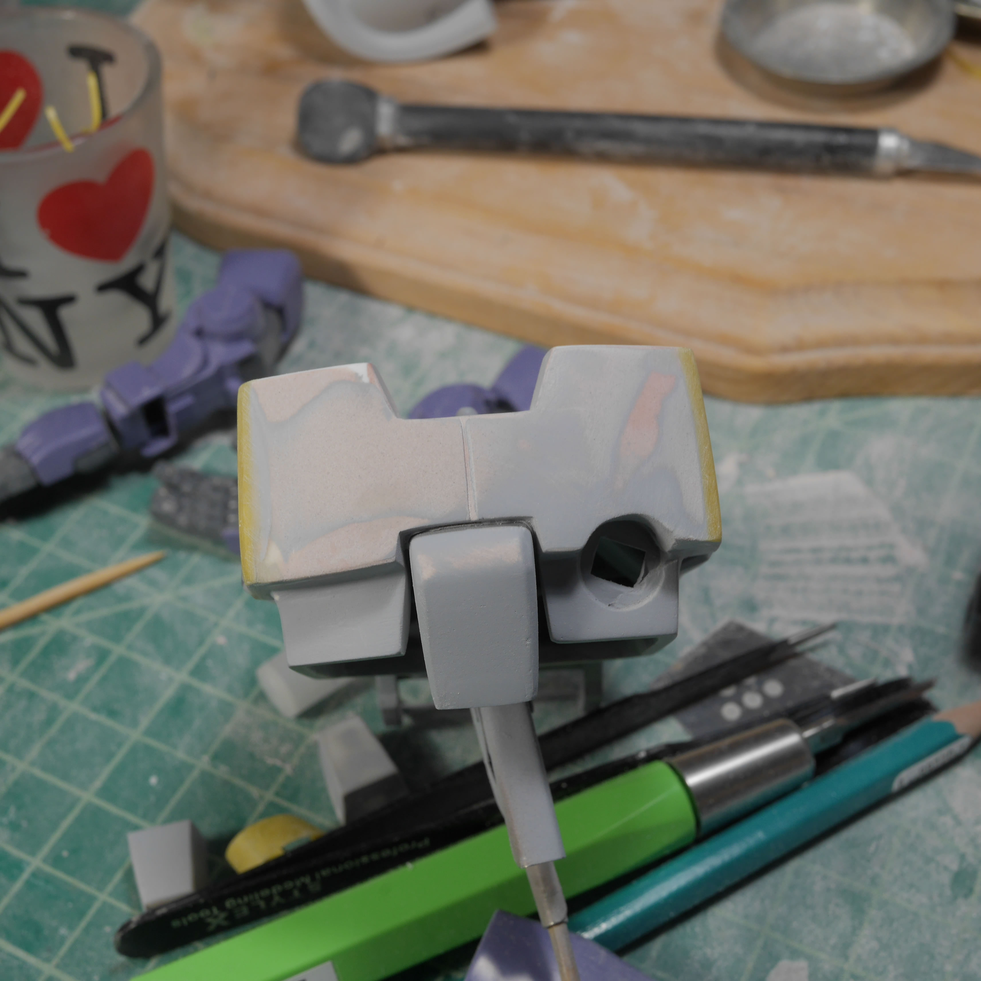
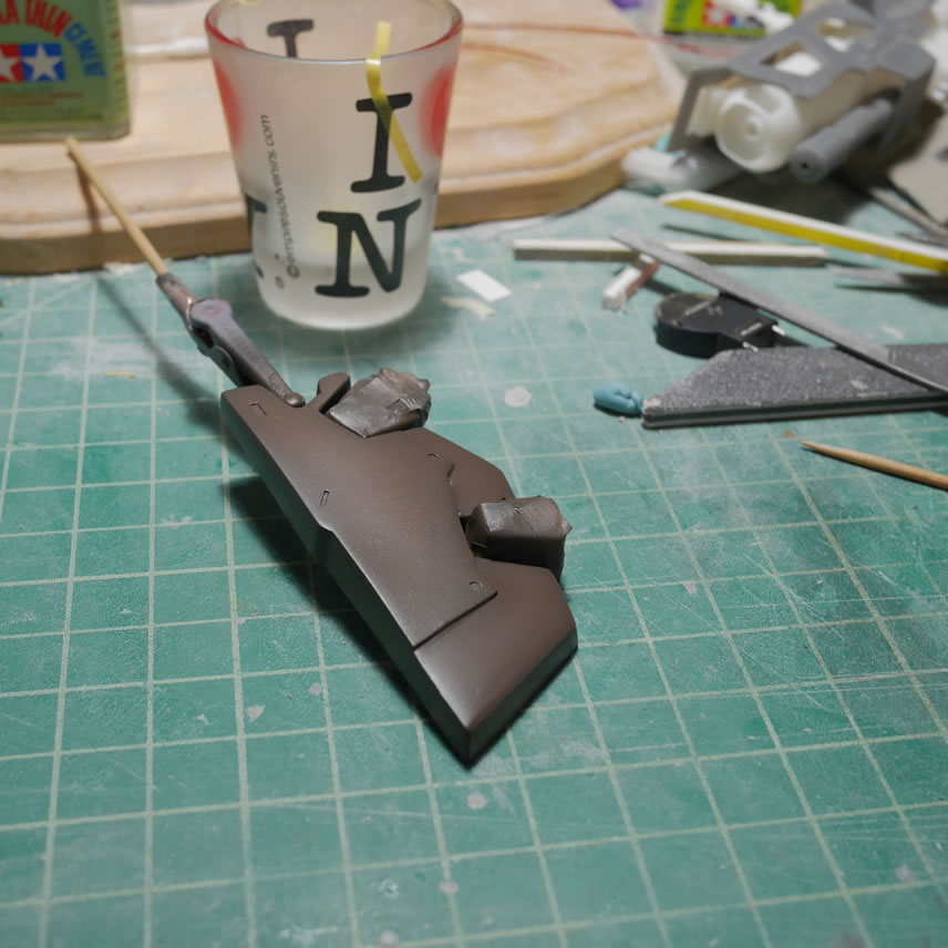
First priming session will show all the areas that need more work and attention. There are gaps to fill, some potholes, and areas to sand.

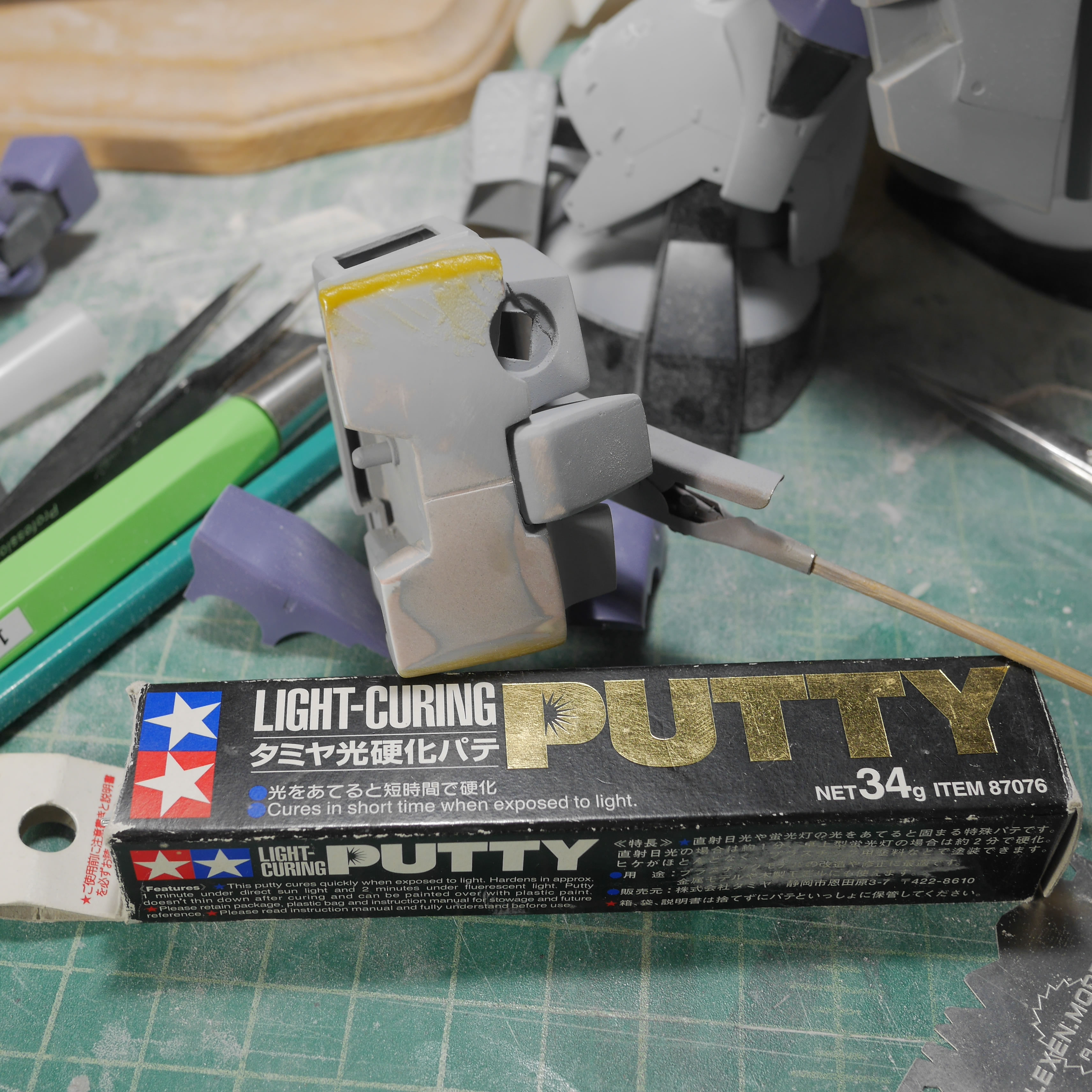
Light curing putty to the rescue. The gaps and potholes are filled with light curing putty and then everything is sanded down again . The primer really helps the process here since missed sanding areas will show up nicely and it is easier to the surface imperfections.
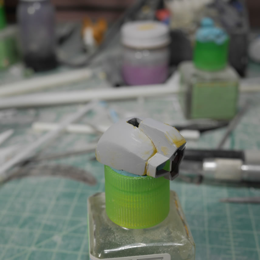
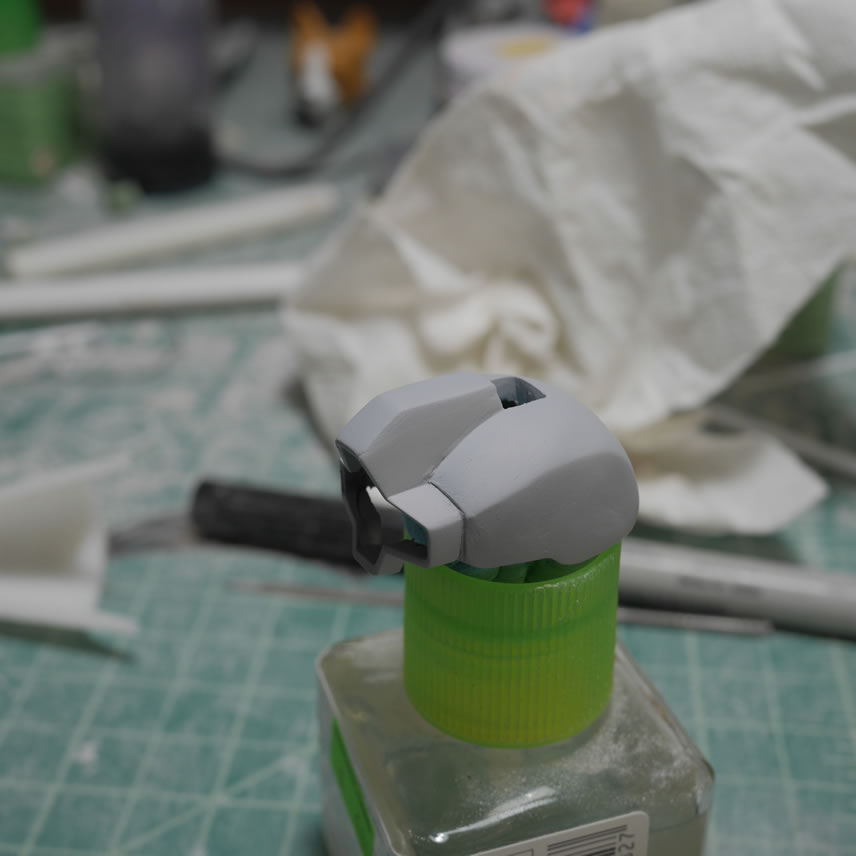
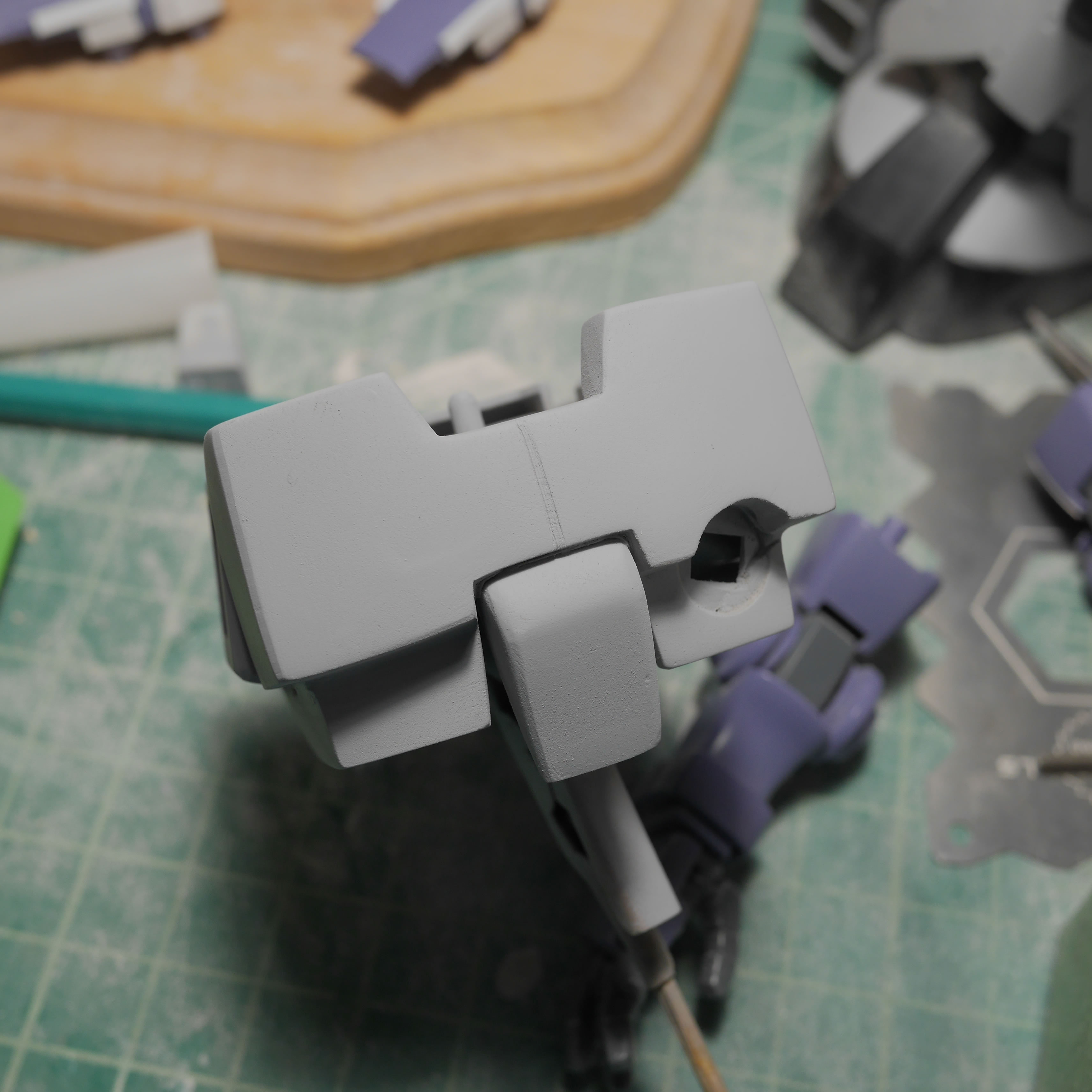
Another priming session and we’re ready for the next steps in detailing the head.
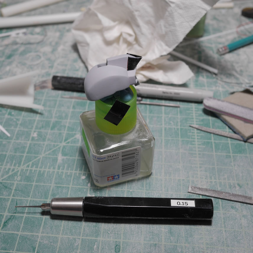
The thing to note is that there is an order of operation here. The major rework to the head needs to happen first and all the priming and sanding sessions to get the surface looking correct. After all this, we can get down to smaller surface details like scribing in new lines and such. If I started scribing in the small details first, they would end up getting lost in more putty or the sanding sessions. Dymo tape is used to create a few guides for the scribing tools. I also drilled out a small circle to drop in a metal detail piece.
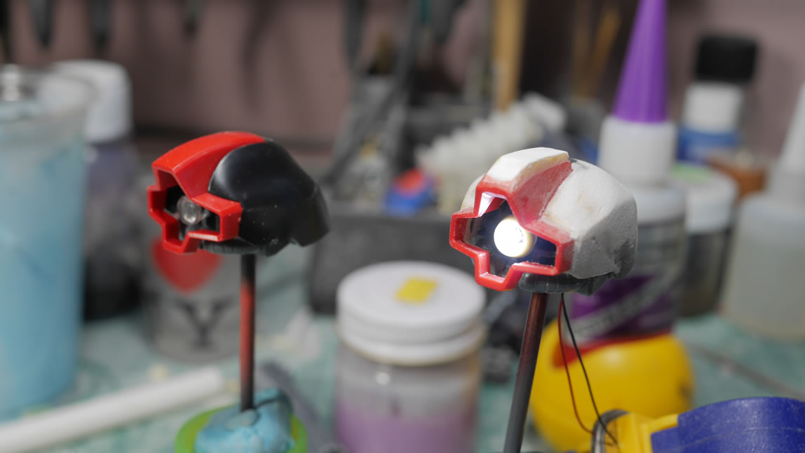
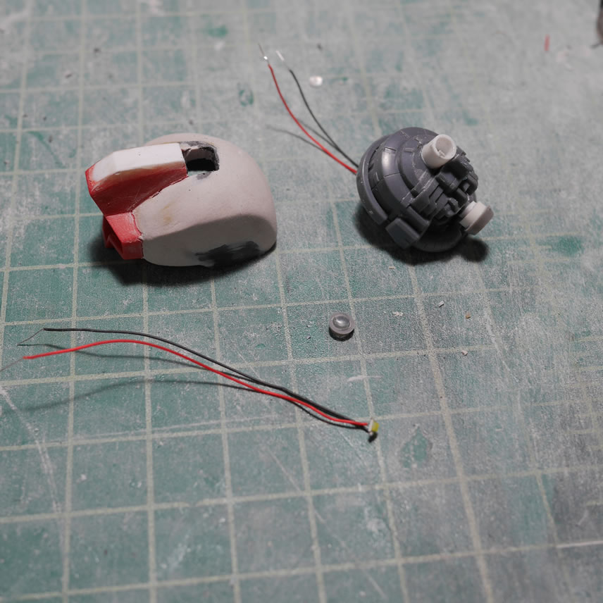
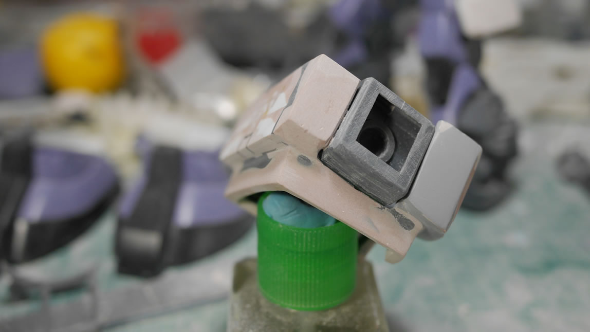
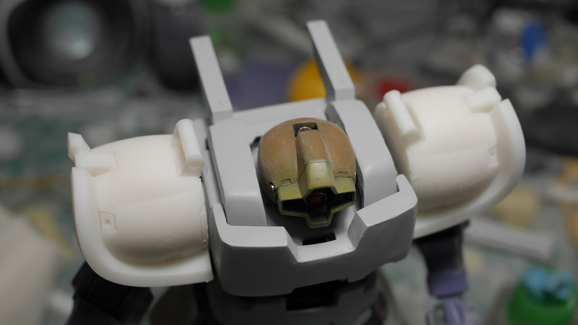
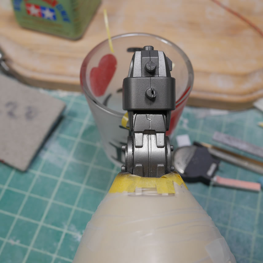
While all the above is happening, the internal parts are getting painted. THe main head internal is painted with alclad magnesium. The mono eye lense are painted with clear red on the edges to create a pink ring when lighted up. I also wired up the two LEDs in parallel and have one set of wires coming out of the bottom of the head.
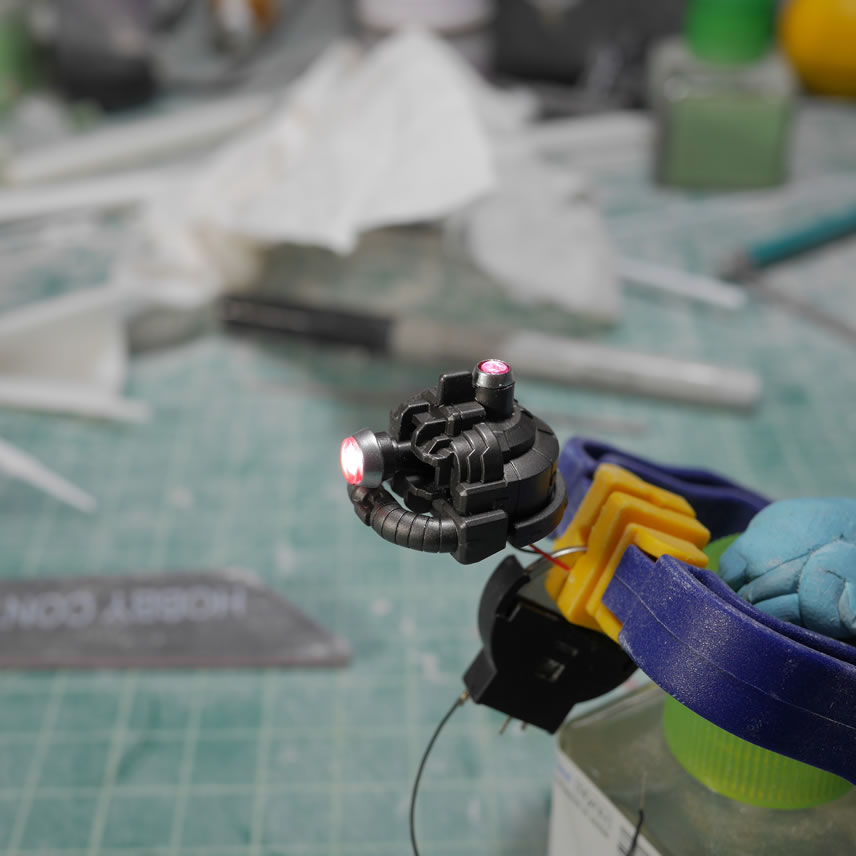
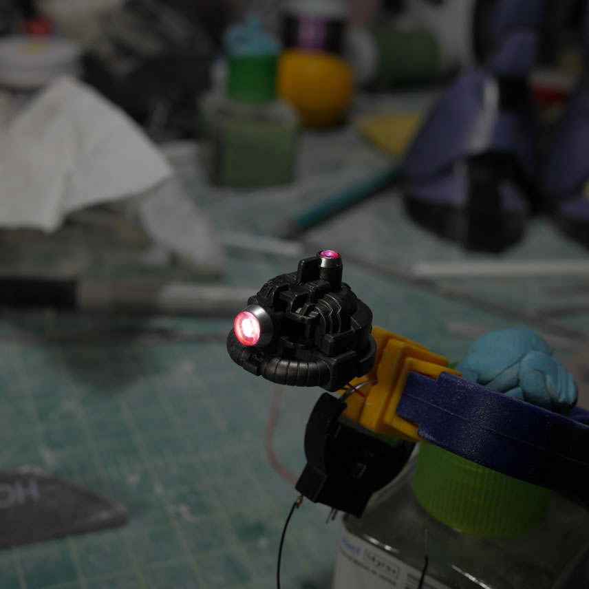
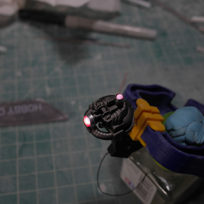
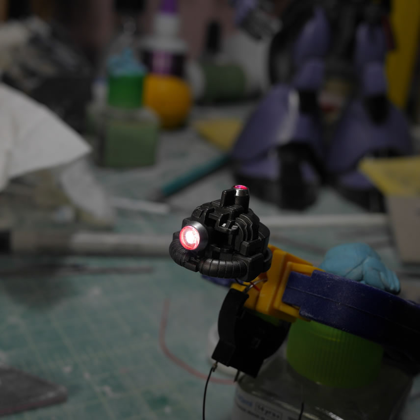
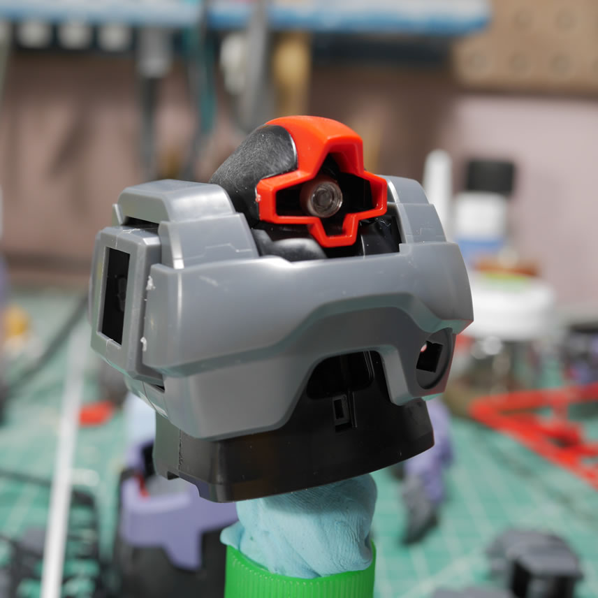
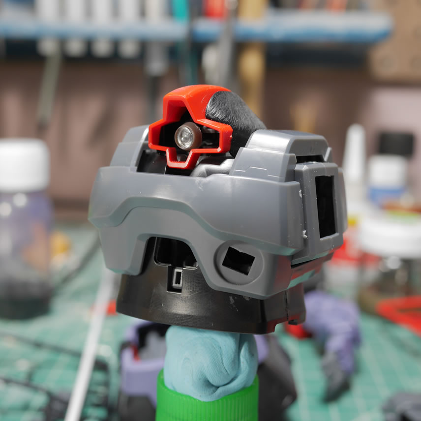
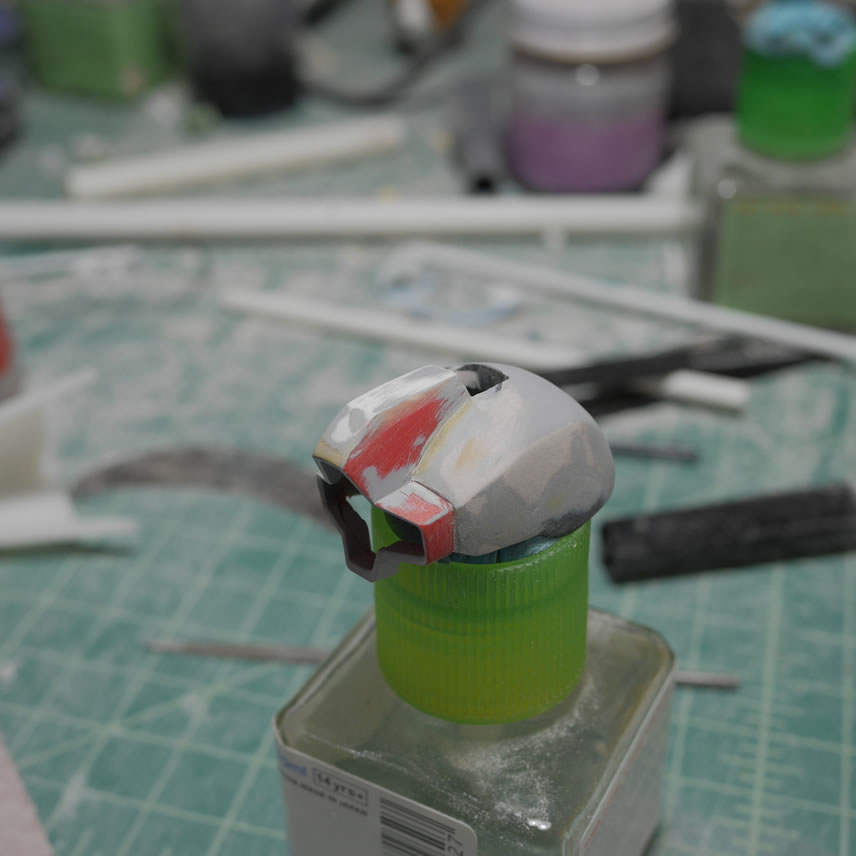
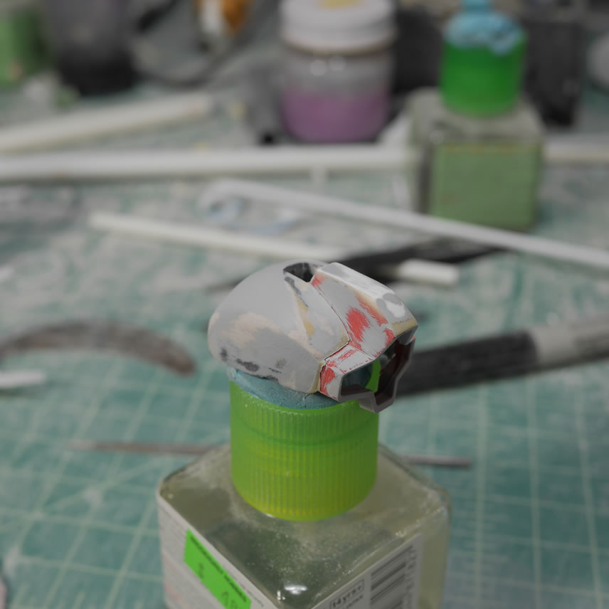
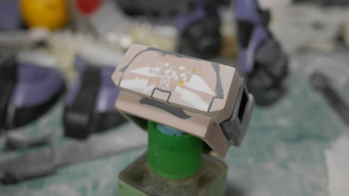
The head is painted with the standard Dom Barrage color scheme. Or what I see as the standard desert themed scheme. Using the dehydrator, I’m able to speed up the work time by several orders so I effectively did all the paint work in one day. Masking and painting, the head armor is almost complete.
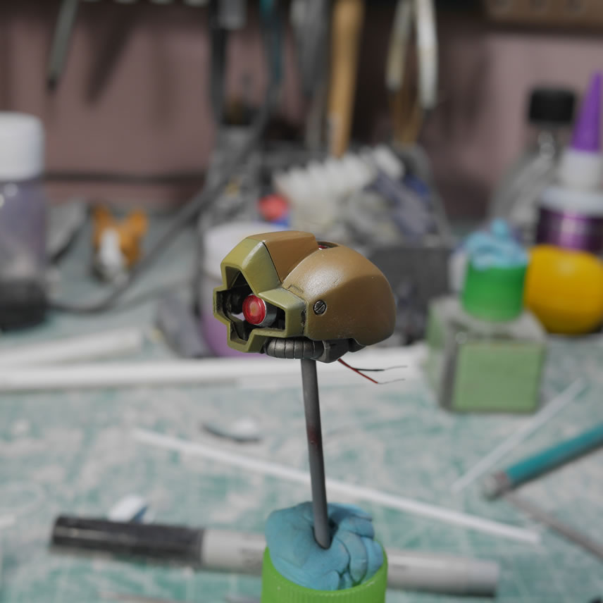
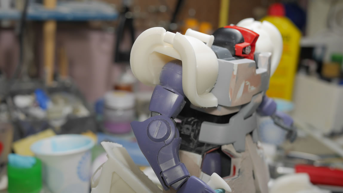
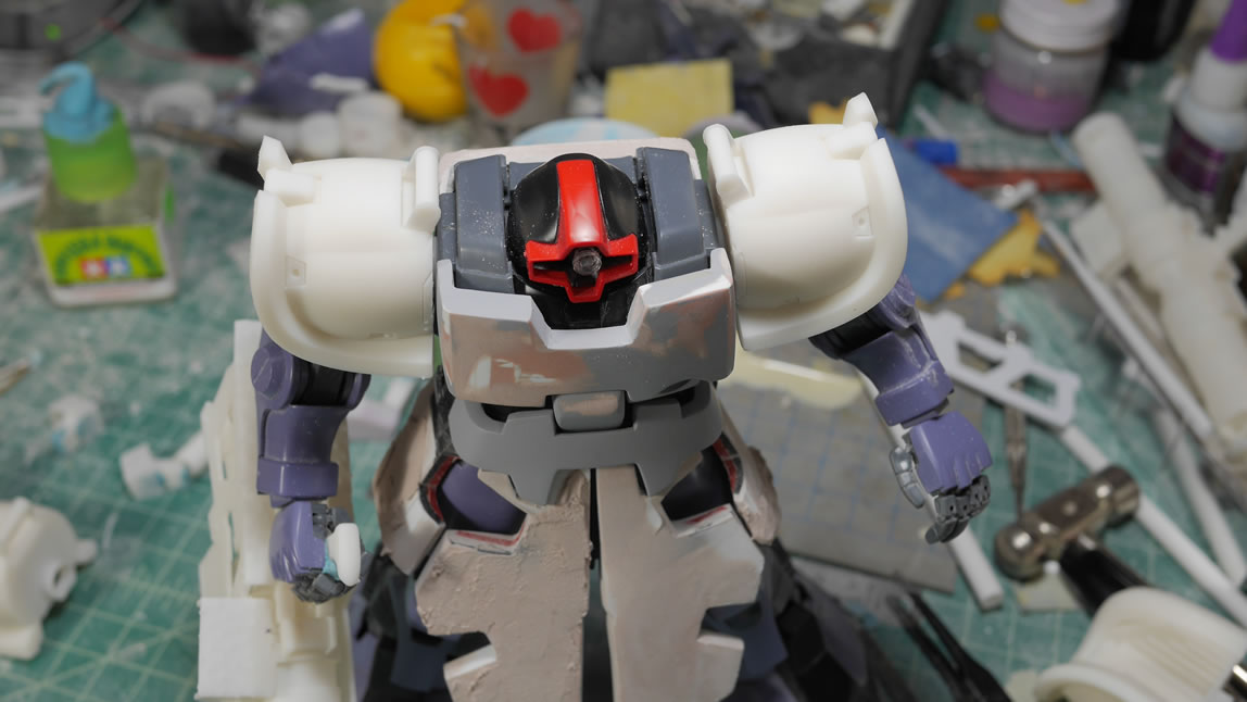
Assembling everything together I have an almost completed head. There are still some rough spots but I wanted to feel like something got accomplished. I will probably go back and fix some issues with the head while I continue to work on the rest of the kit. There is a sense of accomplishment with a small part of the project this close to being done.
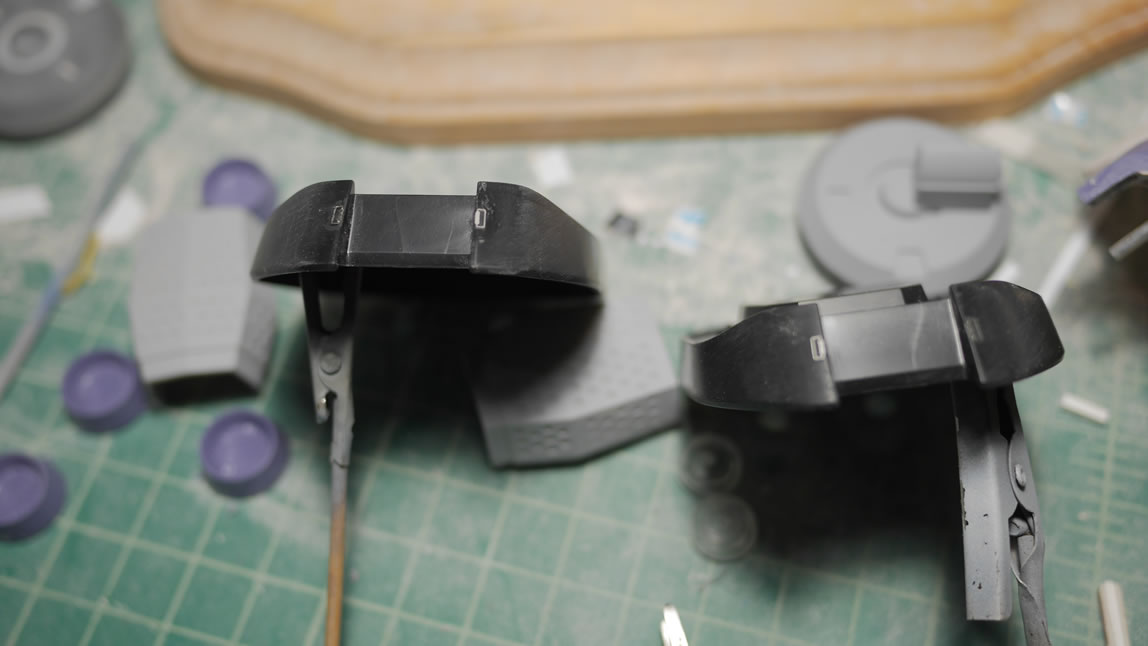
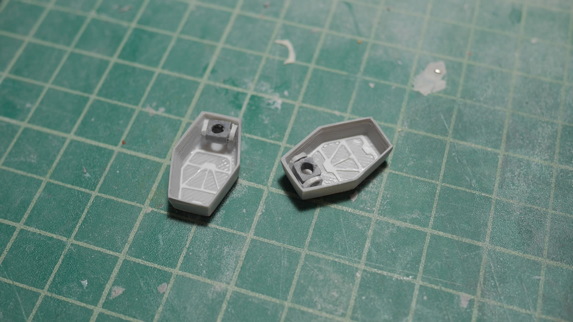
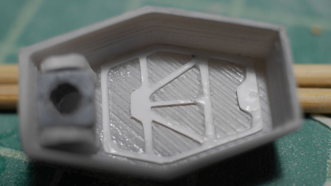
Returning back to the skirts, the bottom of the plastic sheet for the skirt needs some structure or the putty has nothing to stick and hold on to while it cures. Stripes of styrene are cut and glued into place. I also 3D designed and printed a prototype for the rear thruster engine covers for the skirt. The rough look is there, and like everything else in this project, a huge amount of refinement is in store.
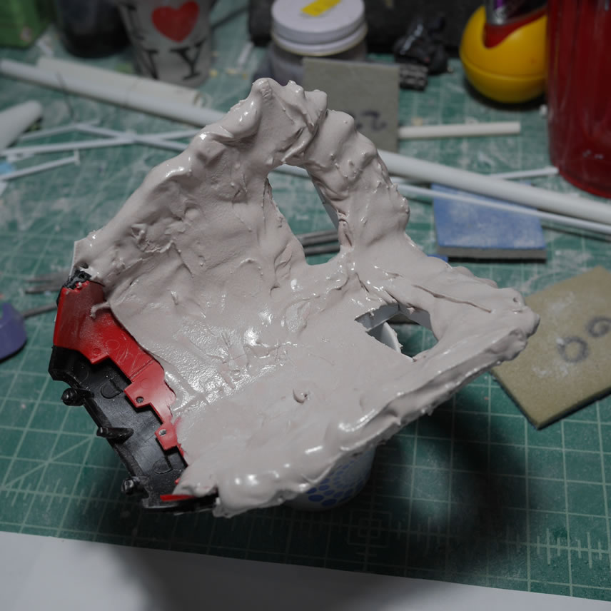
Since the plastic skirt piece was printed on a flat sheet of styrene, it wanted to stay flat. When I applied the polyester putty, I also put the whole assembly into a vice to bend the sheet while the putty cured which would result in a more curved piece.
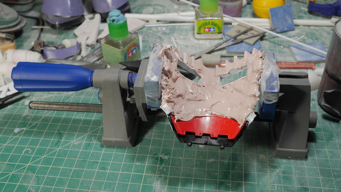
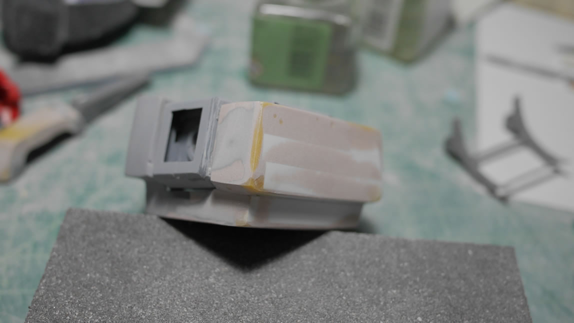
And then a more curved piece I got. I applied another layer of putty to continue the build up for the part.
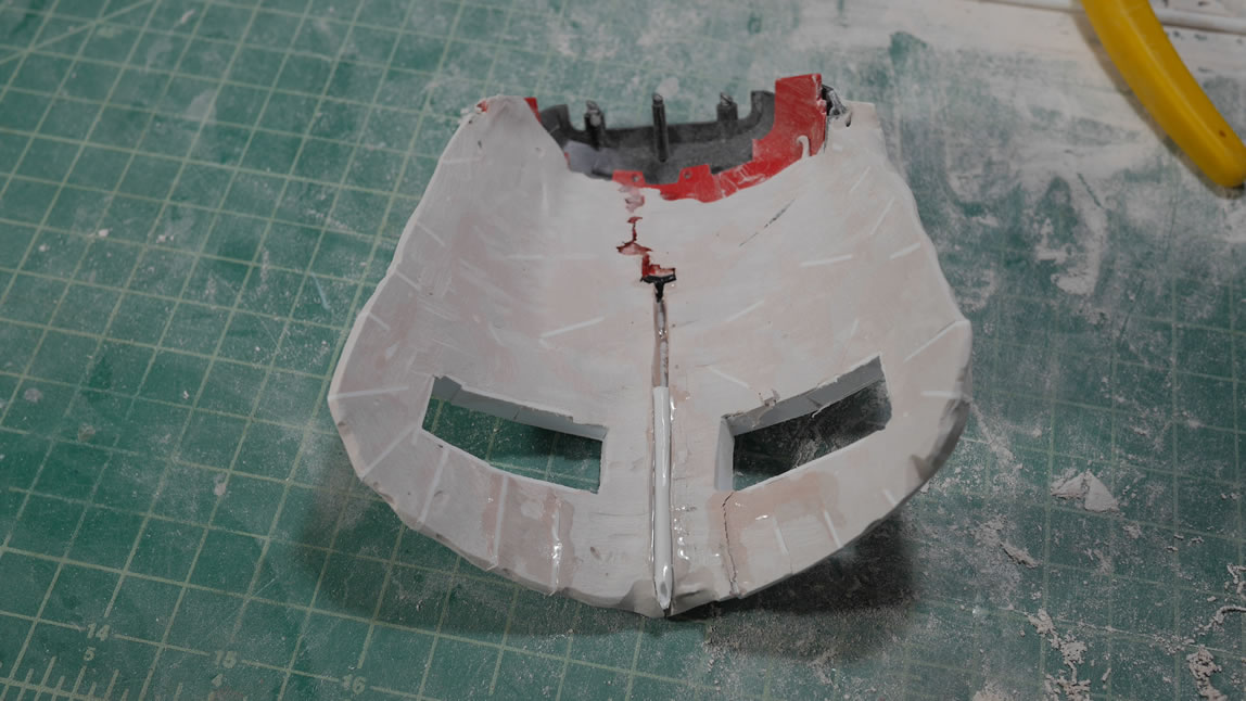
After some test fits, I found that the part was too curved. So in bending the part to uncurve it, the putty breaks and I have a area where I can add in some styrene rod as a structure to hold the part while I add more putty and basically adjust the shape of the rear skirt.
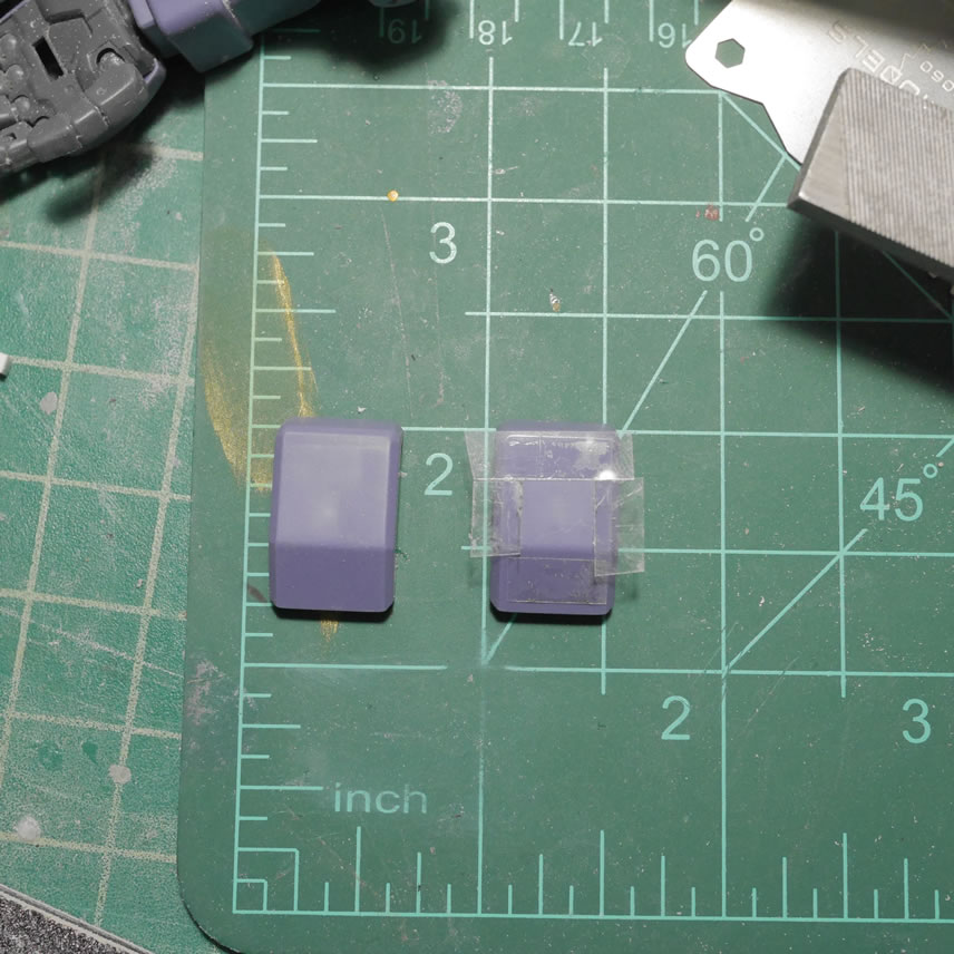
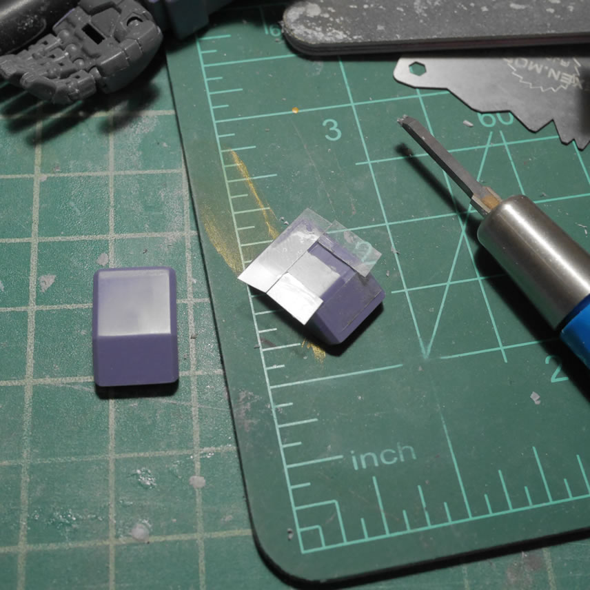
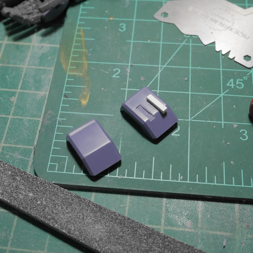
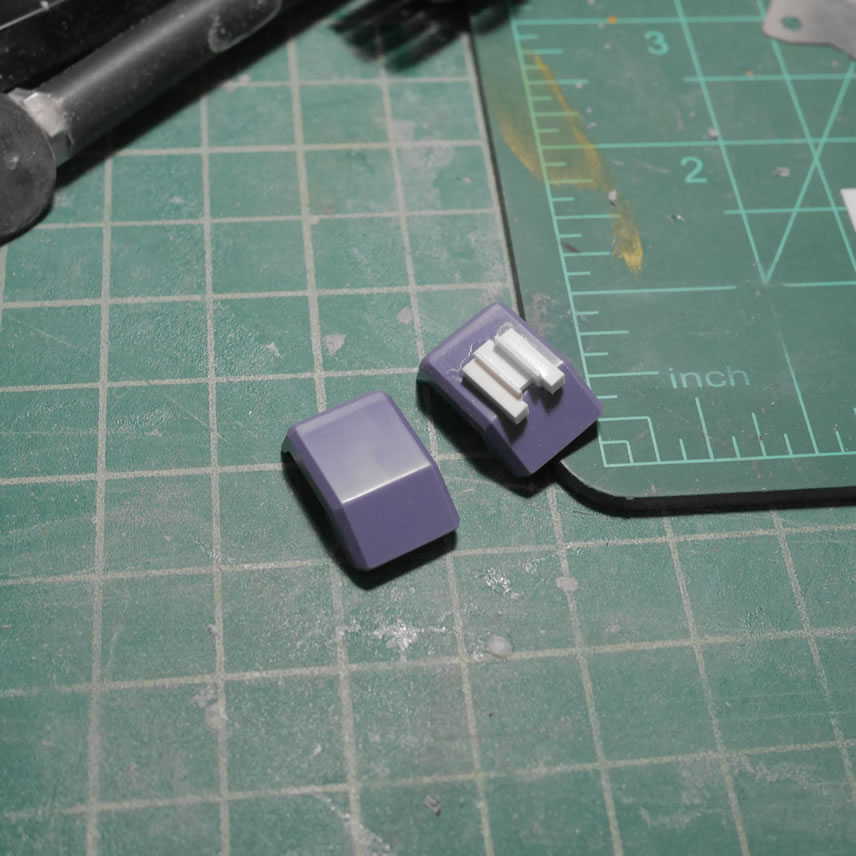
While the above is curing, I get to work on the Dom’s rear belt piece. Reference pictures show that there is a cut in the part so after some measurements, some dymo tape is dropped and I go to work on removing the excess plastic. With most plastic removal processes, I drill out pilot holes and then cut the excess plastic and sand down the edges to get the finish I want.
A quick test of the belt over the rear skirt piece. From the reference pictures, the cutout are where the tops of the thruster engine covers go, so that design makes sense.
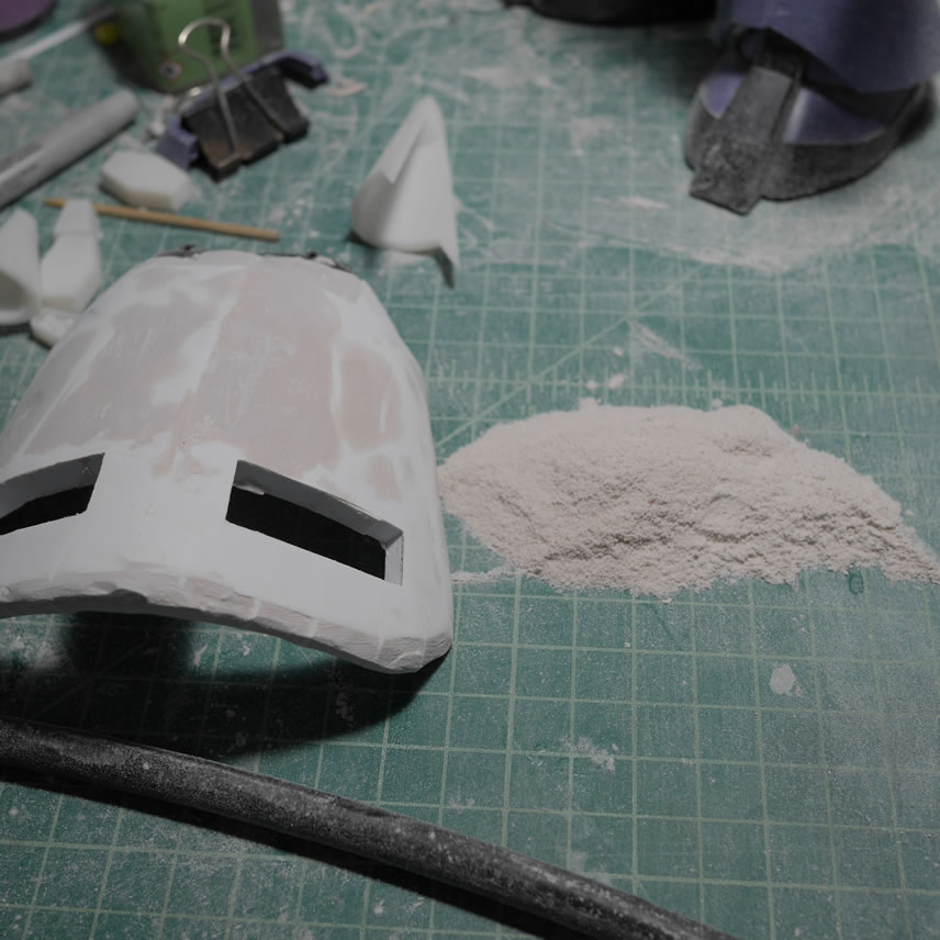
Sanding, sanding, and more sanding results in a pile of plastic dust.
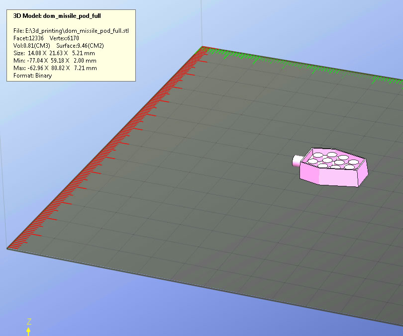
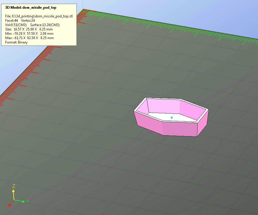
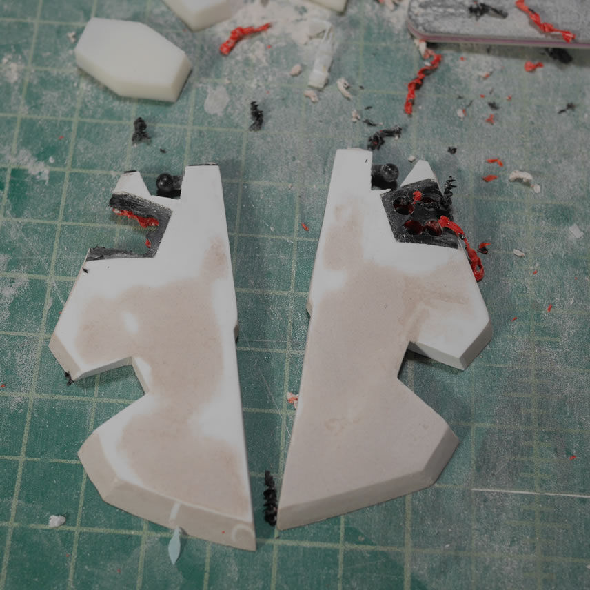
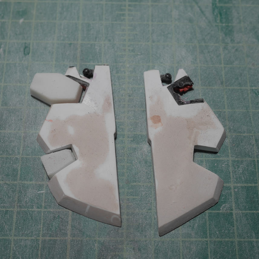
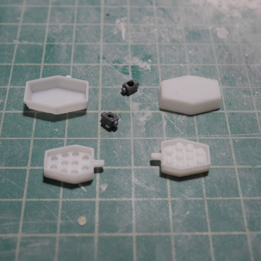
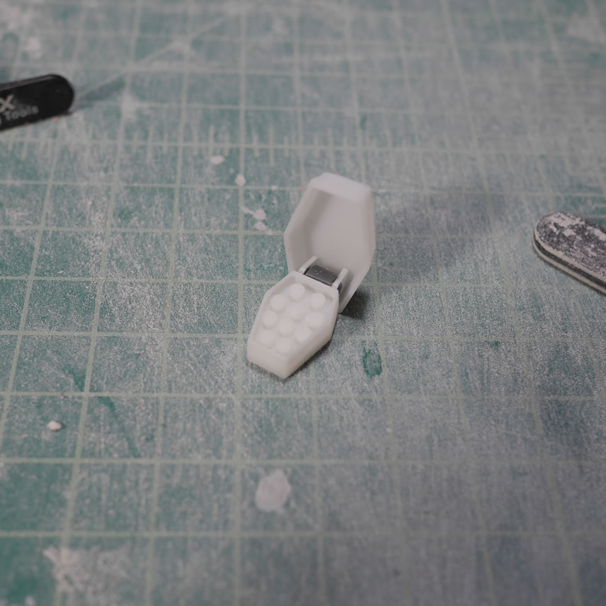
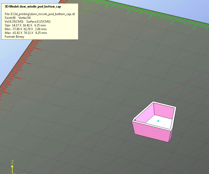
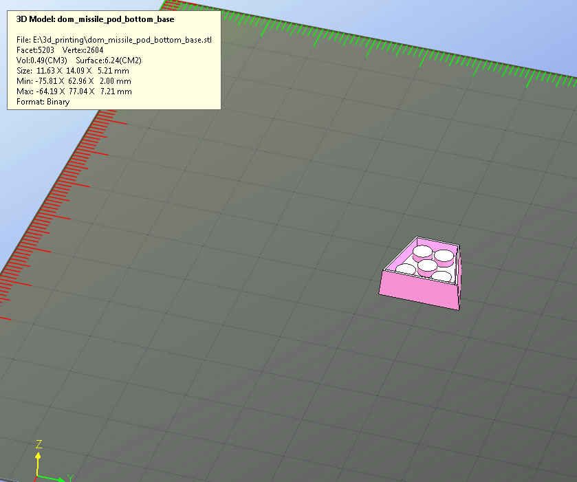
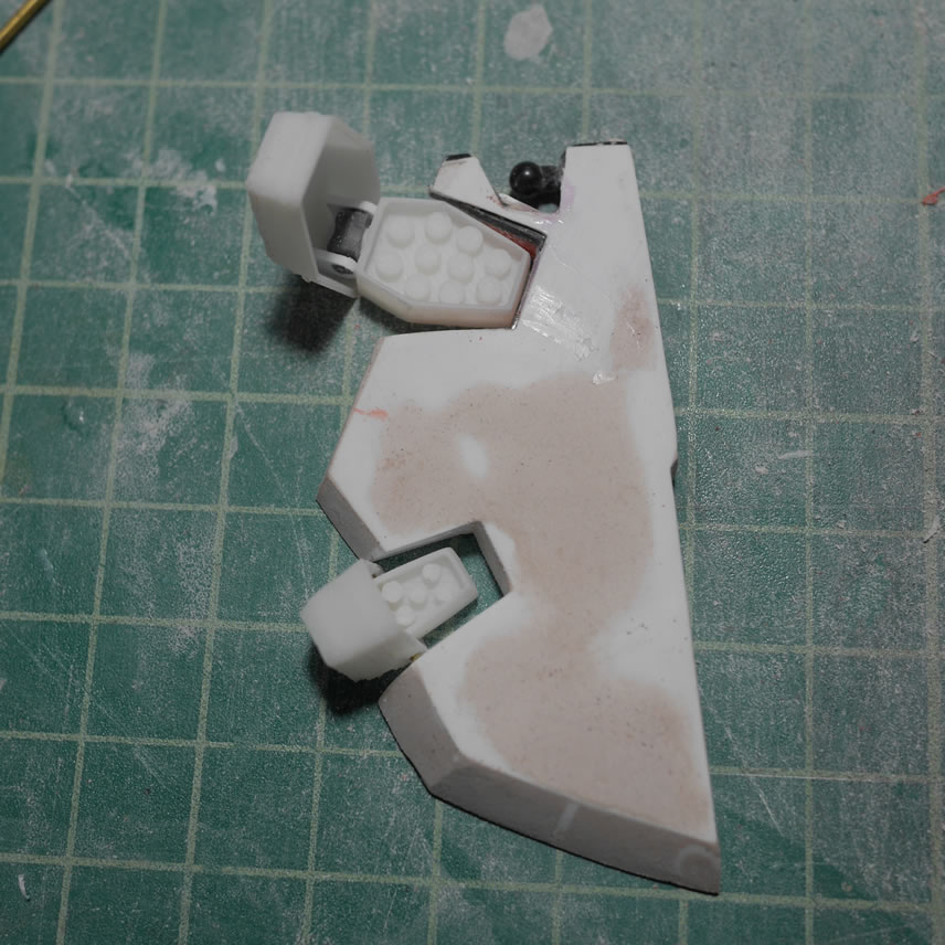
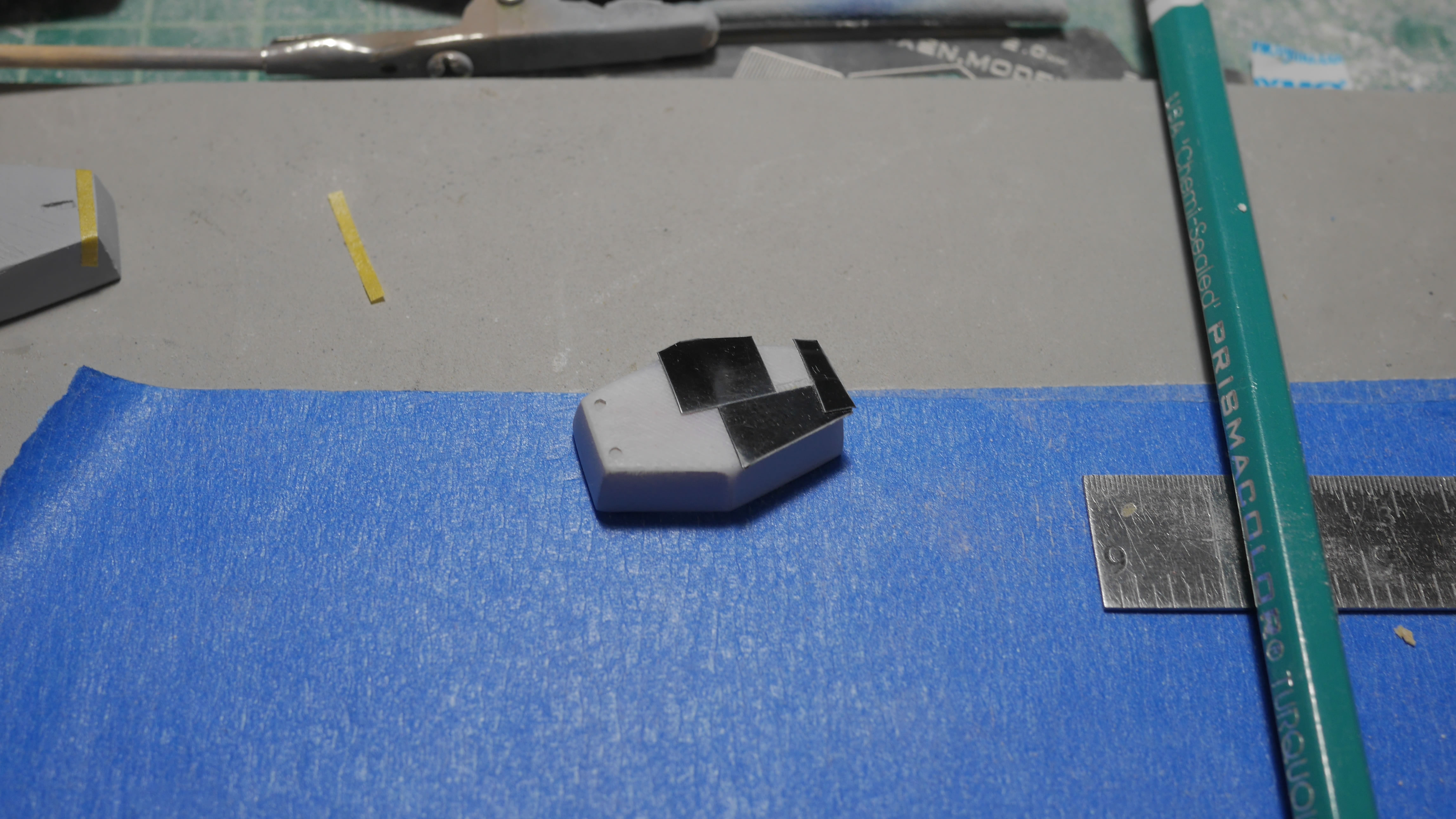
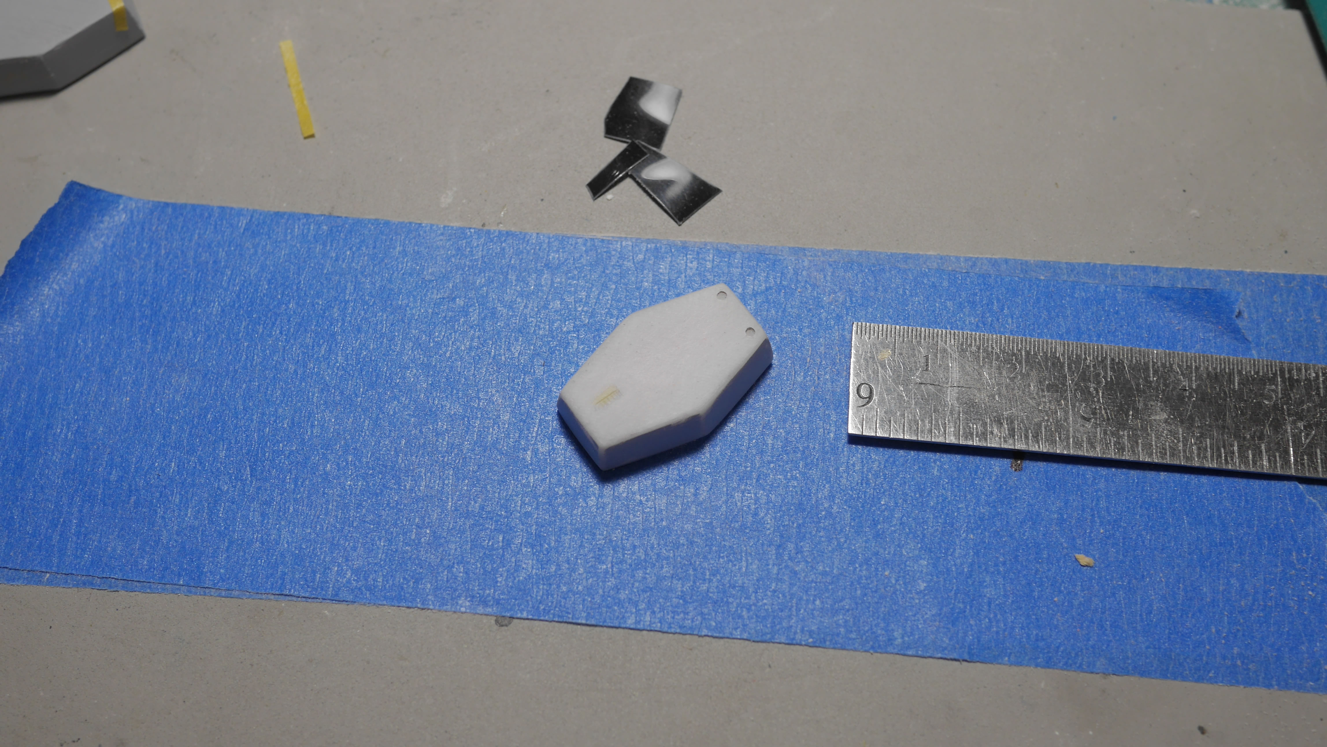
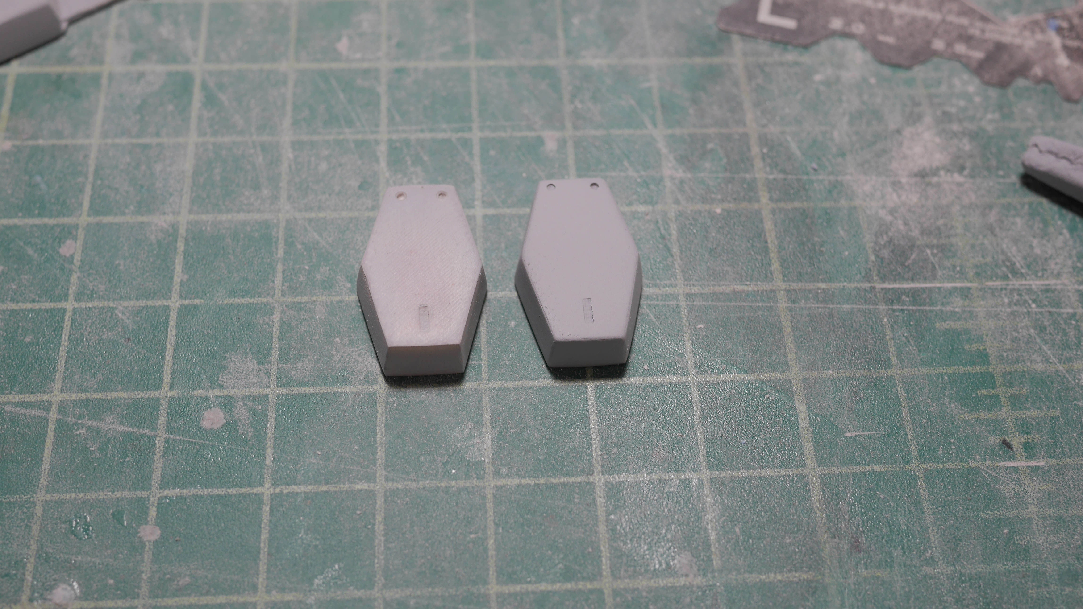
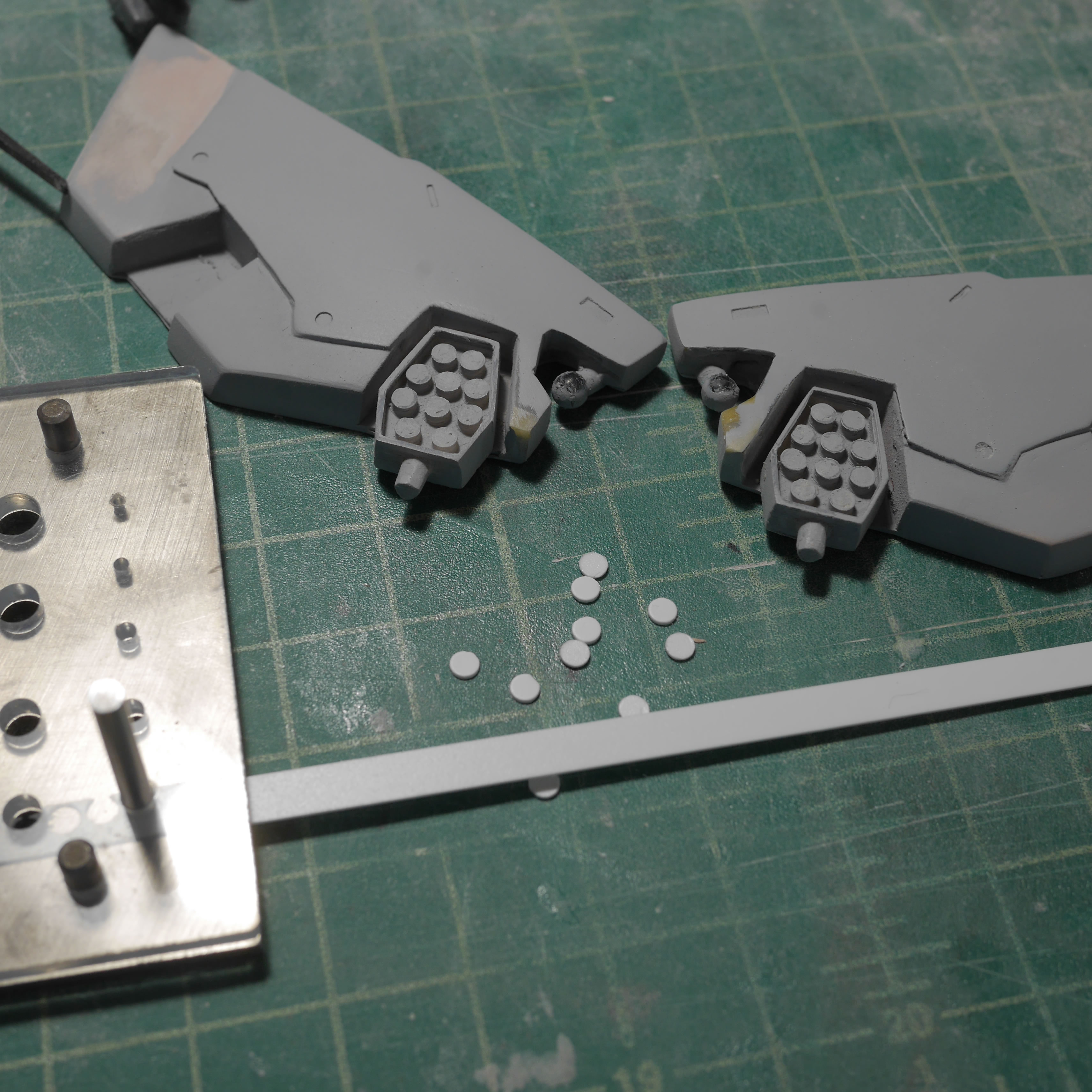
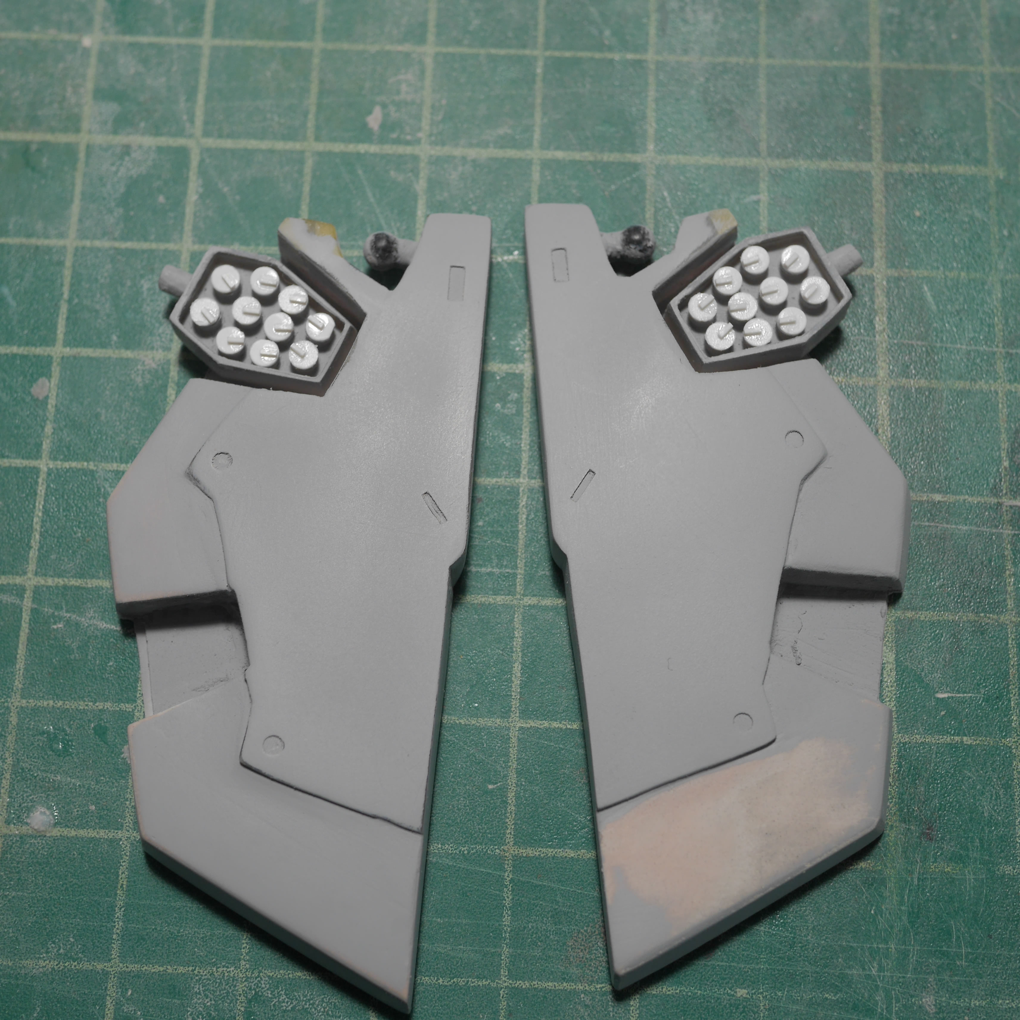
Returning to the front skirts, I go back to Blender and design the rocket pods that go into the front skirt pieces. Since I’m going to try to have them openable, I designed the cap piece first, then from that cut it out and worked out the base piece. I also designed it with and without rockets. I figured I could make the missiles from styrene tubes and paint them separately. But I think the pod with rockets will probably be easier to work with since I don’t have to fill and sand as much for the pod without rockets. Below are the STL files for the rockets; clock on the images for the STL file download. I used larger pictures so you can see the size reference I used when I scaled these prints out for the Dom.
![]()
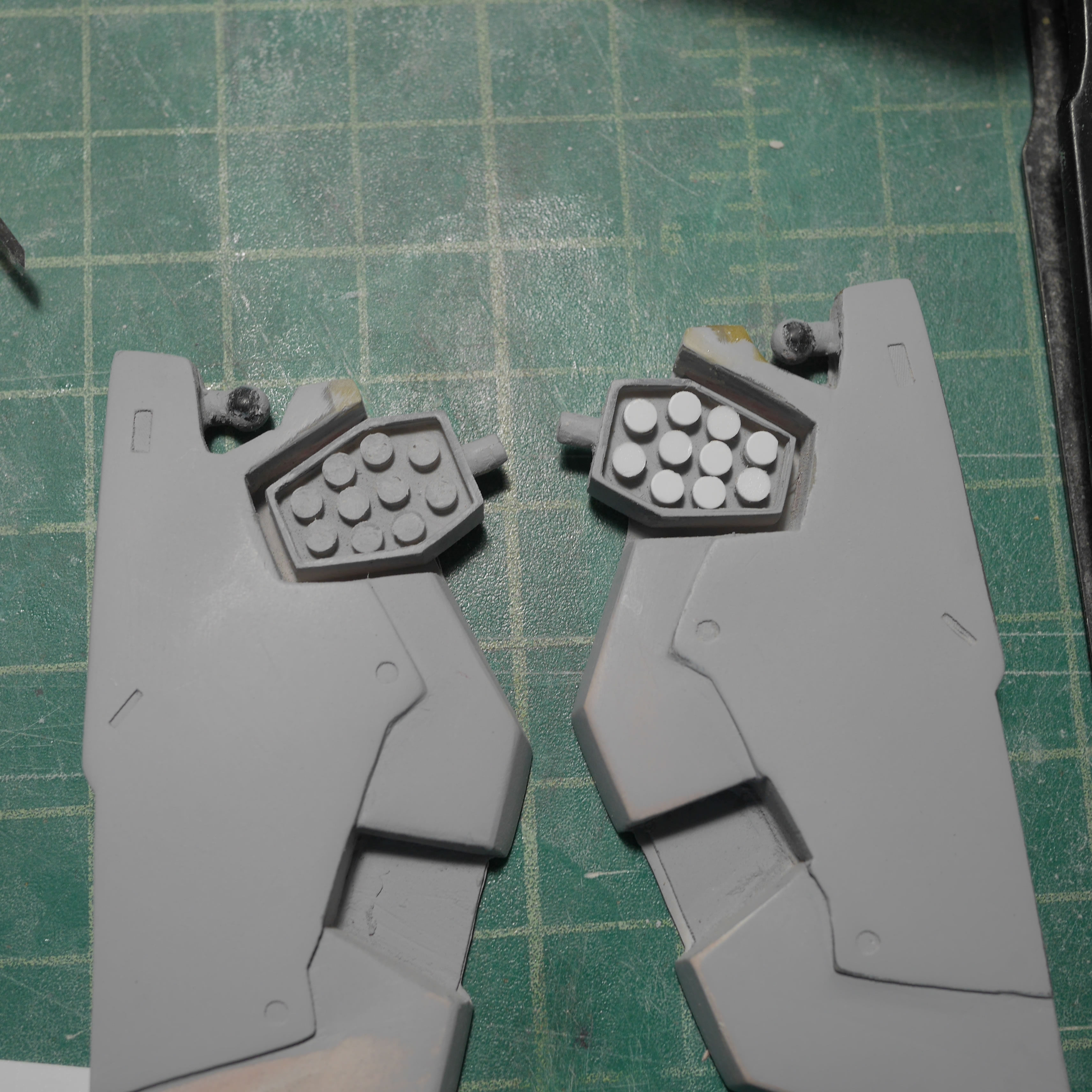
Here are what the pods look like just tacked onto the skirt. I used sticky tac to hold everything in place as well as display the pods opened and closed.
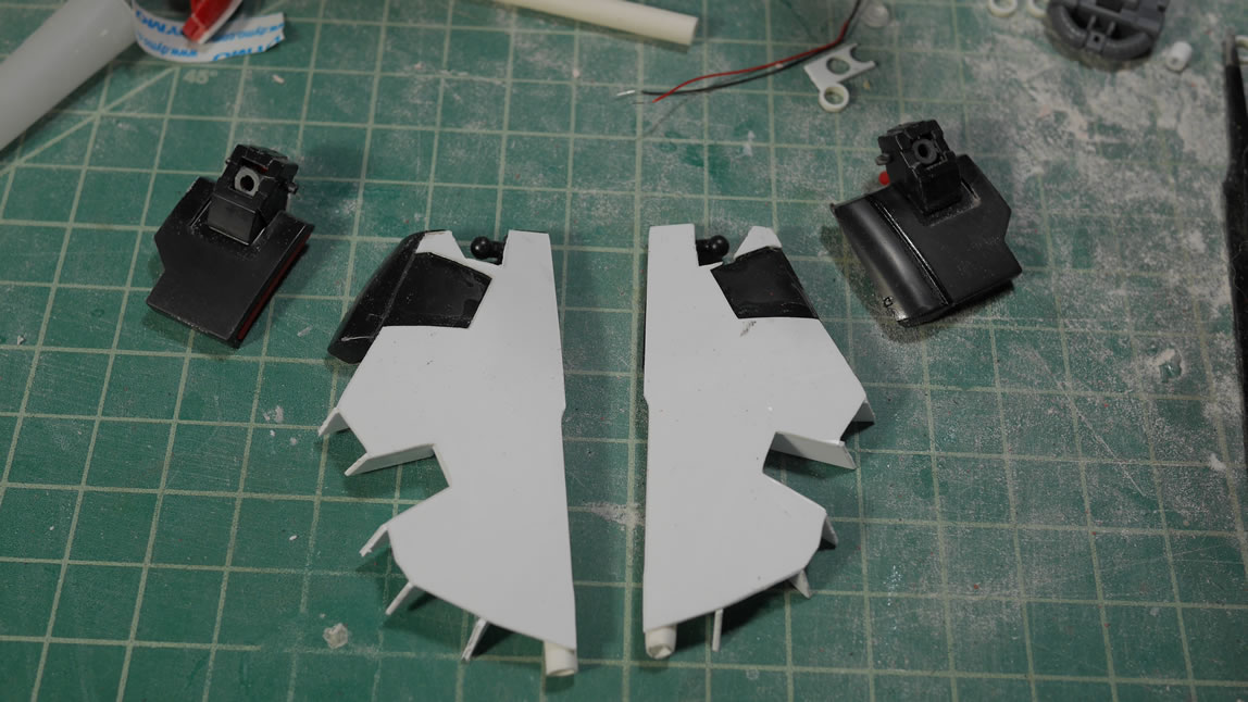
I will need to cut out the skirt pieces to fit the pods into place. So that work on the front skirts started with drilling out pilot holes and then sanding. The upper edges of the skirt are very thin once this area is cut, so I reinforced this area with strips of styrene glued into the two halves of the Dom’s original front skirt parts. I also have a quick mockup with the lower small rocket pod.
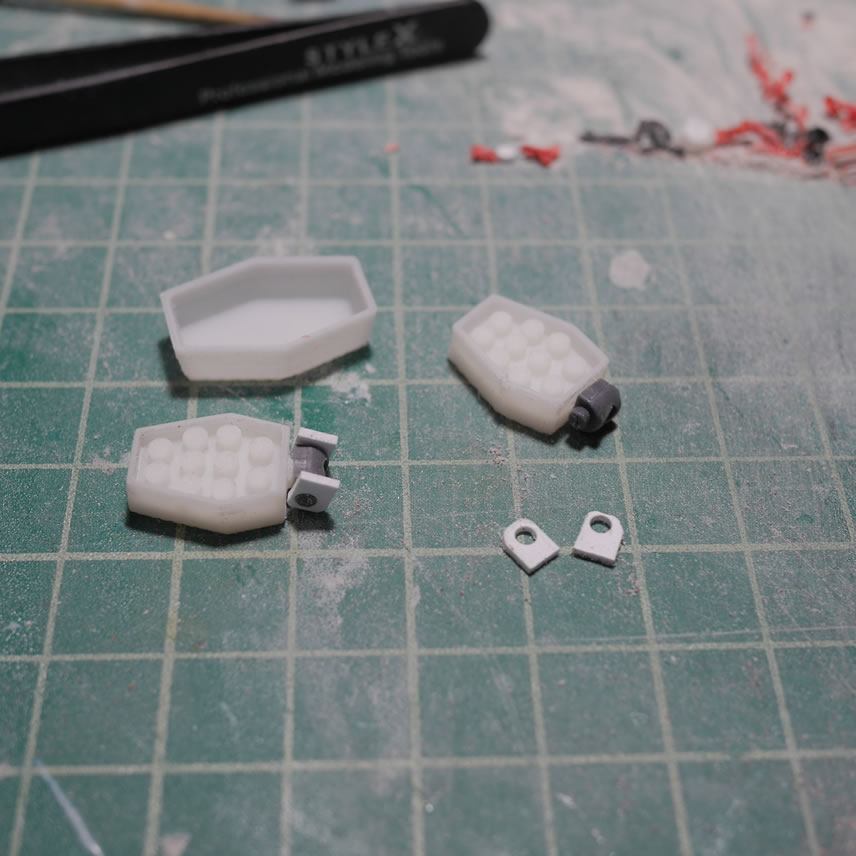
I designed the opper pods to be openable with a polycap, so a few stripes of styrene cut to size and a hole punched to fit the poly cap and I have a hinge piece. A fairly large hinge piece mind you. I will have to design something completely different for the lower skirt pods as they are much smaller than these pods.
Since I’m posting up the STL files for this project, here are the files for the lower skirt pods.
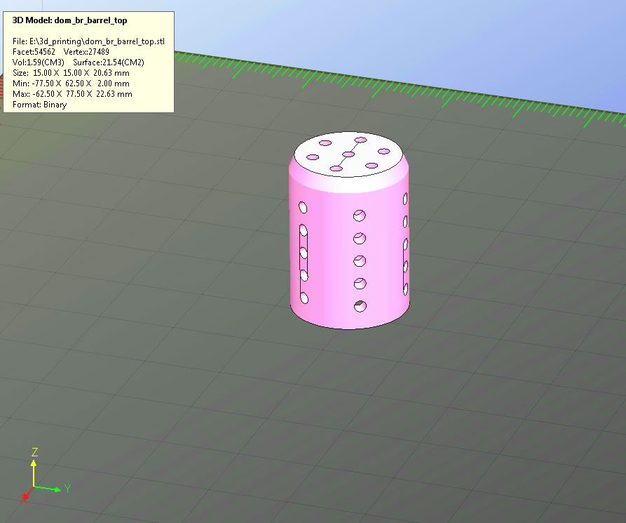
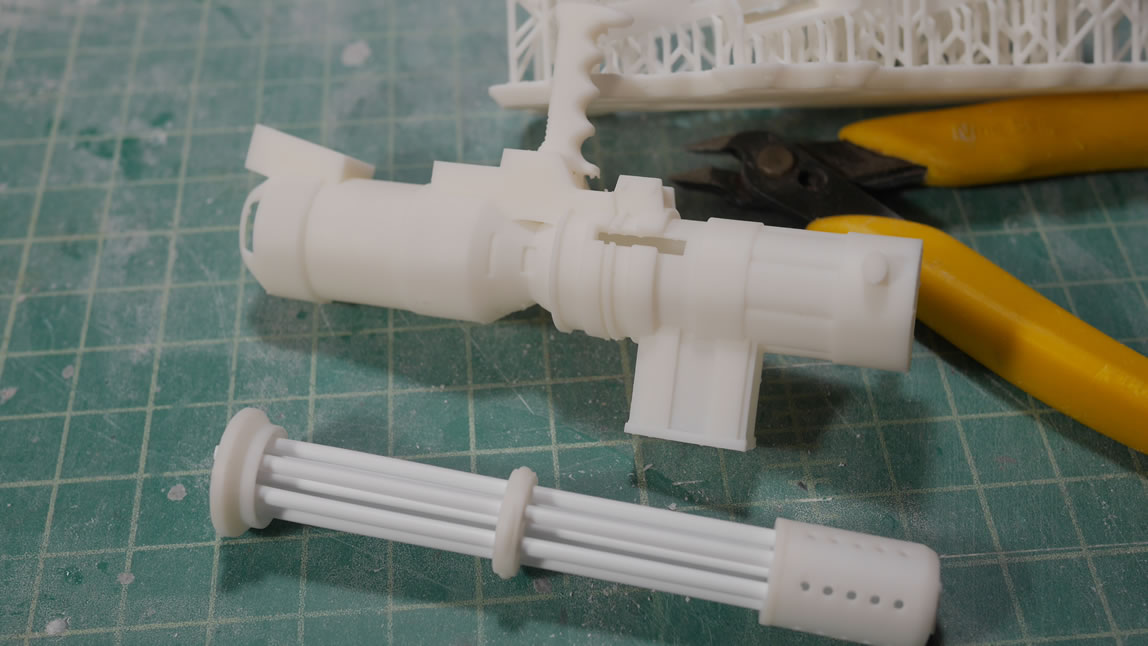
Here are the three pieces for the gatling gun front. They include the barrel, the center support and the barrel base piece. Styrene tubes thread through these to complete the front section of the gatling gun.
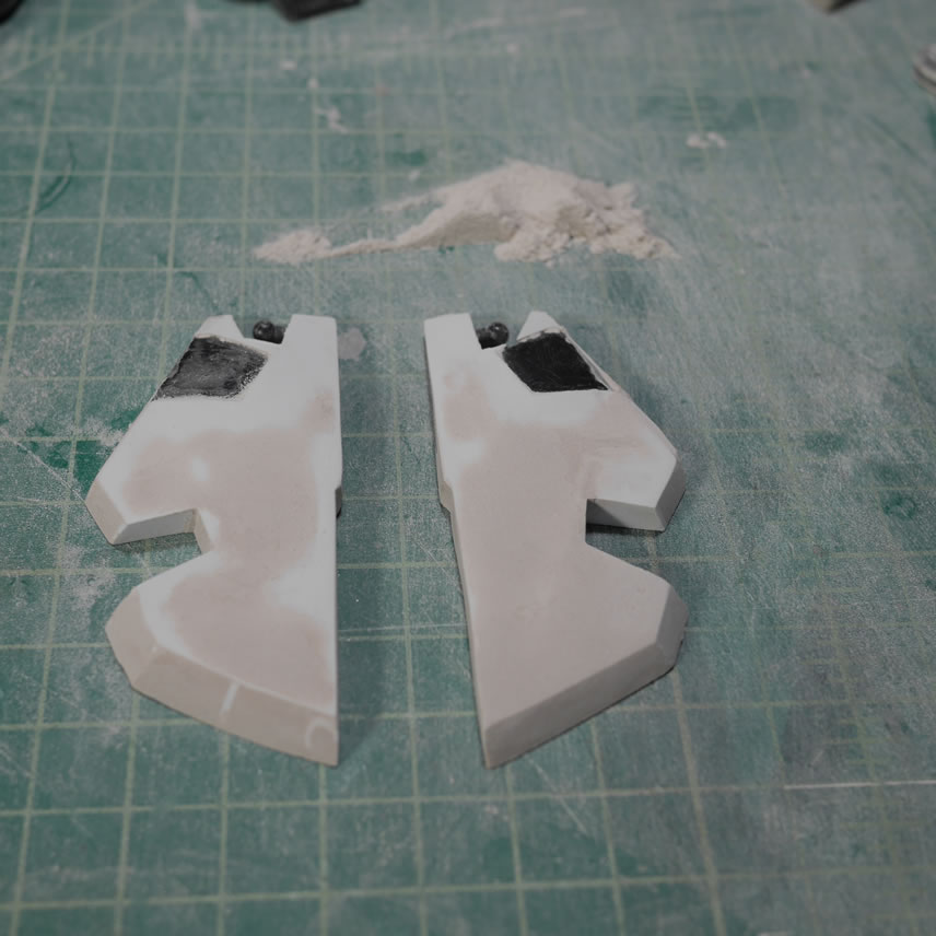
March 27, 2019: And now back to our regularly scheduled programming. It has been a decent while since the last update for the Dom. I got interrupted by the Exceed RX-78 thingy as well as a shiny new Form 2 3D printer. The latter bit ties in nicely with this update. Continuing from where I last left off sometime last month; I was still cleaning up the work on the front skirt. I had FDM printed the missile pods and created them so that they can be opened. The skirts were cut and sanded so that the pods can be inserted. Here are a few test pictures. You should be able to see that the two skirts are not identical and will need more work. The area for the lower small pods is a little off too, so more putty work is in store for these parts.
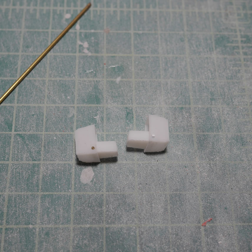
As with the larger missile pods, I made the smaller missile pods in two pieces so that I can display the pods opened or closed. Since the smaller pods have less room to work with such that I cannot install a polycap system. I redesigned the print to have a hole through the two pieces that I can insert a brass rod. Now it’s openable.
Since the front skirts are in pretty good shape, I can start working on the side skirts. I cut into the side skirt (the area I had originally cut from the original front skirt piece and glued to the side skirts) to allow for the bigger missle pods to fit. Test fitting as I go, the area is filed down and more plastic is glued on to align the bottom of the side skirts with the new front skirts.
Once the side skirts were cut, styrene is glued into place on the front as well as on the back with supports (for the polyester putty to stick). Then the skirts are puttied and sanded to resculpt the shape. The process is pretty simple, but fairly labor intensive and a test in patience for things to cure.
Always test fit. Never build assuming things will fit. Bandai spoils us horribly. Whenever we go outside the kit’s original design, things go south pretty quickly if you’re not constantly measuring and test fitting. The pods are test fit and opened to make sure everything still works and there is room for the pod’s opening functions. The test fitting continues through priming just to ensure the clearances are correct.
I marked the front skirts to help with the additional putty work. With the pods for measuring, I can now get the final shape of the skirts down. I am doing nothing but adding more putty, then sanding and more test fitting.
The rear skirt gets a few rounds of sanding and test fitting as well. The rear skirt is starting to getting pretty heavy. I think the polyester putty may actually be heavier than a solid resin block.
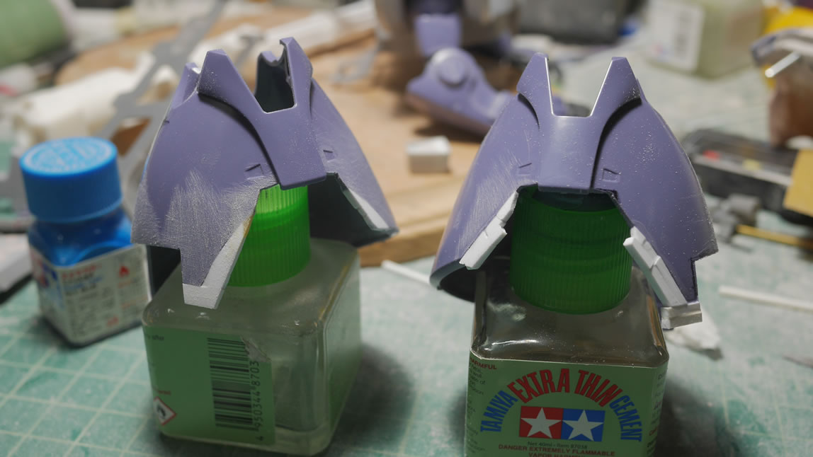
It has been a good couple of minutes since I last posted and these pictures are at least a month old. It is hard to remember what I did without the notes that I write while things are still fresh. But I’m guessing that I did more test fits and more sanding. The front chest piece is coming together. The shoulders are getting some putty work, but I’m seriously slowing down and avoiding the shoulder work because I am seeing the same issues I will have as I did with the front skirts. Symmetry. The skirts are coming along and you should be able to see a difference in the shape in these pictures compared to earlier in this post. The transition between the lower pods and skirt is more uniform and show makes a little more sense with the lines of the skirt.
As I sand and sand, I’m constantly cleaning the putty dust off the work area. Work was getting late into the night which then told me the Dom needed a little pick me up, so I gave him a styrene tube and cut some lines for him. *SSSNNNNOOOORRRTTT* Ok, we can get back to work.
Things look deceivenly smooth. A layer of primer will really show off the surface.
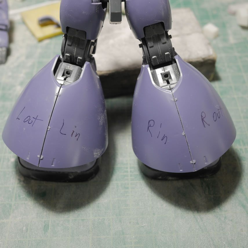
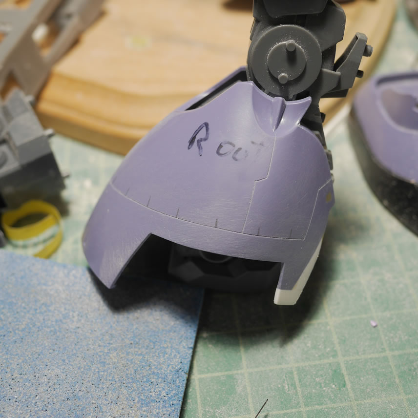
Taking a quick break from the skirts, I move down to the legs. I will need some surgery to the legs so first things first, mark off the parts of the legs and LABEL everything. I don’t want to be working on a specific axis for what I think is a particular section when it isn’t and completely F things all to hell. Lessons learned from previous modification projects. Permanent marker the crap out of things so that the part you are working on is the correct part. Some cutting is done and some styrene is glued into place and the legs are pushed to the project’s backlog and forgotten just as quickly.
This is about the time I got the Exceed RX-78. And a week after that, I got the Form 2 SLA 3D printer. So having done enough testing, I want to revisit the gatling gun that I had been working on using the FDM printer to help augment that build. My originally built gatling gun melted after I had placed the whole assembly into an acetone vapor bath for too long. I was using the vapor bath to help dissolve the resolution lines from the FDM printed parts. The side effect for vapor baths is the loss of sharp details. So if you were going for rounded parts, this works. If you want very sharp corners and details, avoid at all costs and just go with putty and sanding to fix the .15mm(highest level of resolution with the FDM printer) resolution lines.
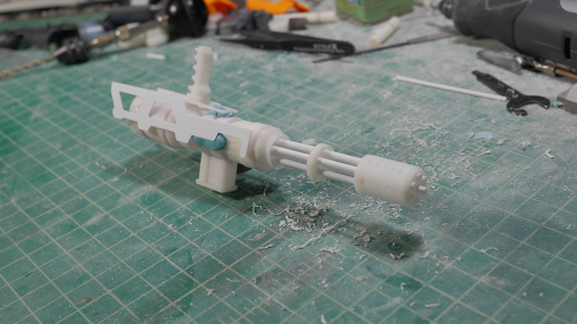
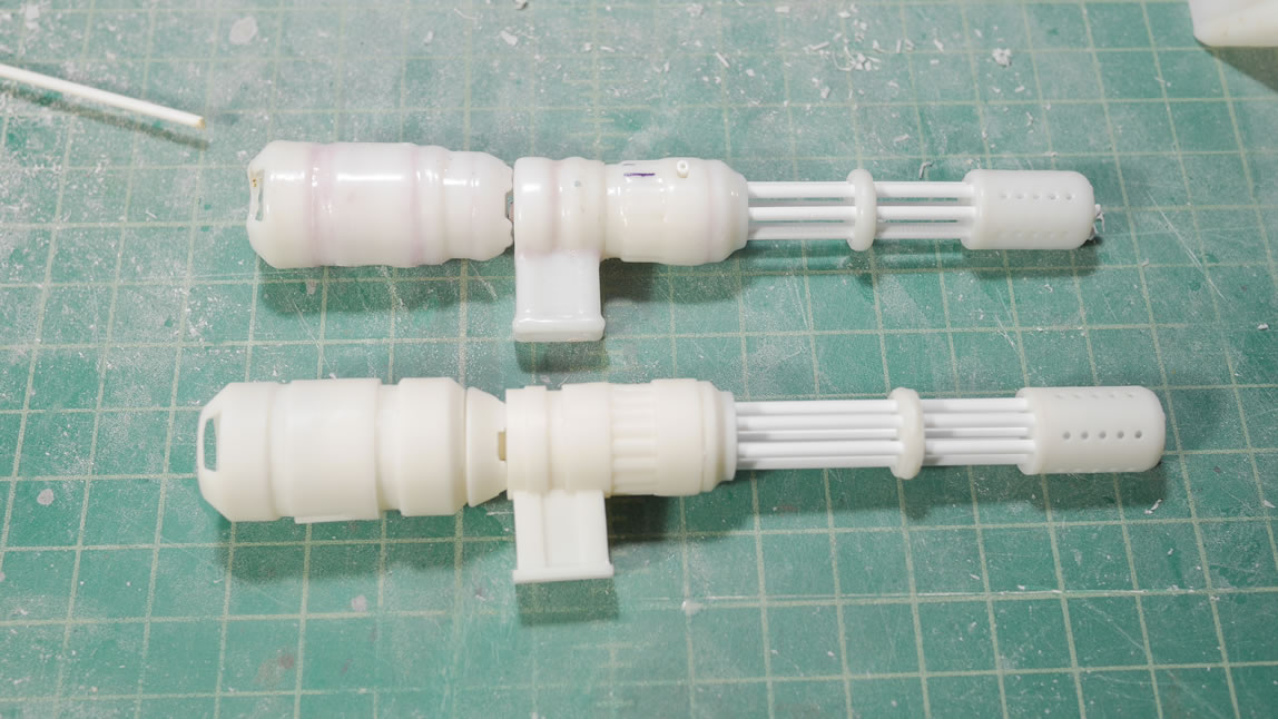
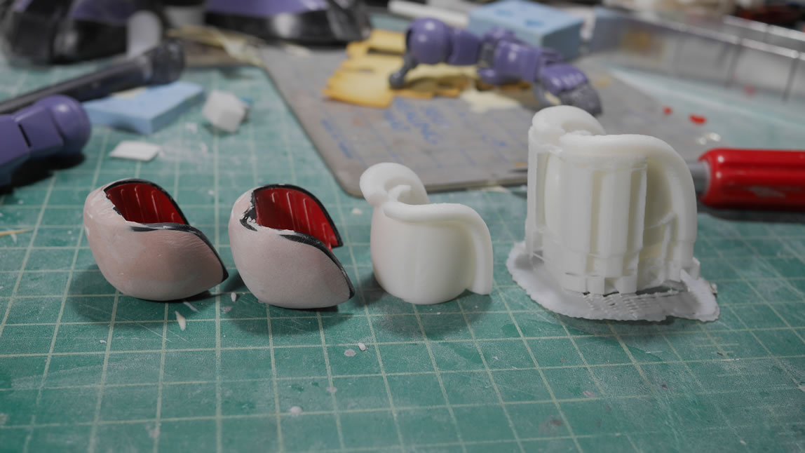
Since I melted the original gun. Time to build a new one using the same 3D files from the FDM print and print them out using the new Form 2. The results are not bad as seen in the comparison shots below. I can continue forward and start on the frame.
Originally, I had cut out styrene using the cricut die cutter and a drawing of the gatling gun’s frame from reference pictures. The lack of precision bothered me a little even after sanding, so since I had the Form 2 now, I can probably print the frame as a whole. I went back to blender and designed the frame from the ground up. Since that worked sorta worked out fairly well, I kept going and decided to redesign the main part of the gatling gun(for which I had already printed out with the first set of 3D files). I needed to check the size references with the newly designed frame with the main gun, so why not. Scrapping everything I did earlier for the main gun round pieces, I started from scratch and redesigned the main gun with what I had learned all the new techniques I learned thus far. The ejection port was redone as well as the ammo feed port. I mocked up the barrels so that I could get a better proportional view of the whole gun. The actual barrels will be styrene tubes, but everything else is 3D printed.
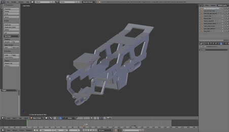

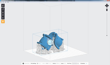
I spent a few hours a day on the design and after about 10 days, I had two parts for the gun. The frame and the main gun piece. The design is opened on the formlabs preform software. The software is very user friendly as it fixes some really crappy designs so that it can be printed. Supports are generated and the printability is checked and when ready, its a click on the preform software to send the object data to the printer and then a touch on the printer’s touch screen menu and click of the one physical button on the printer. Set it and then forget it, ala Ron Popeil.
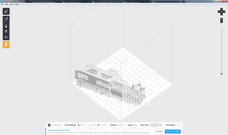
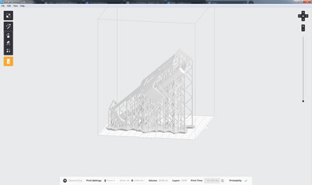
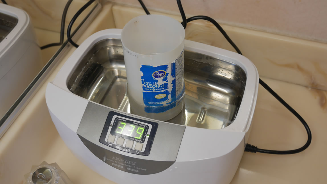
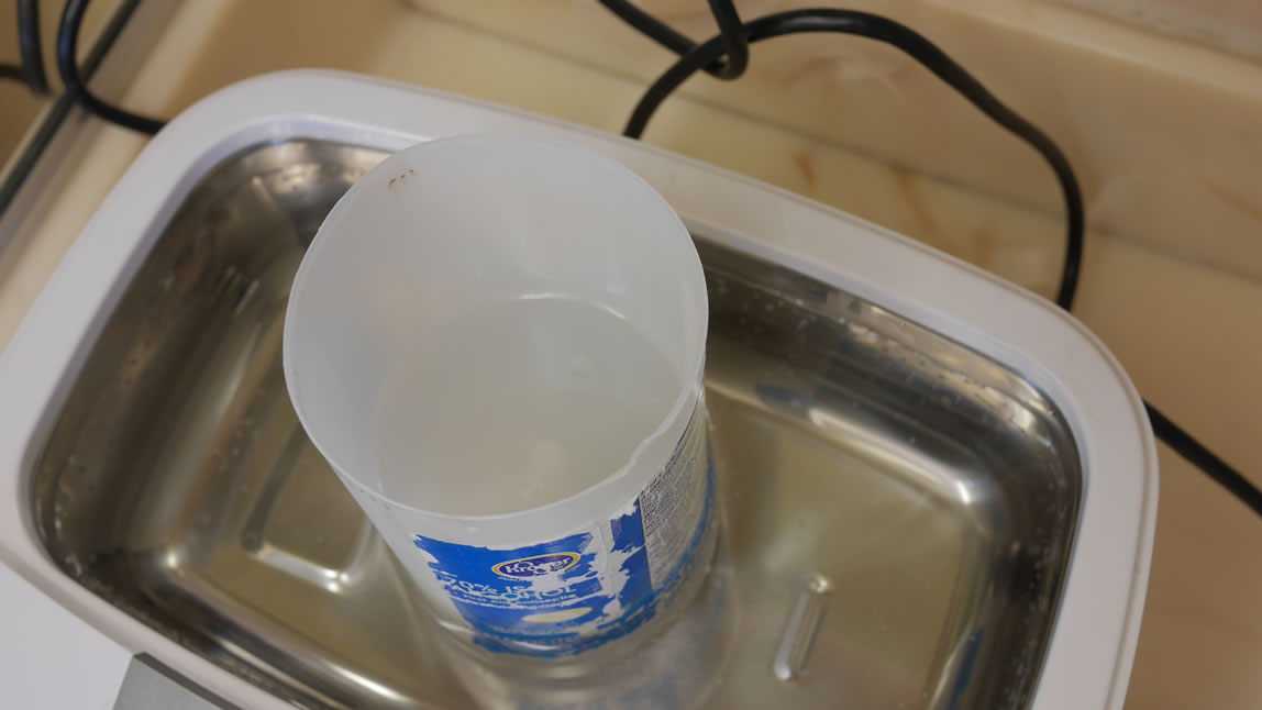
The thing takes about 10 hours to print. The original estimation put it at about 6 hours. After the print, the resin needs to be cleaned up, so the first step is an isopropyl alcohol bath. The part is supposed to soak for about 20 minutes, so I move a step up by putting the soaking tub into the ultrasonic cleaner and running in for about 15 minutes. All the excess uncured resin is dissolved in the alcohol. The print is then dried off and thrown under some UV lights to cure. The Form 2 package came with a nice UV lamp that fits into the dehydrator, so combining the two, I have a heated curing station. The dehydrator is set to 95 degrees for a half hour and the part is placed into the UV lamp assembly and in half an hour, the part if completely dry and completely cured.

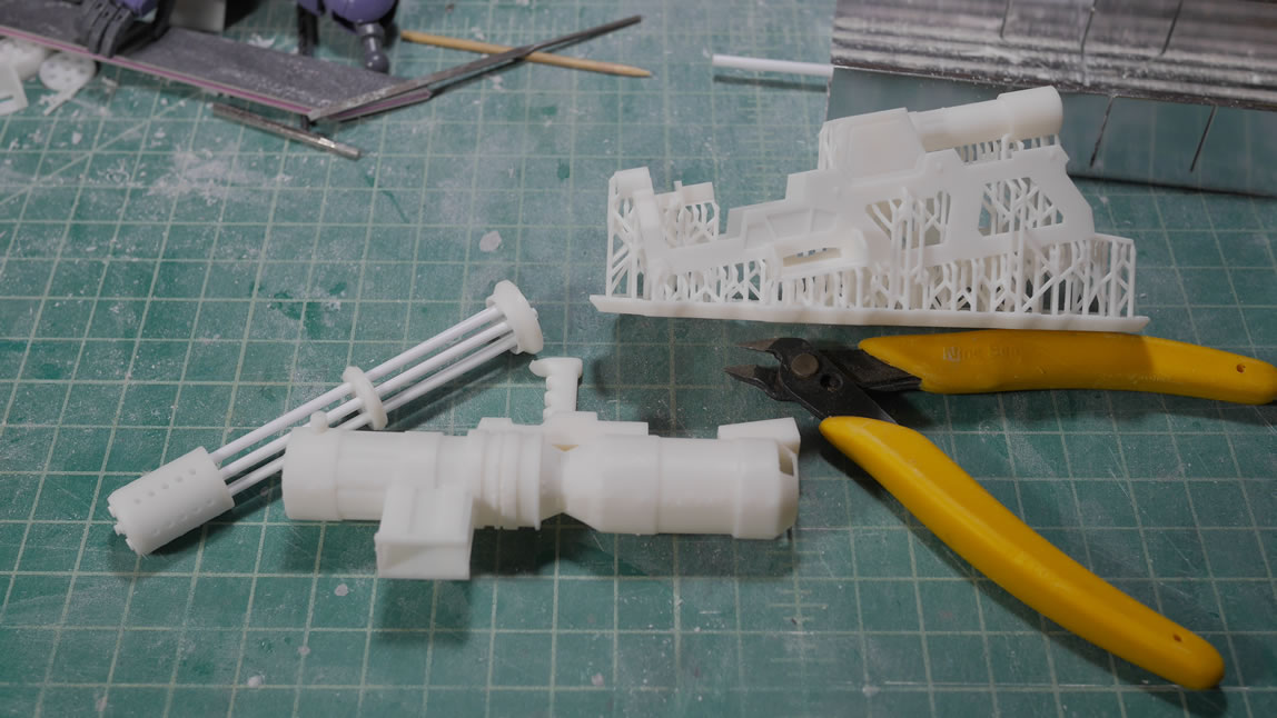
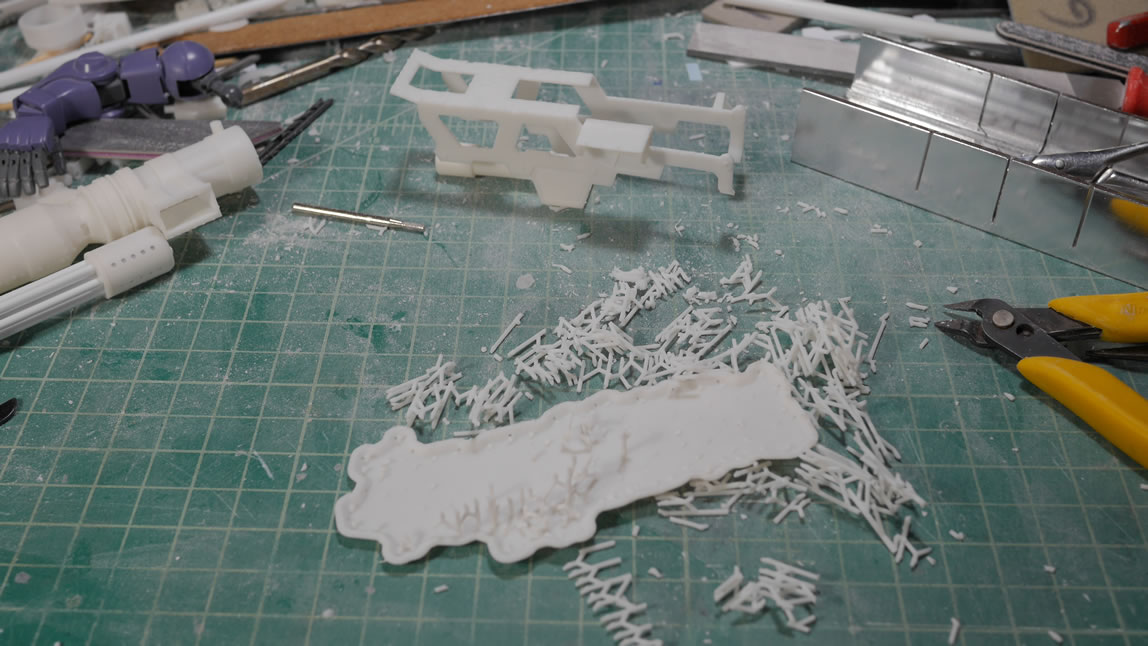
The supports are carefully removed; read clippers to cut the pieces off. If there are supports in delicate areas of your print, it is best to clip the supports off and sand the nubs than trying to break them off with your fingers(because the supports break off fairly easily with light pressure from your fingers). Guess how I learned that lesson? When I designed the main gun, I also hollowed out the tube. This saves on print time as well as resin costs. A liter of the resin costs about $150. So it is a damn good idea to design your objects with that in mind.
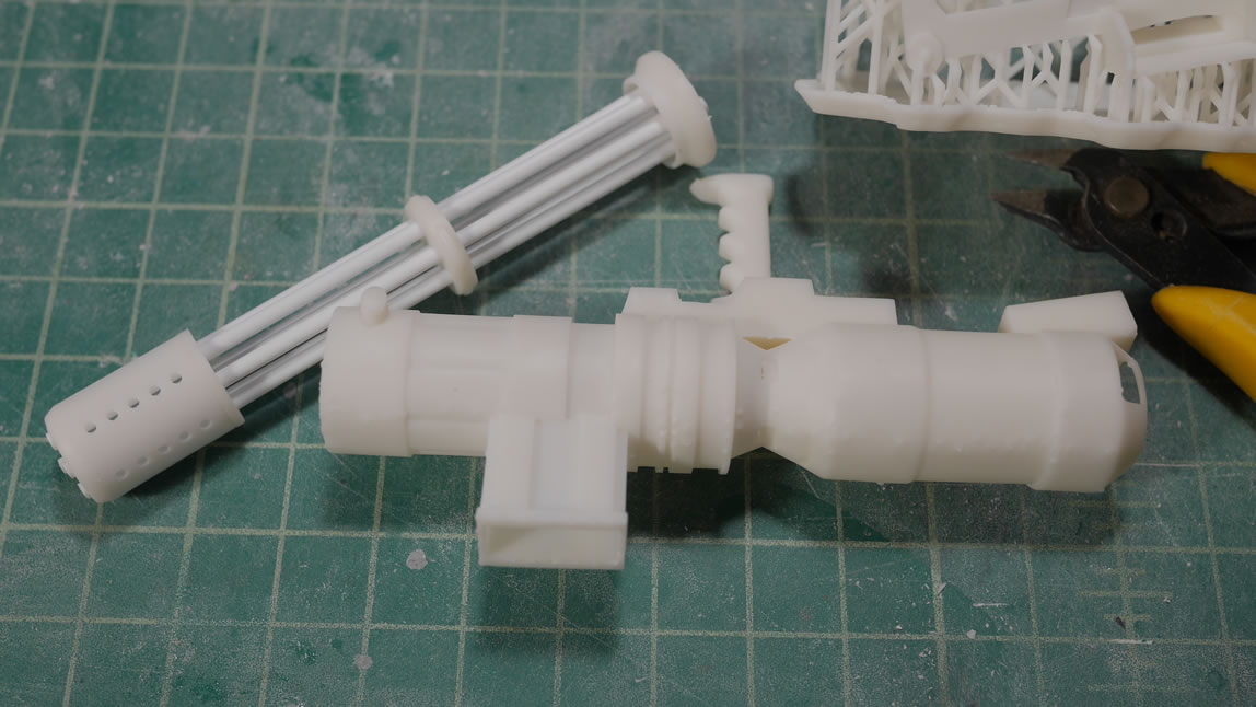
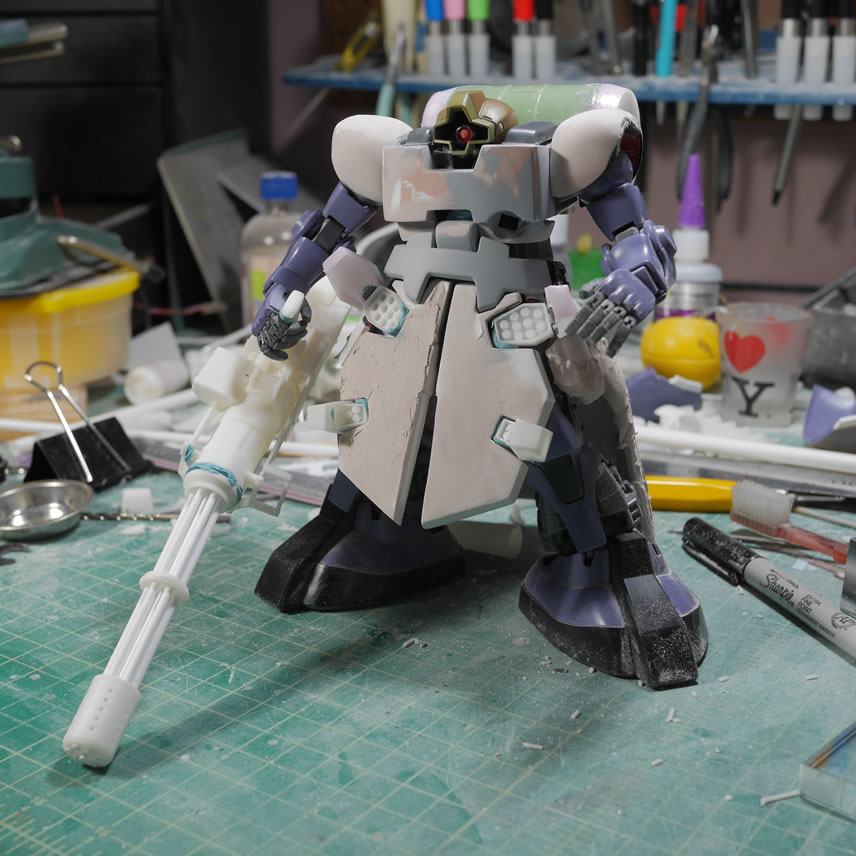
And now the moment of truth, test fitting to check the scaling with kit. I had built the front barrels a total of three different times using different lengths. The first print of the main gun was too long, so I shortened it and I think the scaling looks correct. It is a massive gun, but shouldn’t be so massive that its completely out of scale. The really nice thing about a 3D design is that you can always change up the scaling to get a better fit. This will come into play later; but when testing the fit and size of the design, it is great to have an FDM printer to do all this throw away work a fast print using cheap ABS/PLA materials before getting the scale correct and printing on the very slow SLA with expensive resin.
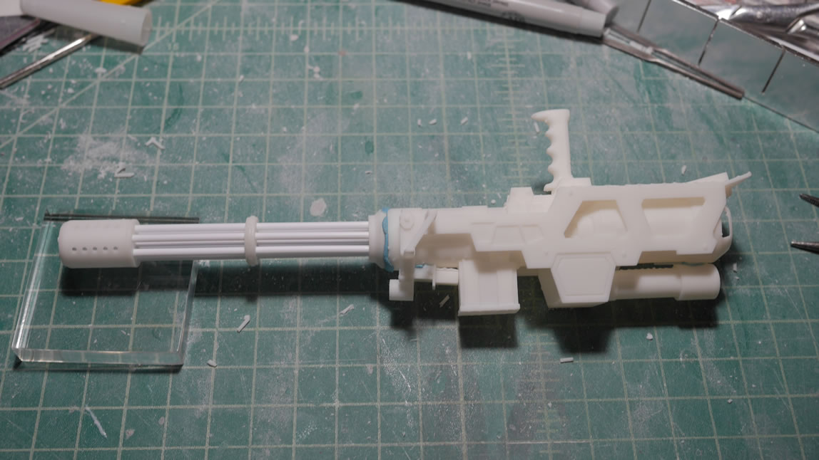
I grabbed several angles to make sure the scaling looks correct. The gatling gun is officially my first almost fully designed 3D part. With the FDM, I’ve always designed augment pieces. So I’m pretty proud of the fumbling around in Blender that resulted in this piece. I definitely learned a great deal while designing and printing.
Feeling pretty confident in my Blender skills. I moved over to Zbrush as I took a class on the software last year. I had forgotten a HUGE amount of the damn class; but I took notes and looking over them, quickly reminded me on what I needed to do. Since I was fairly successful with the gun, I wanted to try my hand at doing the shoulders. Earlier, I had touched on the problem of the shoulders with symmetry, or rather, the lack of and the attempt to achieve it. Since the shoulders are a round shape, I figured zbrush was good for sculpting. The software has a feature that makes the UI transparent and then you can have a desktop image of your reference and turns the software effectively into a light table. Using zbrush’s timeline feature, you can lock the position of the design at different view angles and easily slide between them while you sculpt. It is a pretty cool feature. But I quickly learn that I’m not familiar enough with zbrush so that idea gets abandoned after about a day’s worth of trial and many many errors.

Back to Blender. Blender does have a similar feature where you can import your reference pictures and get the same light table effect. But I haven’t figured out how to get it as smooth as zbrush in switching between views and locking down those views while i work on the design.
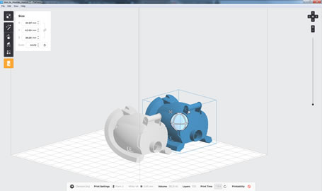
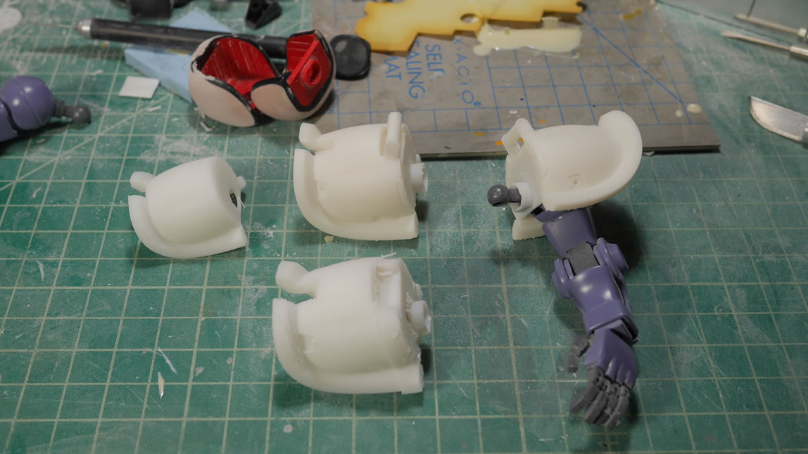
Another week or so is spent to design the shoulders. The nice thing here is that I only need to design ONE shoulder. I started with the inner shoulder piece and after measuring distances, just designed that with straight cubes and cylinders. At this point, I hadn’t figured out how to do the rounded shapes or even the rim for the shoulder. A few youtube videos later, I discovered the Nurbs Surface. Working with this, and the mirror modifier, I was able to get a pretty close representation of the Dom’s main pauldrons for the sides of the shoulder piece. Some more youtubing and I learned about using bezier curves to create the shoulder rims details. Once the top was done with another nurbs surface, the rest of the details were fairly easy. The shoulder bar as well as the free floating detail piece at the outer end of the shoulders were simple shapes and cuts. The scribbled line as well as inset details were done too using simple shapes and booleans. The whole project took several hours every day for about a week before I was ready to actually print the thing. I have a rendered colorized view, another blender feature I learned to get another visualization for the designed object prior to printing.
I designed shoulder to have separate elements such as the end details pieces as well as the inset details. This way, I can do a quick print on the FDM to check for sizes using the base shoulder piece. In hindsight, I could have just tested this against the internal shoulder piece I modeled first and that would have saved even more ABS and print time. The first print was too small, so I made the adjustments and printed again. My FDM printer shifted a little during the print (as they sometimes do if the table shakes or something odd happens). But the printed part is a good fit so I know the dimensions I need for the SLA print.
Design one shoulder, print two. With the scaling done, the part is sent to the Form 2 to print for the next 6 hours.
6 hours later, the print is done and I do a test fit with the arm and everything looks good; almost. I do notice that the end detail did not print correctly and the ends of the shoulder rims are not completely printed. This is a design mistake and not a printer error. That detail piece was designed as a free floating piece that is connected at the end of the shoulders – since the reference pictures showed this as a free floating part. To fix this, I needed to add a mesh from the main shoulder piece to this detail part. Lesson learned here is to make modifications and judgment calls when following exactly with the reference or deviating when necessary.
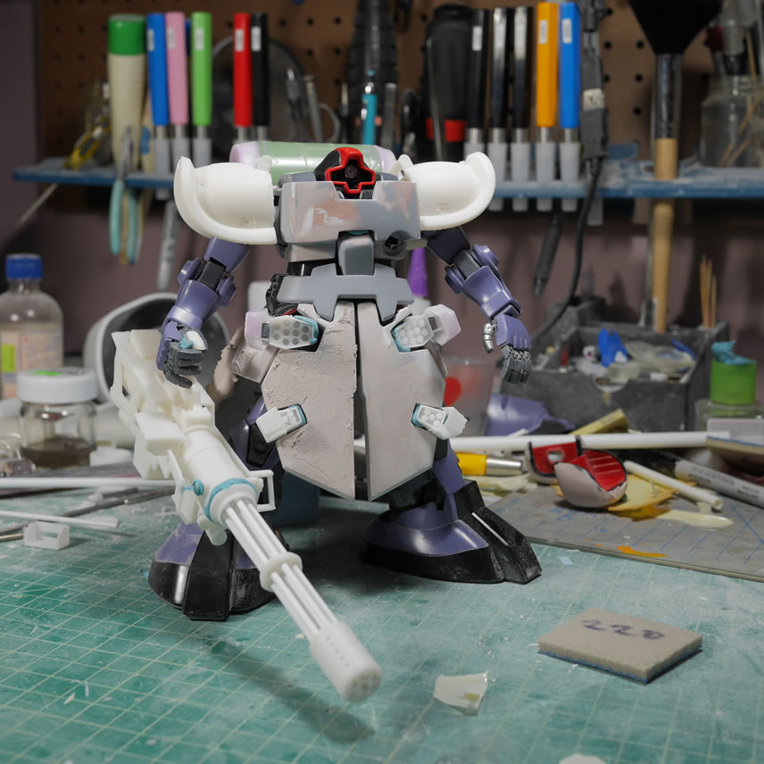
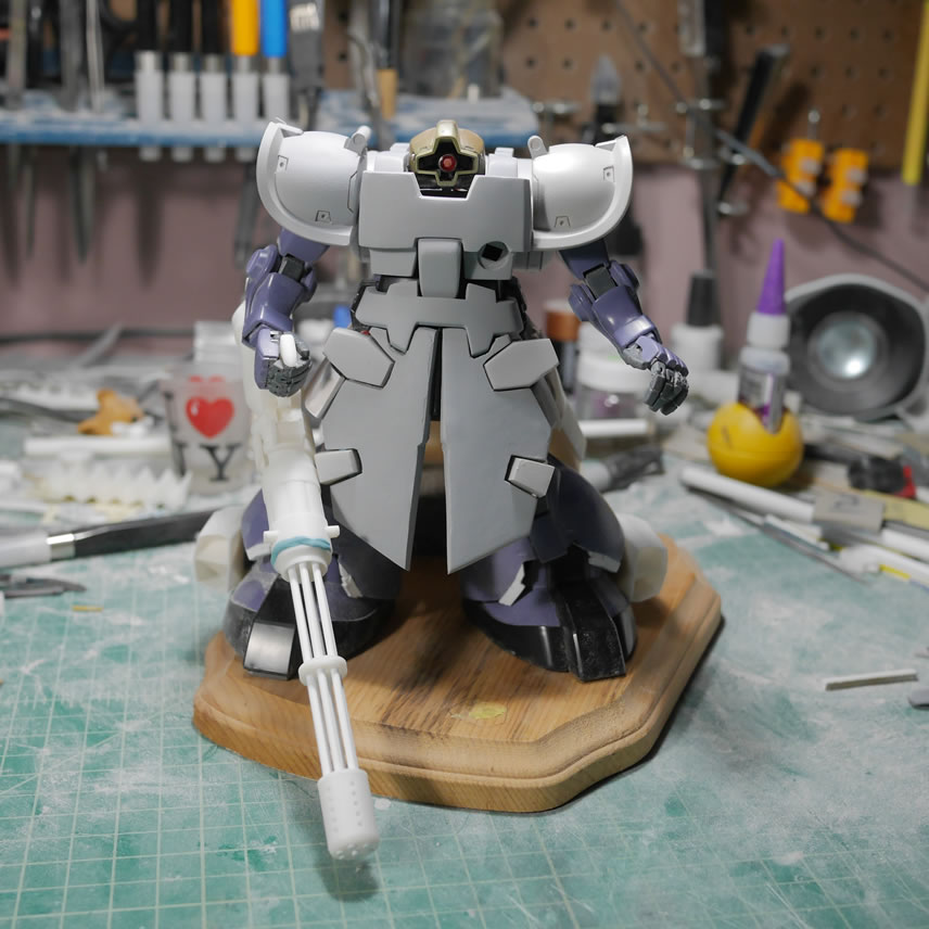
Here is a mock up with the Dom with the first shoulder print. I’m getting a Kondo style feel here, but this feeling doesn’t hit me until a bit later.
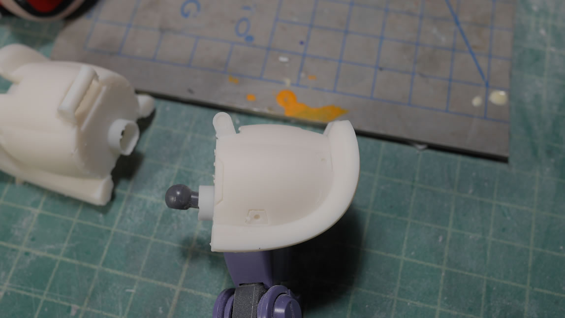
Another 6 hours later and I have the correctly printed shoulders. You will see that the end of the shoulders are not missing now. This is a good lesson in print orientation and limitations on what can be printed depending on the orientation. I let this sit for a day and then looked at it again and made a comparison to the reference pictures. The shoulders were a little too long. Scaling with the rest of the kit, they didn’t look correct to me. Again, that Kondo style feel is hitting me ever so slightly. From the side view, there is just too much room from the internal shoulder piece. The internal area was a little too tight so that the shoulder ball doesn’t have room to move and is actually being held in place by the resin shoulder internals. The cylinder connection point for the joint piece that juts out from the should ball is also too large and is not the actual area holding the arm to the shoulders. These are all things that I completely missed in the initial test print. I was a little overly excited to get the print sent to the SLA. Another lesson learned here. Patience is key, and would have saved me at the minimum of 12 hours of extra print times and resin.
I went back to the 3D design and shortened the shoulder length by 4mm; this is small but in the scale of 1/100, this is about 1.3 feet of difference Small, but noticeable. The detail bits were adjusted to fit the new size. The original connecting cylinder piece was a little too thin so I thickened that up. It was still too large after printing, so I designed an insert that works to attach the original part’s frame piece. I widened the internal shoulder piece to give a little more room for the shoulder ball. This made the addition of the round insert piece more important as the earlier print had the internal shoulder walls holding the arm in place where now the joint area is the contact point for the shoulder and the rest of the arm. How it should be.
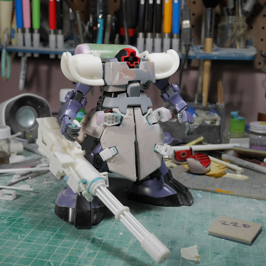
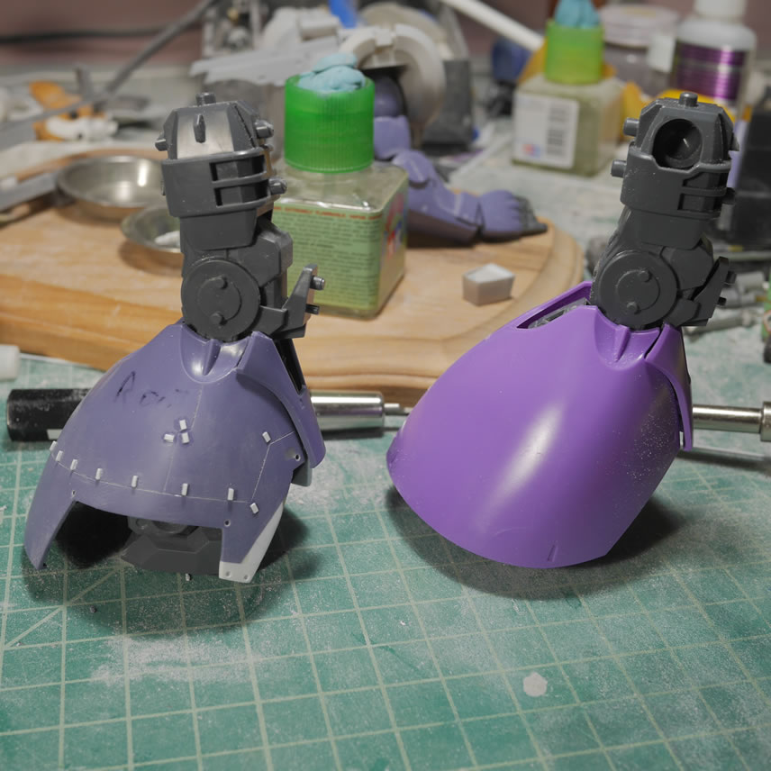
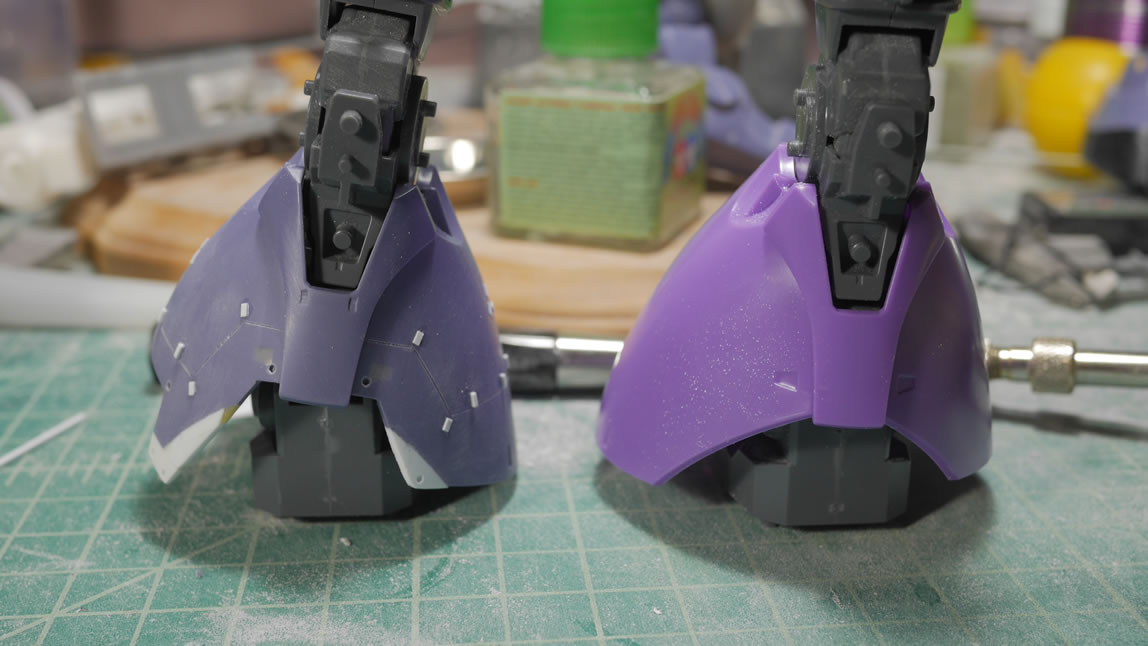
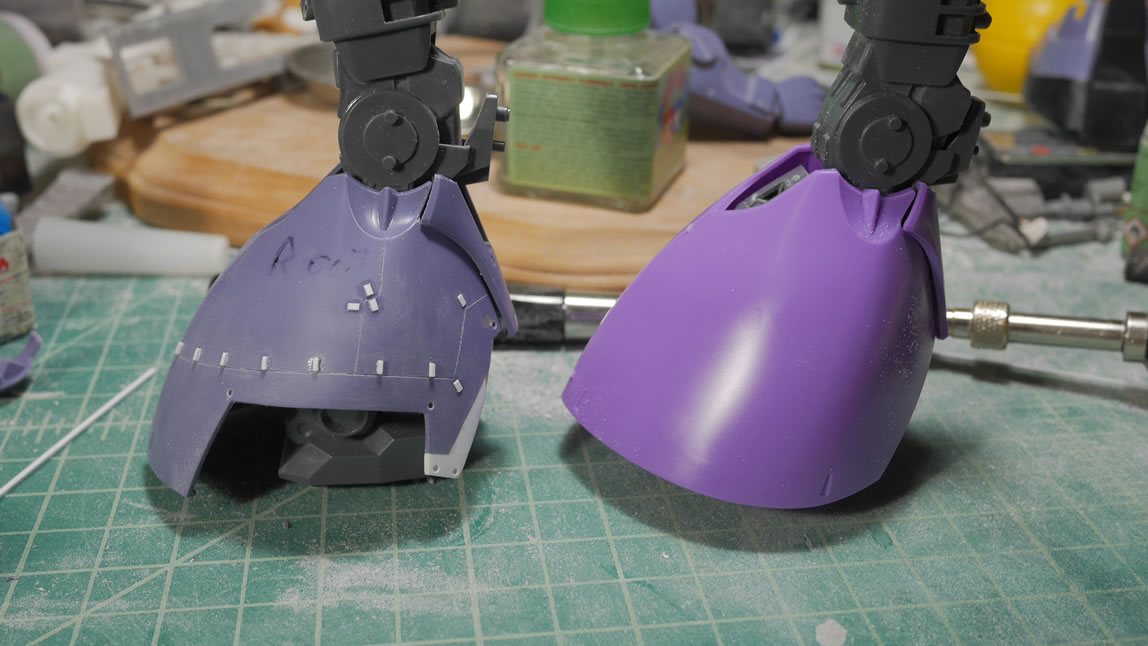
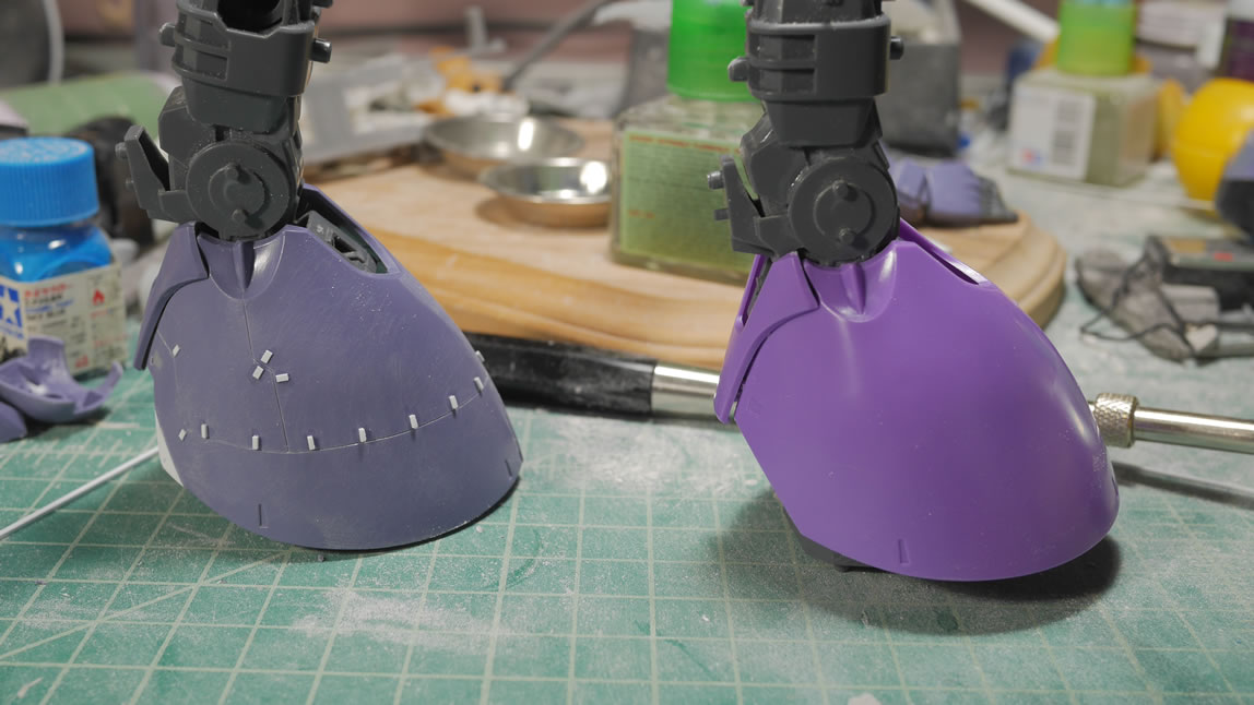
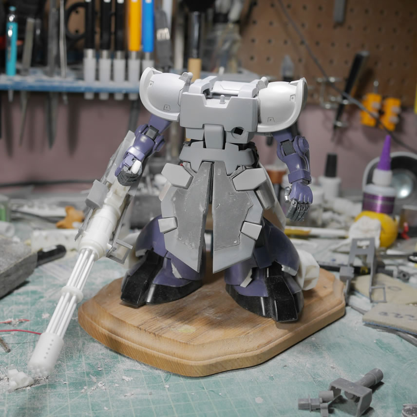
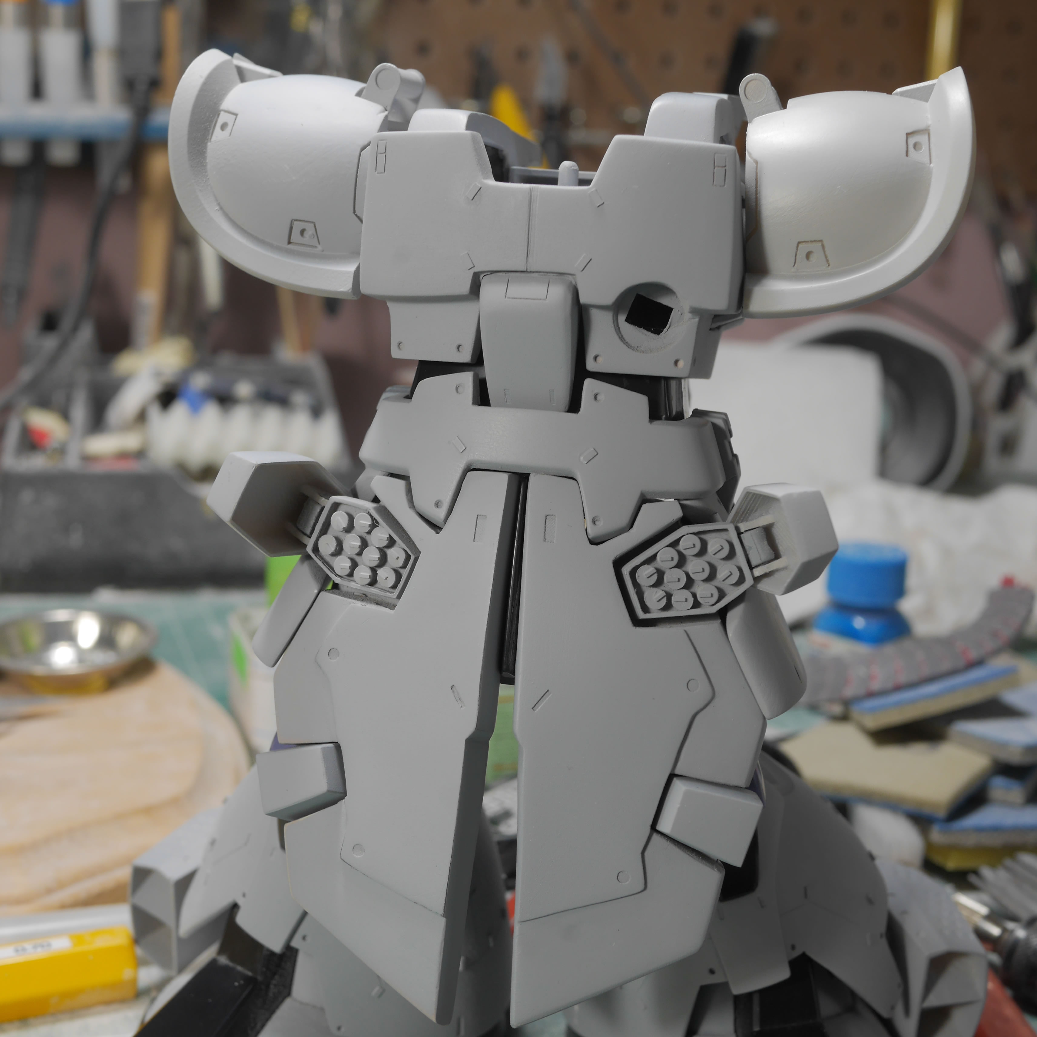
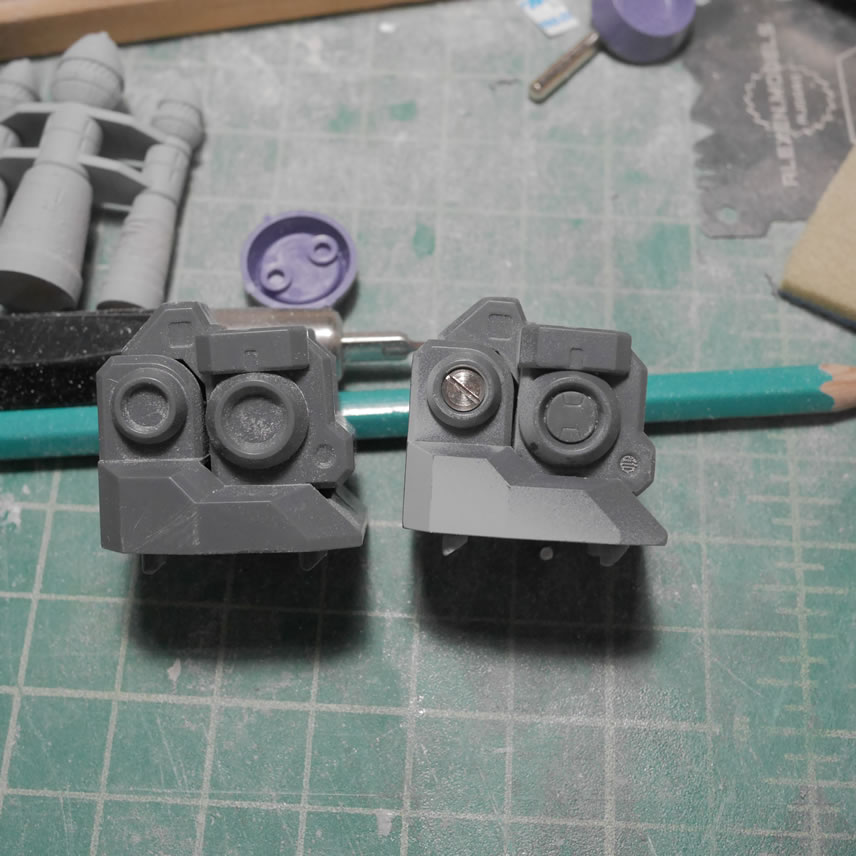
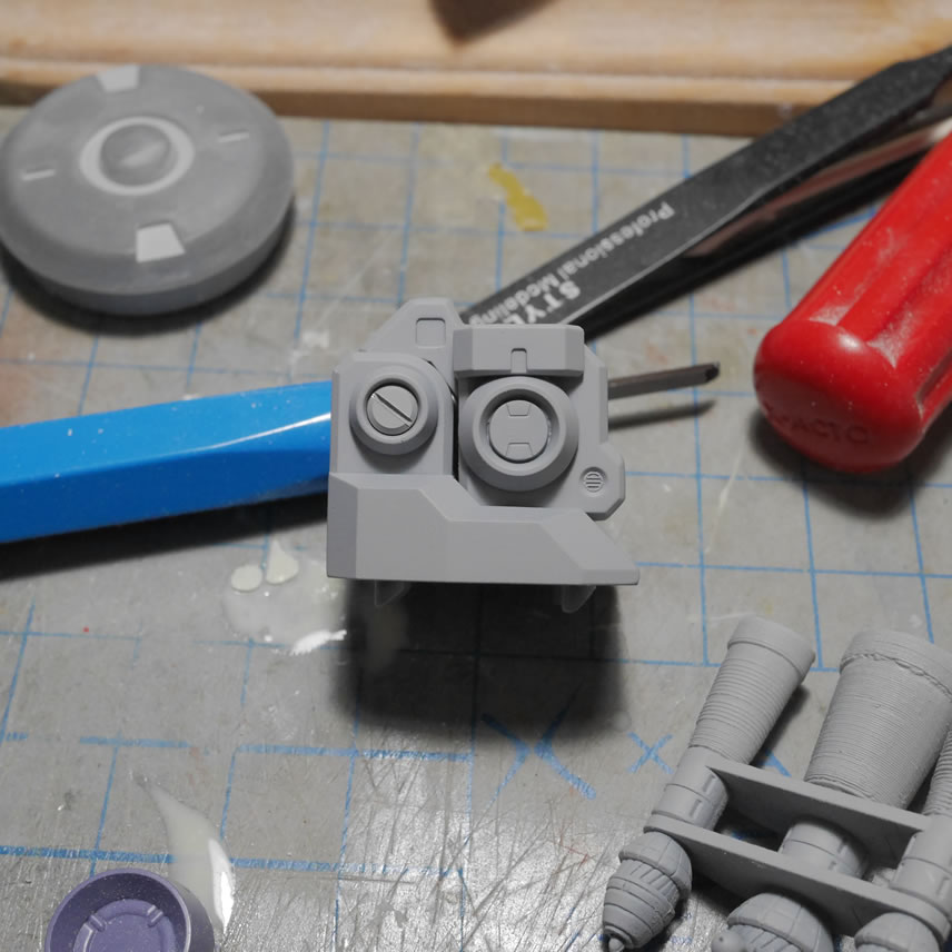
Another 6 hours later and I have the below comparison picture. The left side is the first prints with the larger shoulders and the right is the shortened shoulders. Looking at the whole kit, I think the shortened shoulders scale better.
Below are the rest of the angles for the shortened shoulders. Overall, i think this looks much better. Work continues, but I’m starting to get more comfortable with Blender and naturally, this means more 3D designed objects; to help “augment” the scratch building…
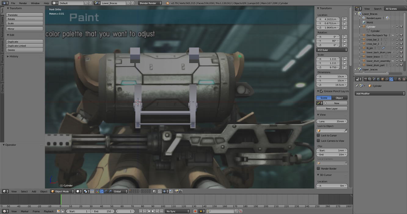
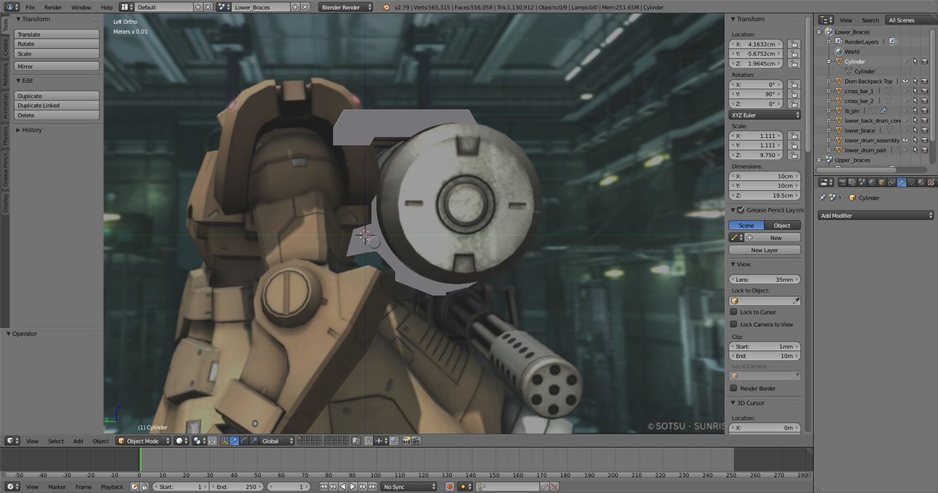
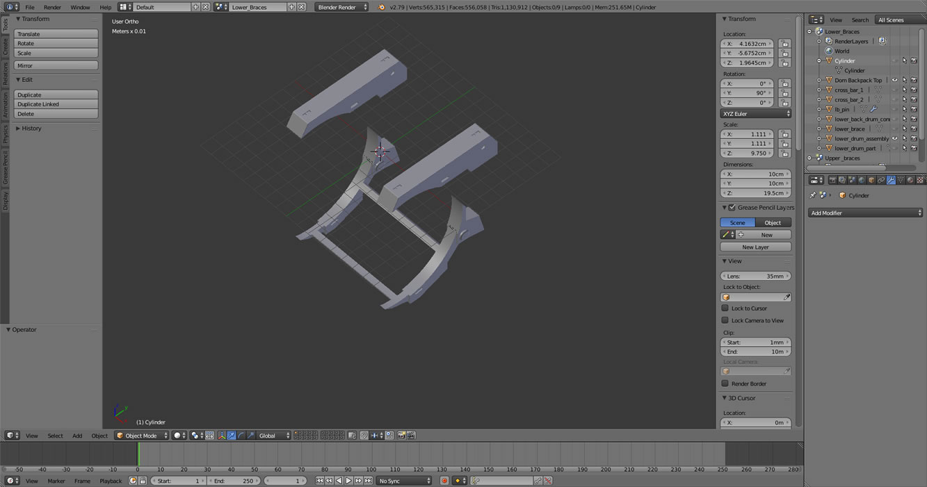
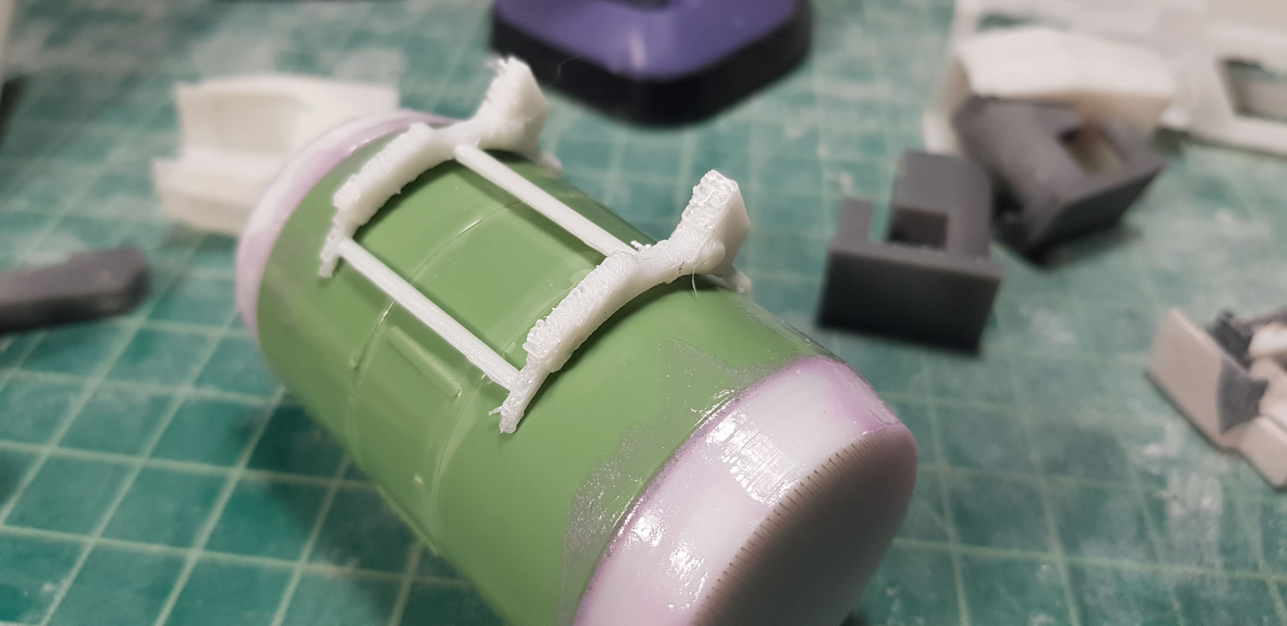
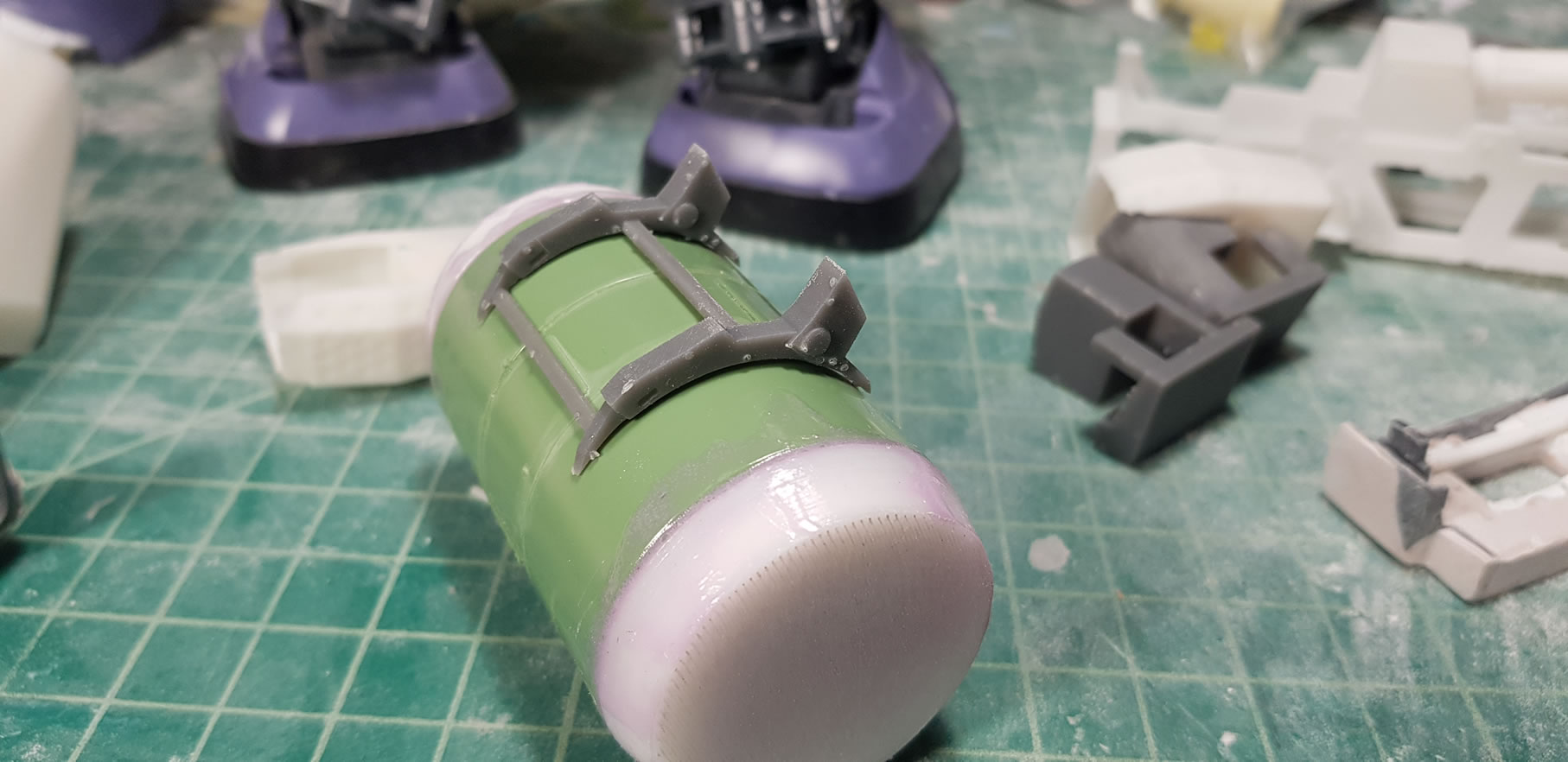
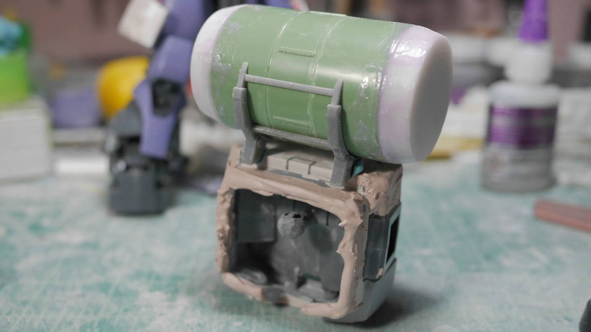
April 11, 2019: As I get more and more comfortable and knowledgeable in using blender to design objects in 3D, the more addicting this becomes. Using the image reference feature in blender, I’m able to quickly design out parts for the project. When I first started working on the project, I didn’t pay much attention to how the ammo drum attaches to the back of the Dom. So I created a connection part that inserts into the back. I will probably keep this as I continue to build; but as I did more research and looked at the Dom more, I found upper and lower brackets that hold the drum to the back of the suit. Using the reference pictures, I designed the upper and lower brackets.
Also in this post, we recently printed some new shirts for this year’s SCGMC. Our new SCGMC mascot has its own t-shirt design. And since our theme this year is the “Ball”, we got a design printed on both a grey and an orange shirt for the two versions of the Ball from the various animes. The last shirt in the group is the judging shirt from SCGMC 2018 that we gave to our judging volunteers. Click on the images to get to the store, this is how we fund most of what we do for SCGMC.


Going back to the feet details I printed from the last update; I needed connectors to these detail designs to the foot. Once they were designed, I printed in grey resin, for which I discovered has an even finer print setting of 25 microns verses the white resin’s 50 microns as the finest setting. These were connecting joints so I didn’t need 25 micron level of detail, nor did I need 50 microns. So I went with the 100 microns for the quickest print. I printed the connectors without thinking; and once they were printed, I went to test fit the detail bits and realized my error. Since there is a left and right foot, I needed to print a left and a right connector joints. I had only printed one side. Back to the printer, I made a mirrored version of the connector piece and a few hours later, I had the correct connector pieces.
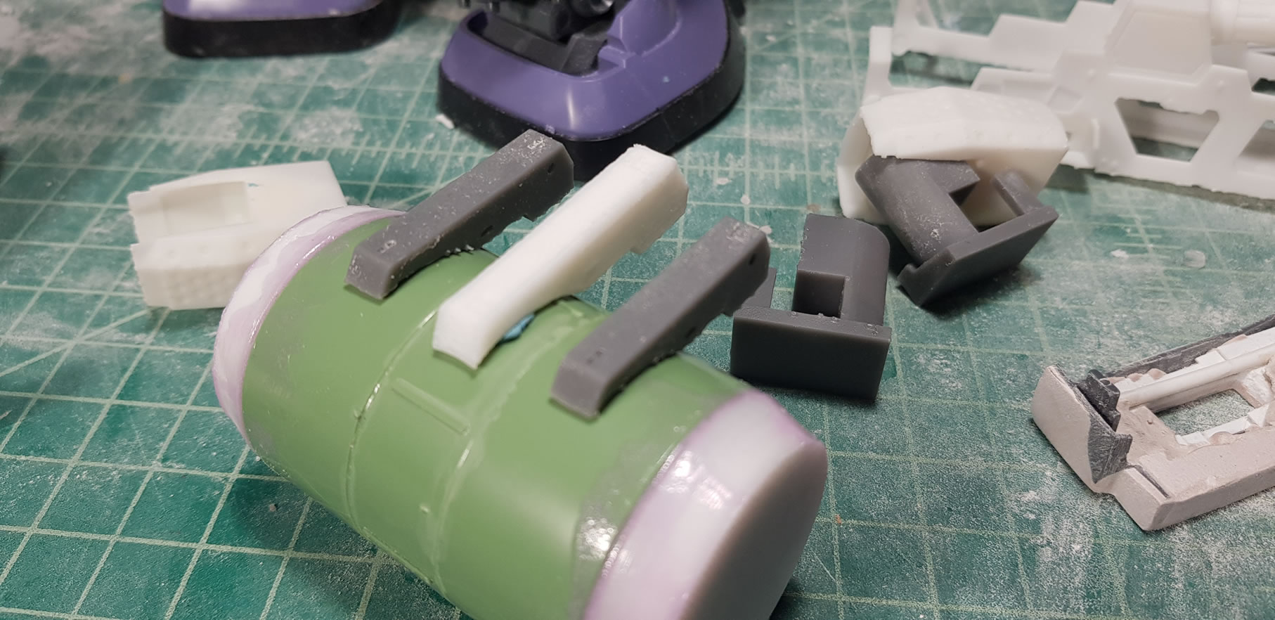
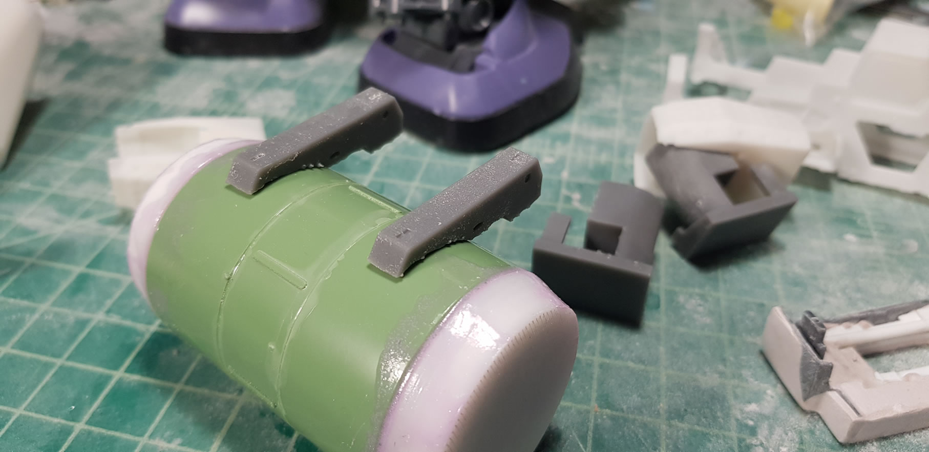
Going back to the ammo drum brackets, I printed the parts first with the FDM (white pieces) to help size the parts before printing in the SLA. I dropped the size of the upper brackets by 1 mm and raised the size of the lower bracket by 1 mm and sent this off to the form 2.
Below is the test fit against the ammo drum to be and the adjustments worked out quite well for both the upper and lower brackets.
3D design and printing parts is VERY addictive. There was a pretty big learning curve for me with blender and that took a bit of time with trial and errors upon errors. I am almost tempted to go back to the gun frame and completely redesign it from scratch with everything I learned since working on it. But now it seems like the most efficient use of time to design and print the parts and then combine them to the kit. Which is now the next step I need to work on, getting everything fit together. Actually, the next step is the clean up work on the 3D printed parts, then it’ll come to combining things.
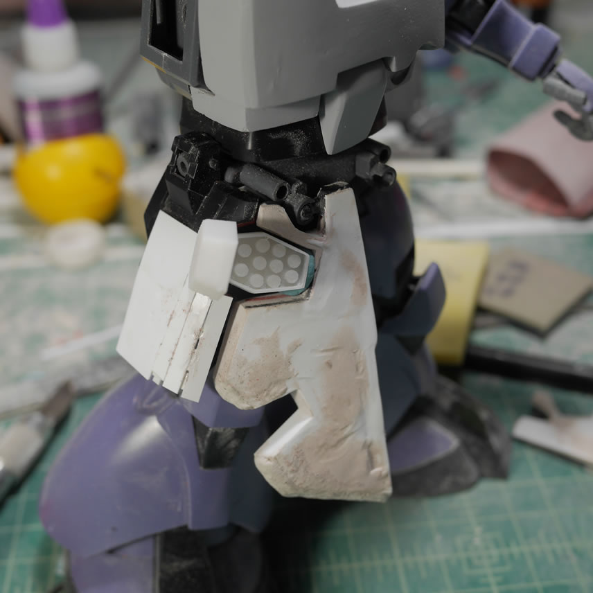
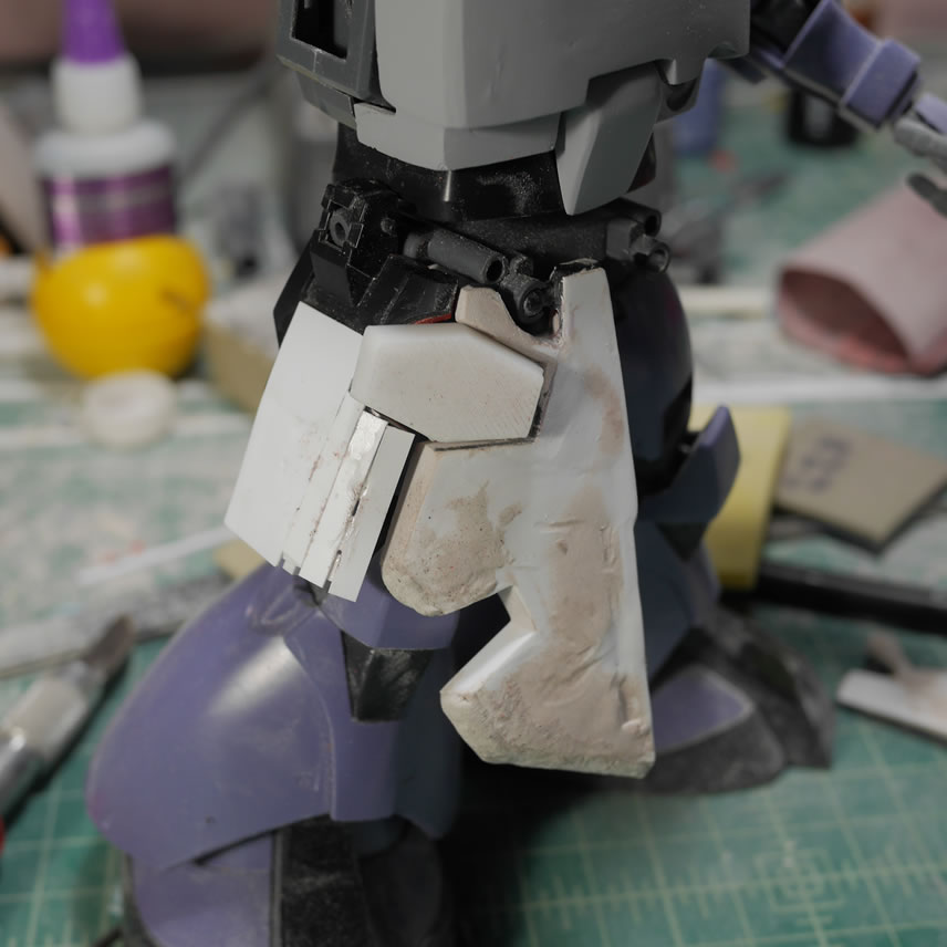
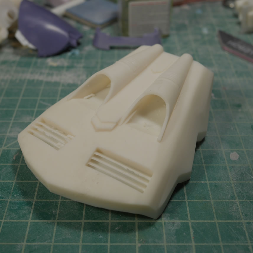
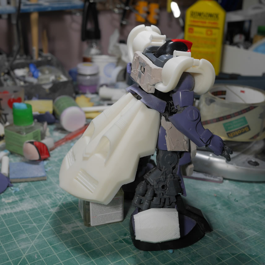
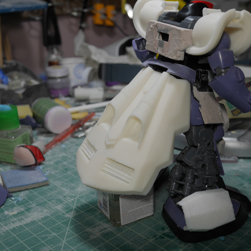
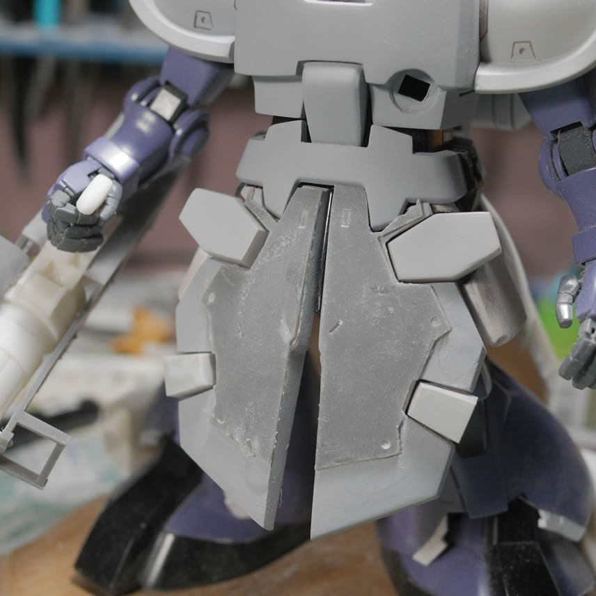
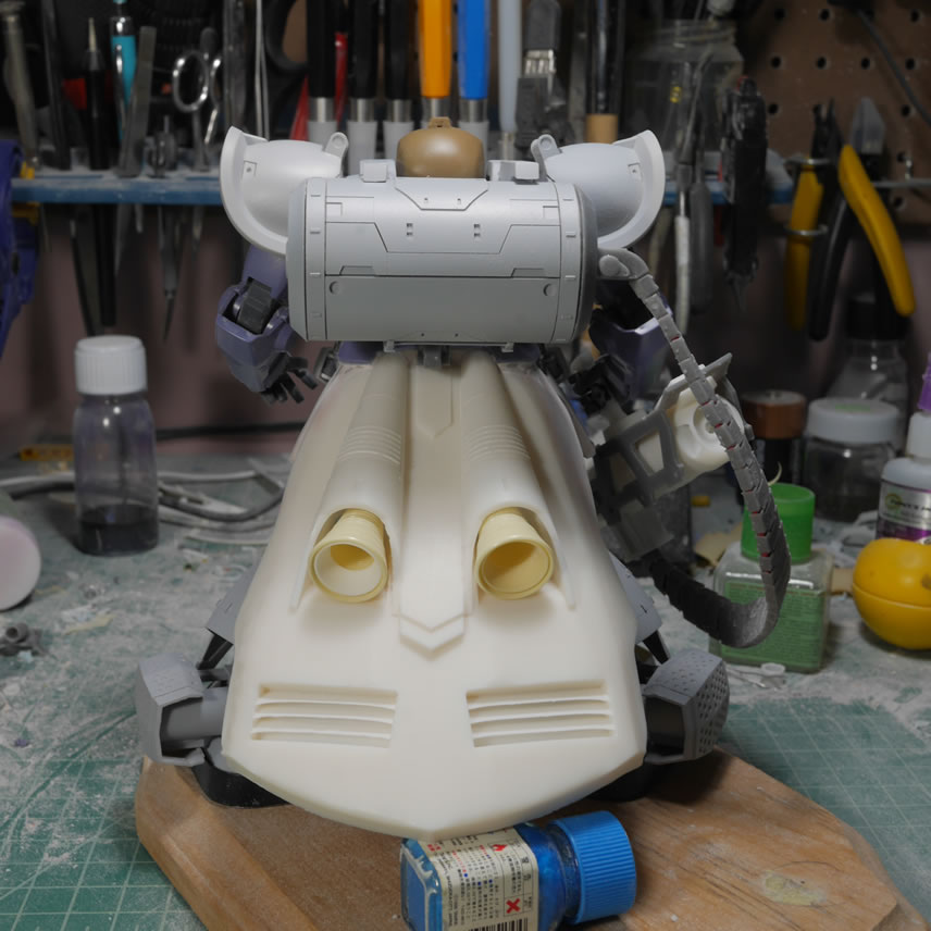
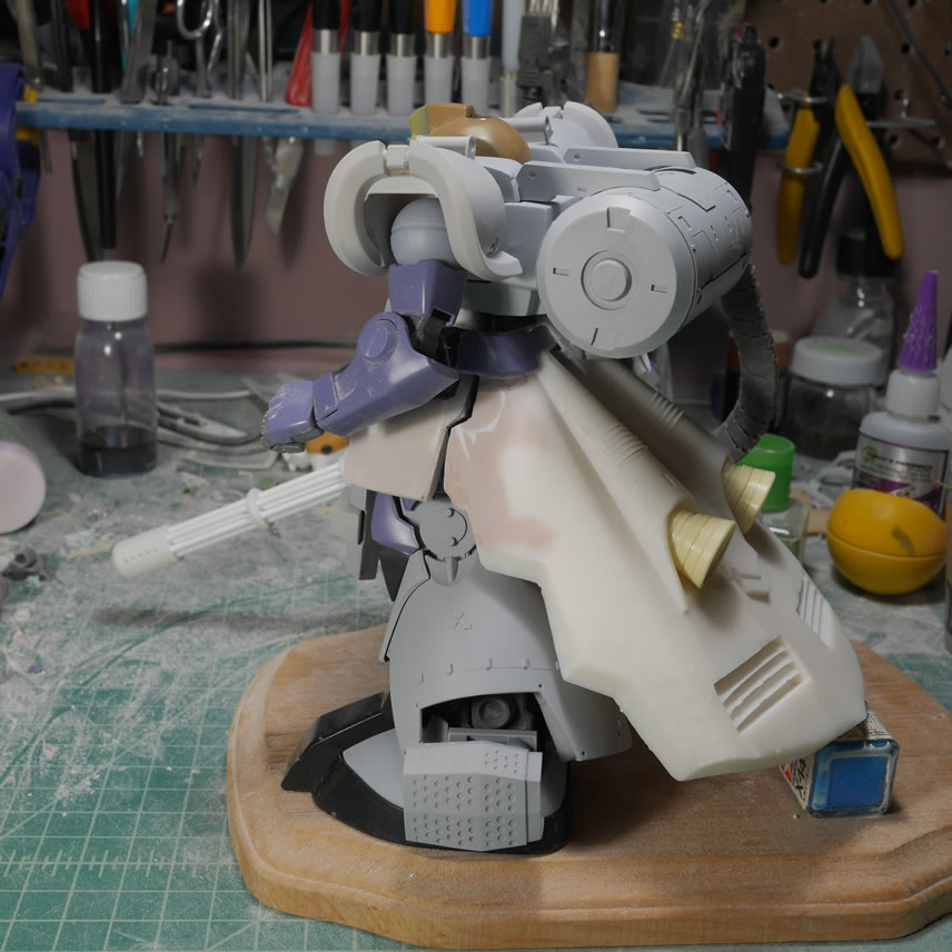
May 29, 2019: It has been a while since I made an update. Real life got a little busy with a trip to Toronto for a wedding and just being busy. I’ve been getting work here and there with bits and pieces. One of the major bits is the skirt. I had used the original skirt and tons of bondo and plastic to build up the rear skirt. My skills with Blender has gotten better and some slow down at work tempted me to try designing the skirt. Printed out, it’s not perfect and it’s slightly heavier than the bondo version, but it look fairly decent. There is still a decent amount of work needed to meld the piece with the waist which was easier with the bondo piece because it was built up from the original rear skirt. Here is the skirt and a quick mock up with the kit.
This update is fairly large since it has been over a month and a half since my last update.
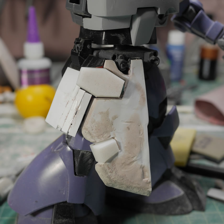
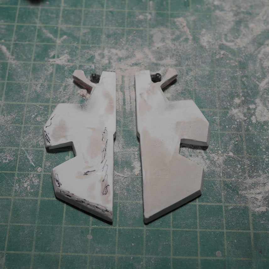
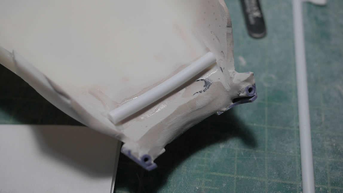
Returning to the printed skirt, I glued in a support beam (plastic tube) and then built up some bondo so that I can fill in some gaps between the original top skirt piece(purple plastic bit) and the printed skirt piece. The bondo also works to add surface for drilling in some holes for new support points to the kit’s waist unit. The waist unit’s contact points are measured against the rear skirt and the new holes are drilled. There are some gaps between the rear skirt and the side skirts, so some base plastic plates are glued to the rear skirt that will eventually be used to support a layer or two of bondo.
The next step, once the above support layer of bondo cured, is to drill the holes and add in some brass/aluminum rods as the new connection points. These also work as support since the damn rear skirt is pretty heavy. Bondo is applied to the sides to build up those sides of the rear skirt where those points meet up with the side skirts.
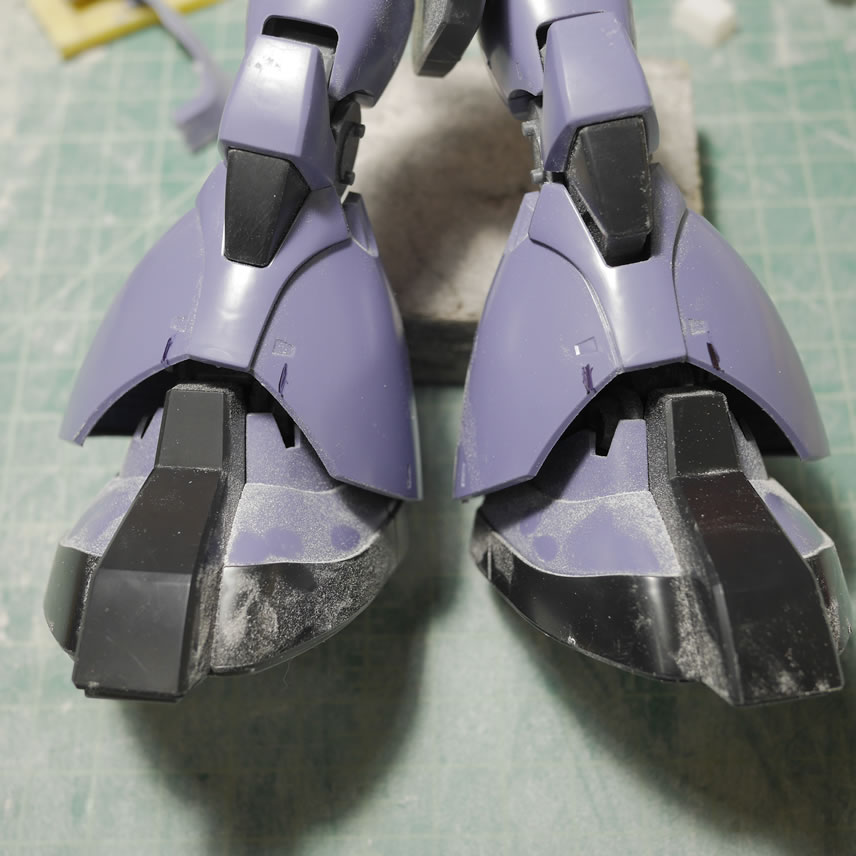
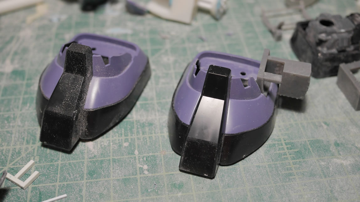
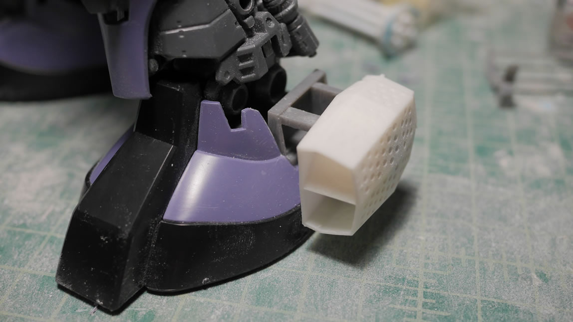
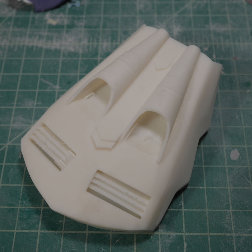
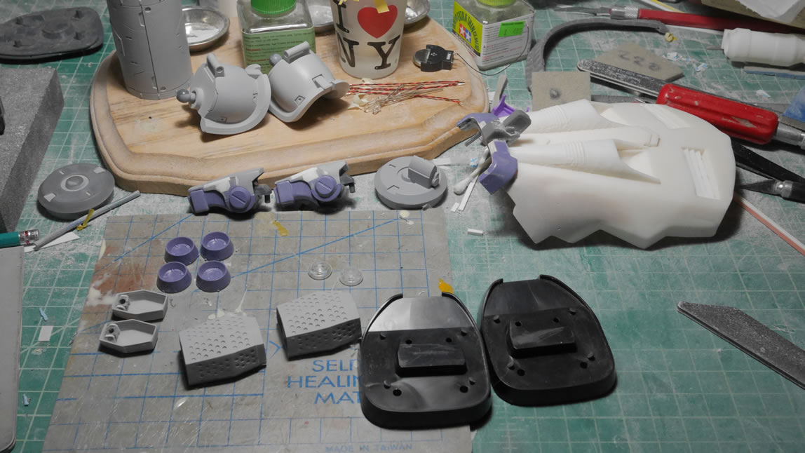
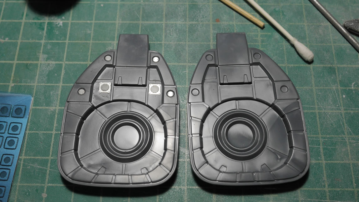
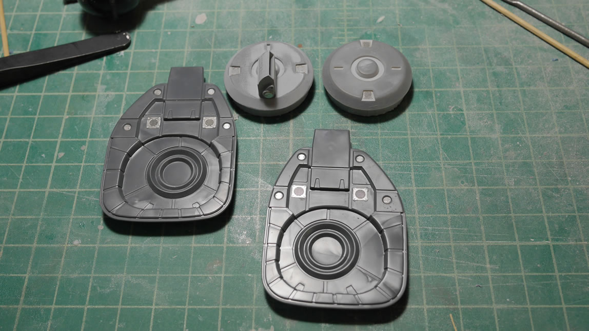
Moving on to the feet. The last post touched on the 3D designed foot vents that is similar to the Dom Trop’s foot vents. Since this kit is probably closer to the Dom Trop than the standard Dom, a decent amount of work is necessary to modify the legs and feet. With the vents pointed, I did a quick size and test fit against the feet to make sure the look correct.
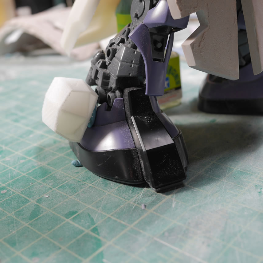
I designed and printed a connector joint that attaches the vents to the feet. My previous progress post talked about printing mirrors of objects so we don’t run into issues of two left feet pieces. With that resolved, I now need to make mods to the feet so that the connectors and the vents fit and look correct.
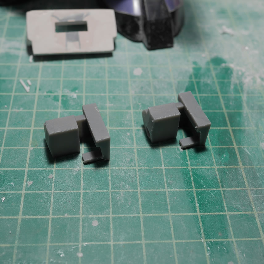
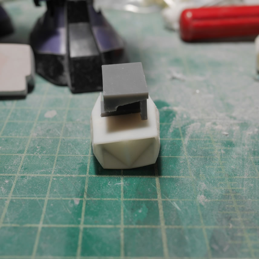
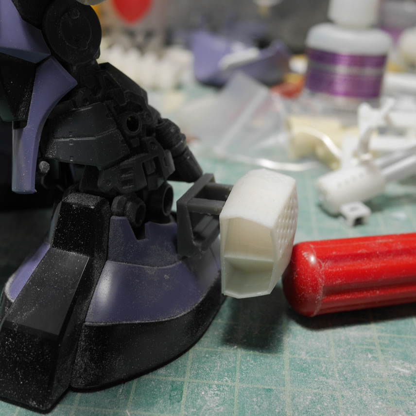
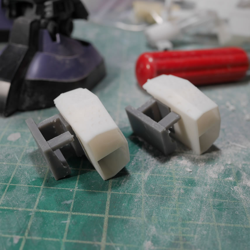
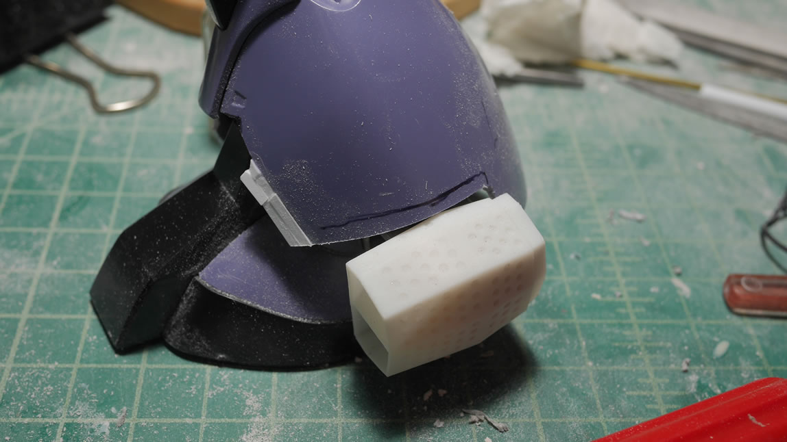
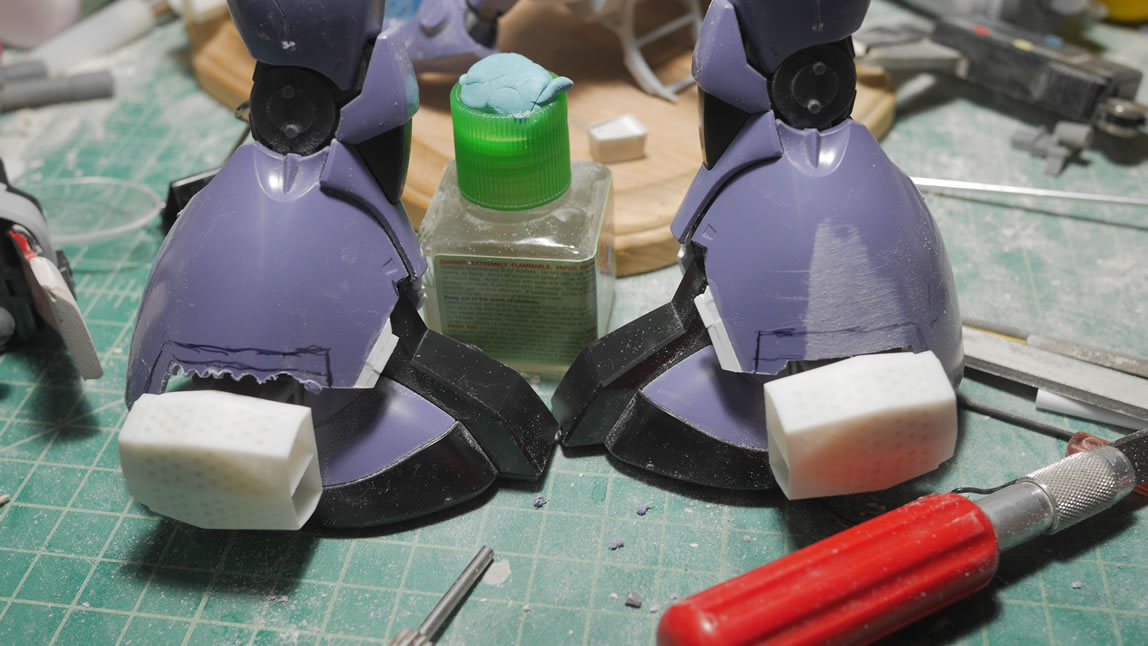
I cut the outside sides of the feet to fit in the connector and vent piece. Cut, sand, test fit, and repeat until the joint fits correctly. Once done, I glued the connector piece into place. The vent parts are just being held to the connector joint with some sticky tack.
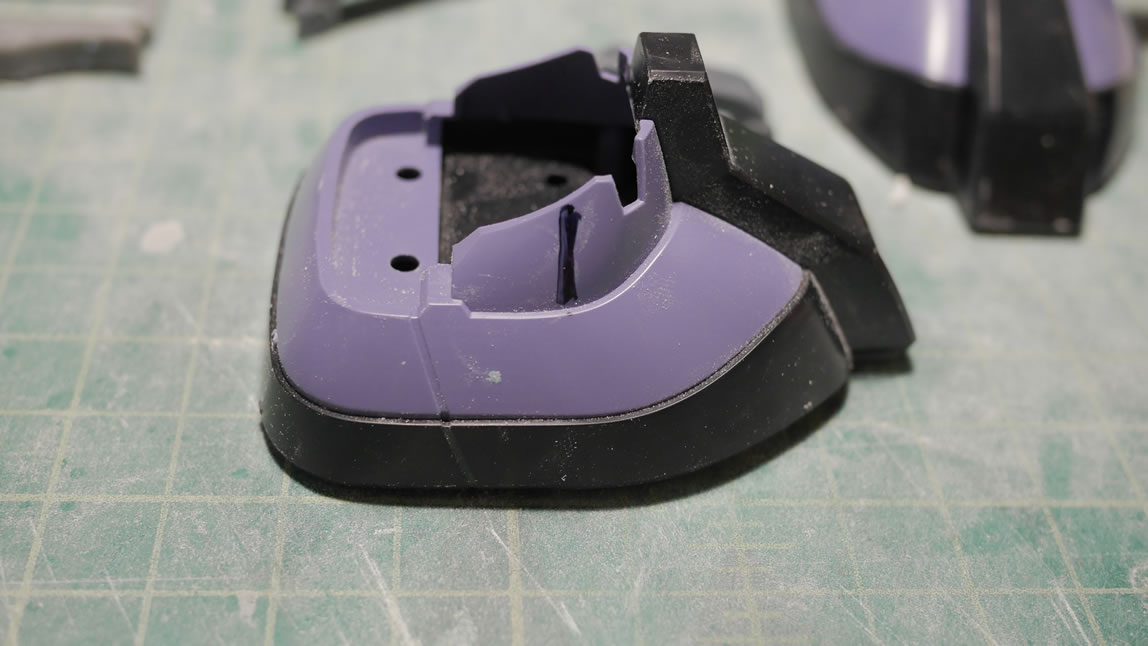
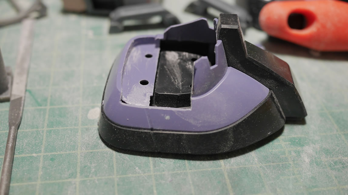
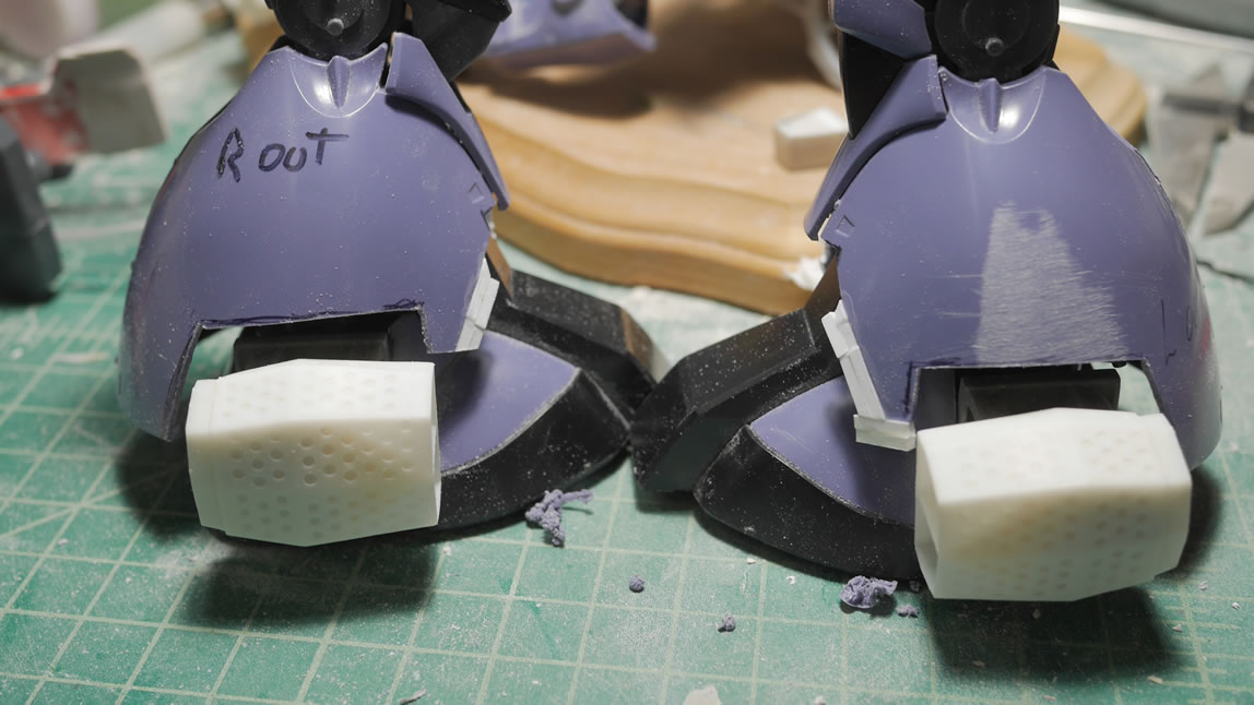
The legs got some cuts and plastic glued several weeks ago. Time to revisit and start working on the legs. I measured and drew some guides for cutting the outer areas of the legs. I have the legs labeled clearly to make sure the correct area and correct legs are being cut. The plastic glued to the front of the legs gets some sand work to shape it. Some plastic is cut away, and some plastic is added, and a sanding stick works to shape everything.
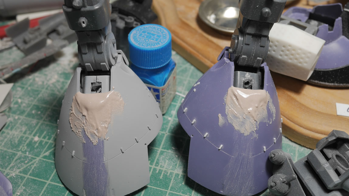
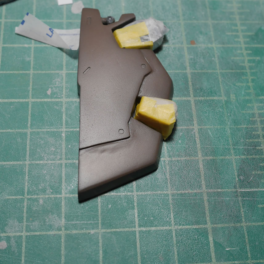
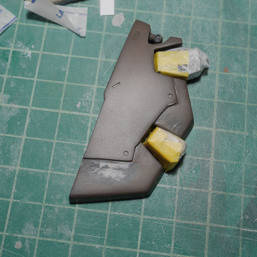
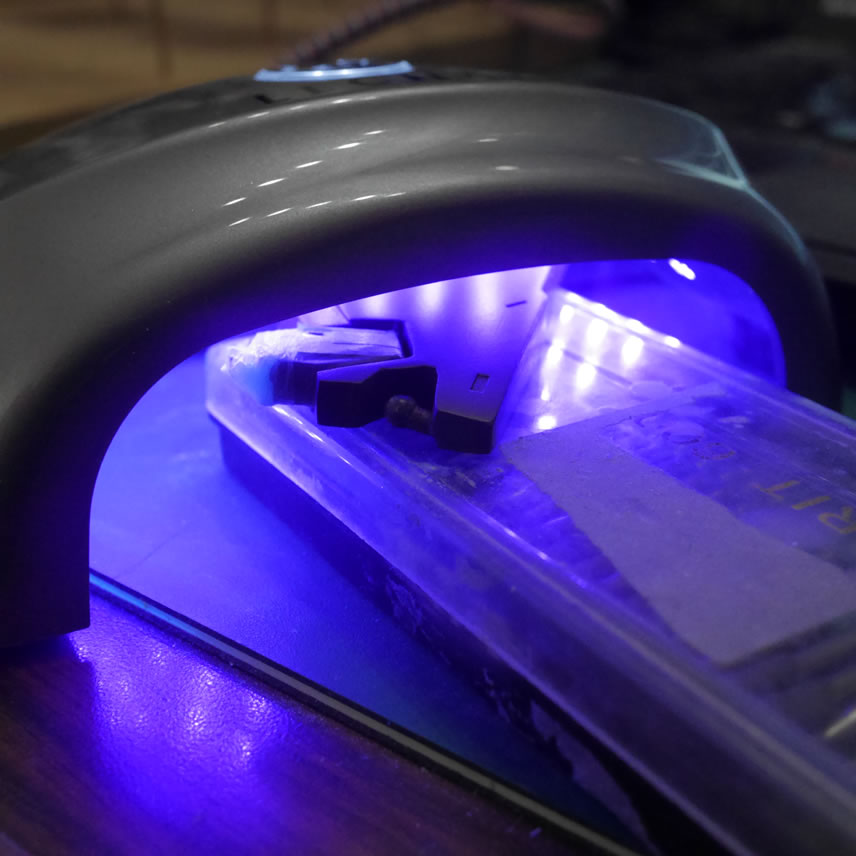
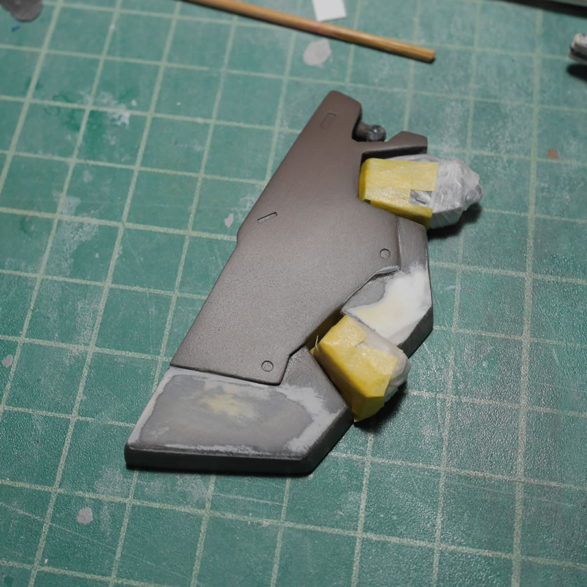
More test fitting with the feet to ensure everything looks correct with the reference pictures I have. Light curing putty (the yellow bits) is used to quickly fill and sand the surface. The last picture is a comparison with the original Dom’s leg to see differences.
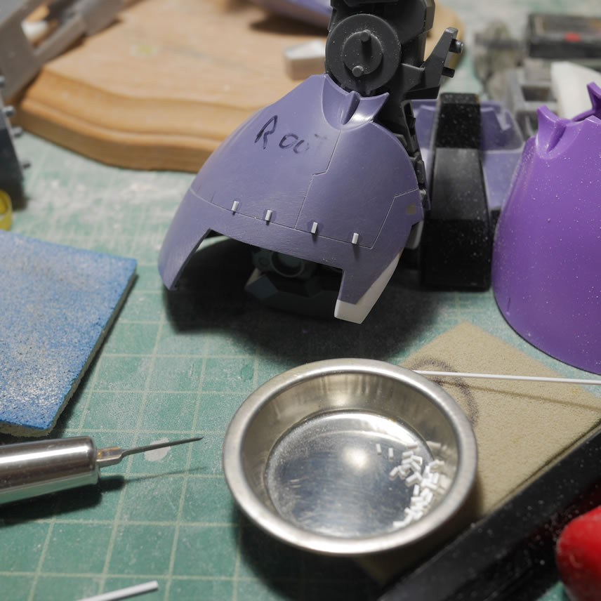
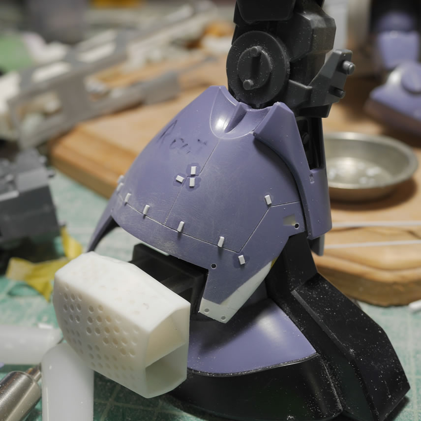
Once the base shapes are cleaned up, time to get into detailing the legs. I scribed in some lines with the BMC chisel and dyno label tape as well as tamiya masking tape as guides. The lines were measured and drawn in pencil first to check for the look. Once the look and measurements were correct, the lines were taped up and the chisel run. I first started with the .2mm chisel. Once I removed the tape and sanded the surface a bit to clean up some rough edges, I found that the lines were a little too thin, so I carefully went over the lines with a .3mm chisel. The lines really show up much clearer after a layer of primer. I laid down some tamiya tape and measured out 5 mm marks and then used this as a guide to lay down marks on the legs for the raised details. The source reference shows scribed details and I didn’t want to scribe all those little details, so I went with raised details instead. The Chopper II from Northwest Short Line was used to precisely cut identail pieces of plastic details. A note as of this post, NWSL is planning on closing their doors forever in the next few months, so if you haven’t picked up the Chopper II, DO IT, <arnold s.>”GET DA CHOPPA!”</arnold s.>
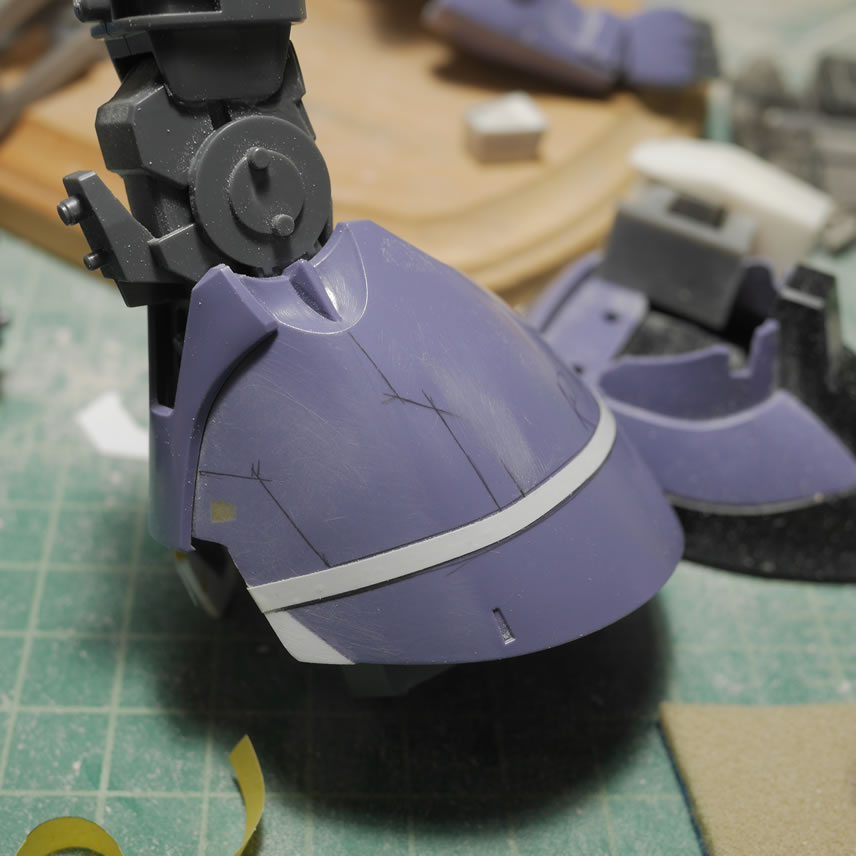
The detailing done, or so I had thought, I took some comparison shots with the OOB Dom leg.
Once primed, all the off colored bits tie together and the scribed lines really pop. I also drilled out some detail bits that I beveled slightly with a rounded jewelers grinding bit. Looking at more reference pictures, I saw that the back of the legs were also different, so I’m currently in the process of fixing that with the glued in styrene at the lower back knee area. The two halves of the legs are also glued together since the leg armor is a whole piece and not split down the middle. There is also more scribing, but that will come after I get this mod done.
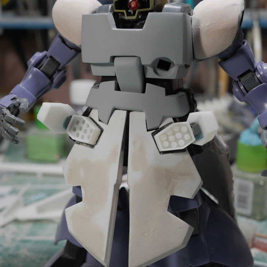
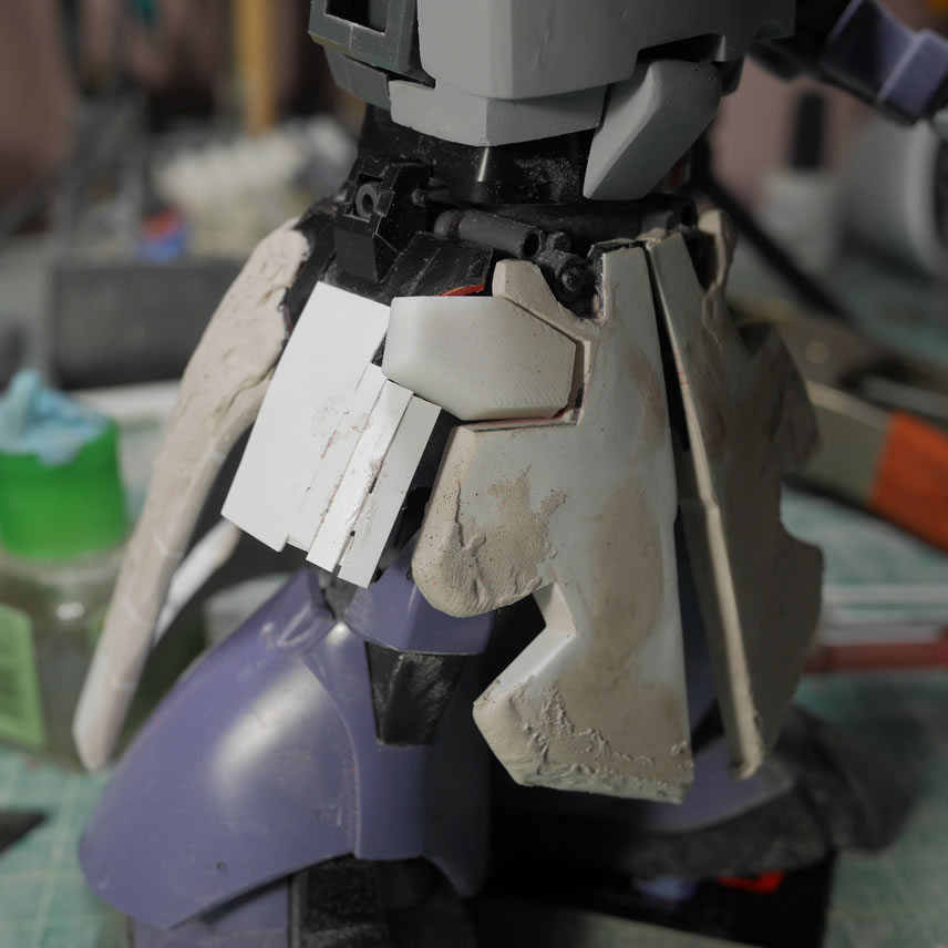
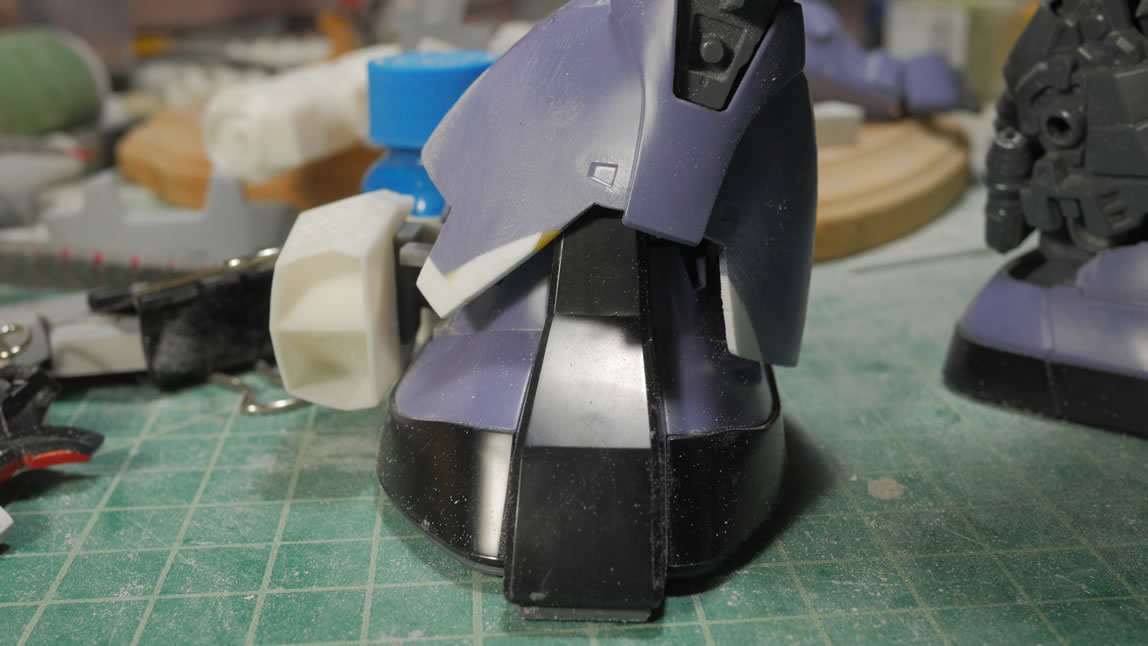
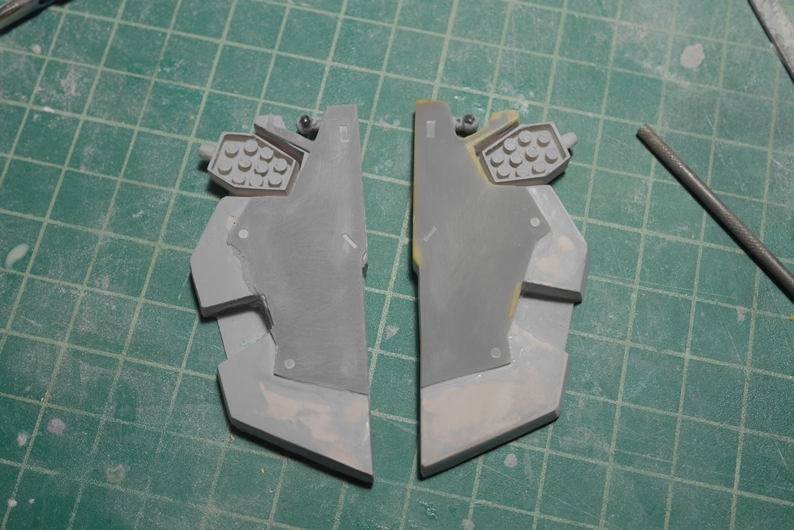
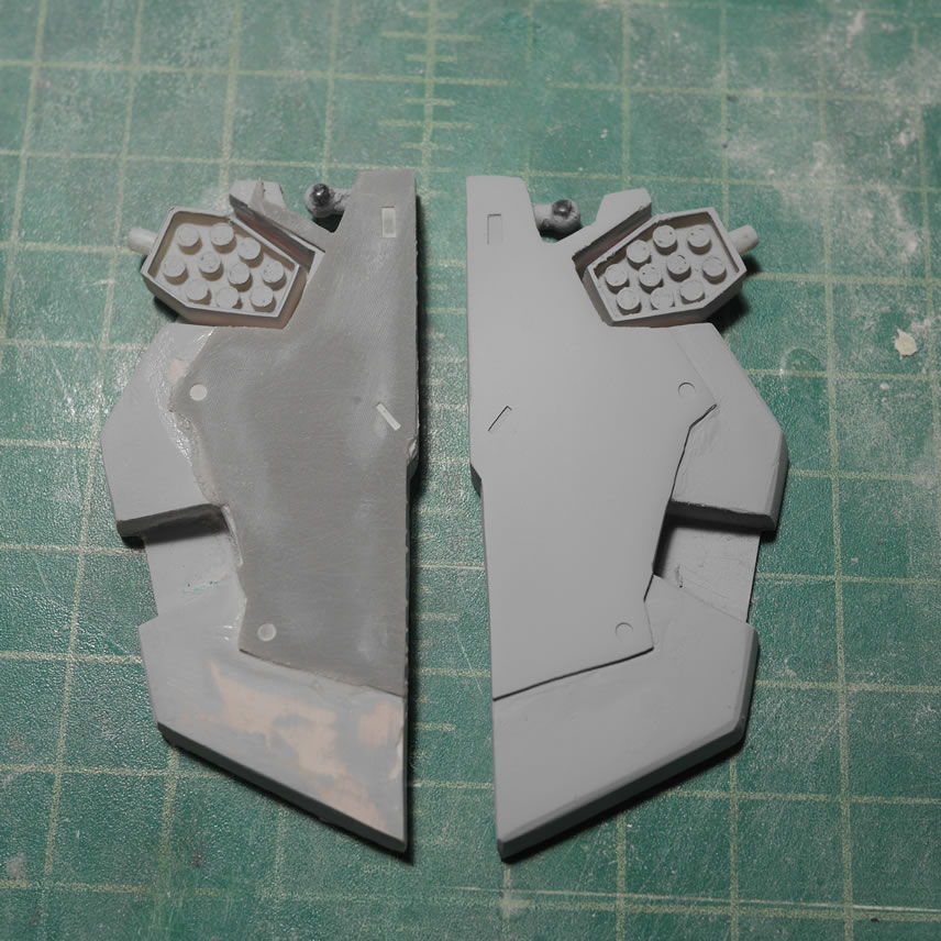
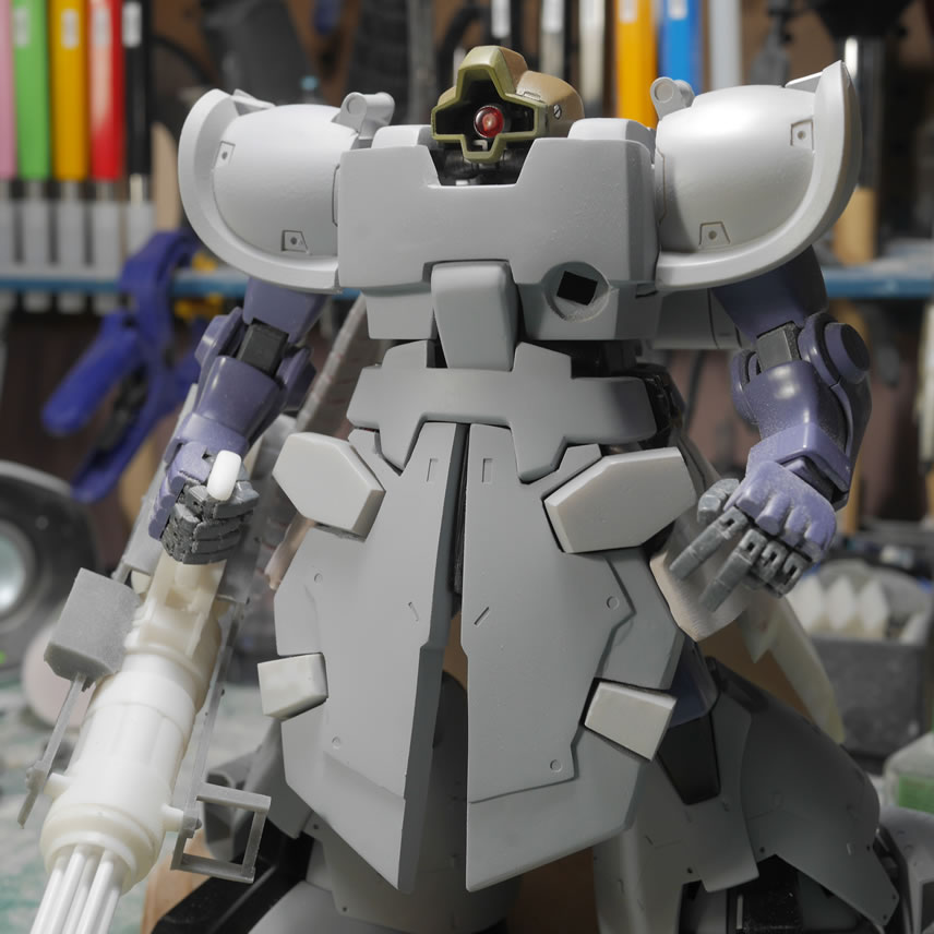
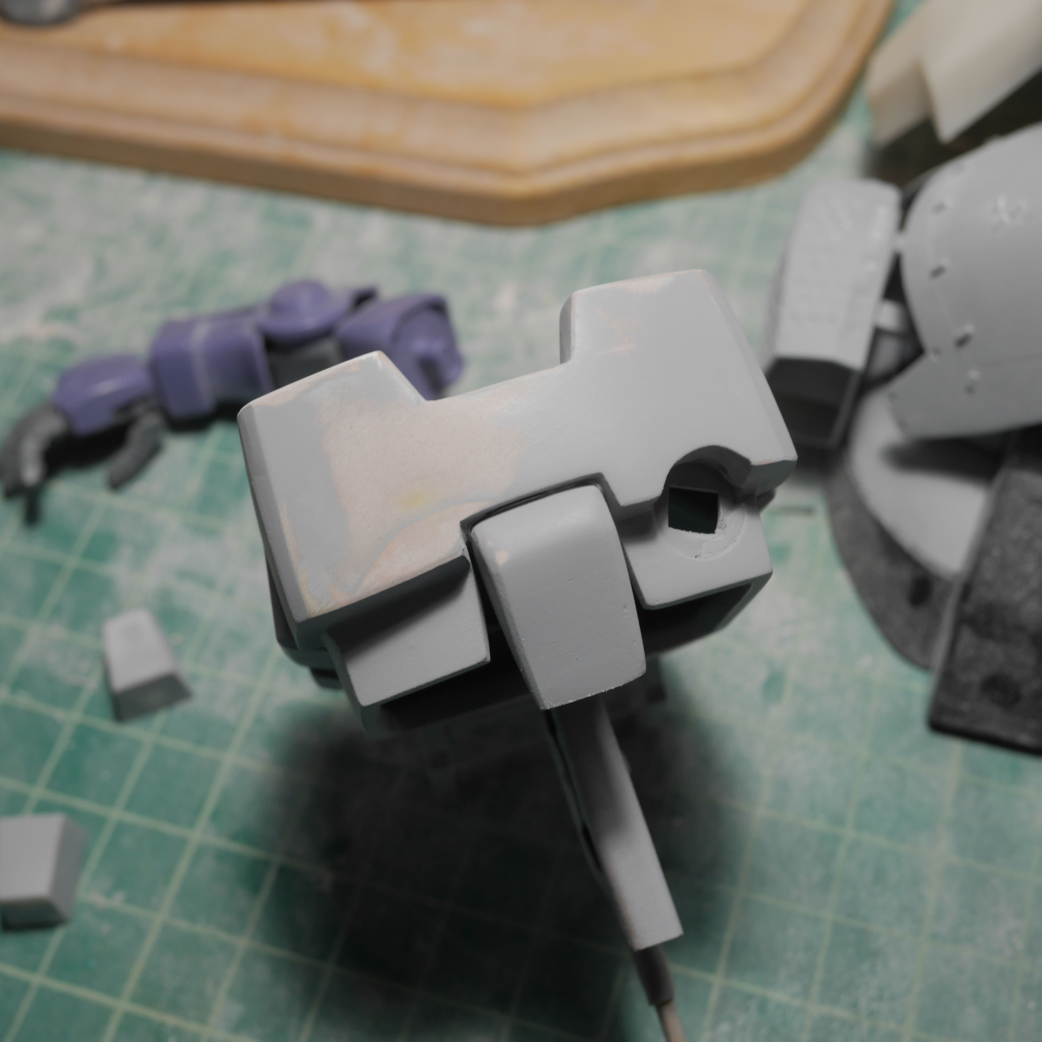
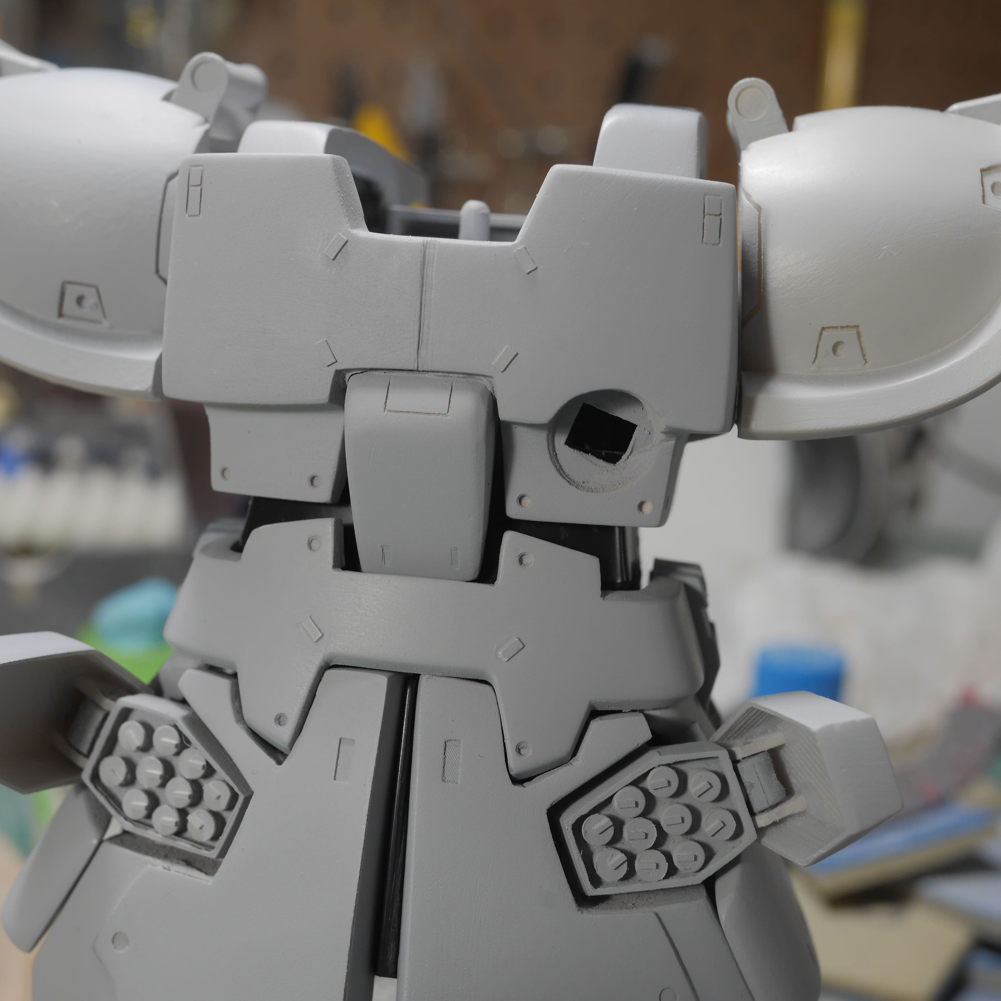
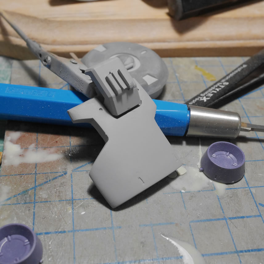
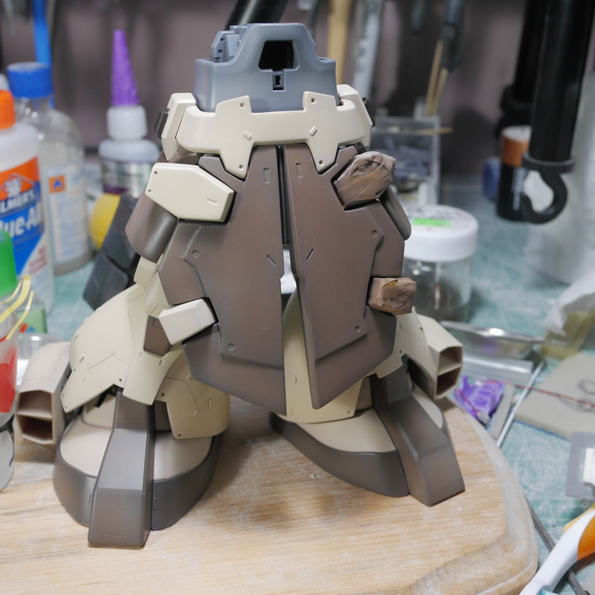
Moving back to the top half of the body, the chest needed more refinement. I start to work on the back of the chest block and just ended up gluing the front and back chest armor to the chest block. Seams need to be fixed as well as the difference in building up the two halves separately are glaringly obvious.
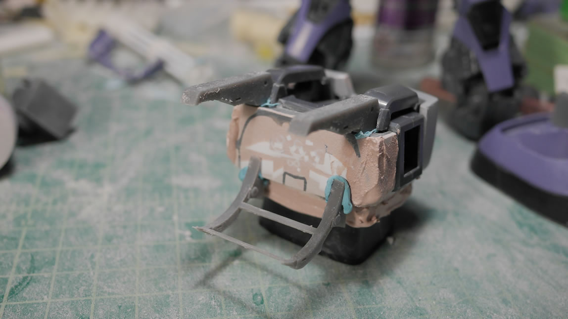
The previous posted saw the prints for the ammo drum attachment racks. Here, I’m mocking up the attachments to the back and doing a ton of test fitting to make sure it all looks correct and fits. Sticky tack is great here as a quick adhesive. The only problem is that the fit isn’t exact with the sticky tack, you get a general feel, but not the exact fit since the sticky tack has surface area of its own.
Test fit, test fit, and test fit. I also start to fill in some of the pits and pot marks on the chest block with light curing putty. In the middle of a build session, it’s tough to have to apply a putty and wait the full day or how ever many hours required for said putty to cure. Light curing putty works very well for small fixes and even small sculpting bits and doesn’t completely interrupt the flow of the build session.
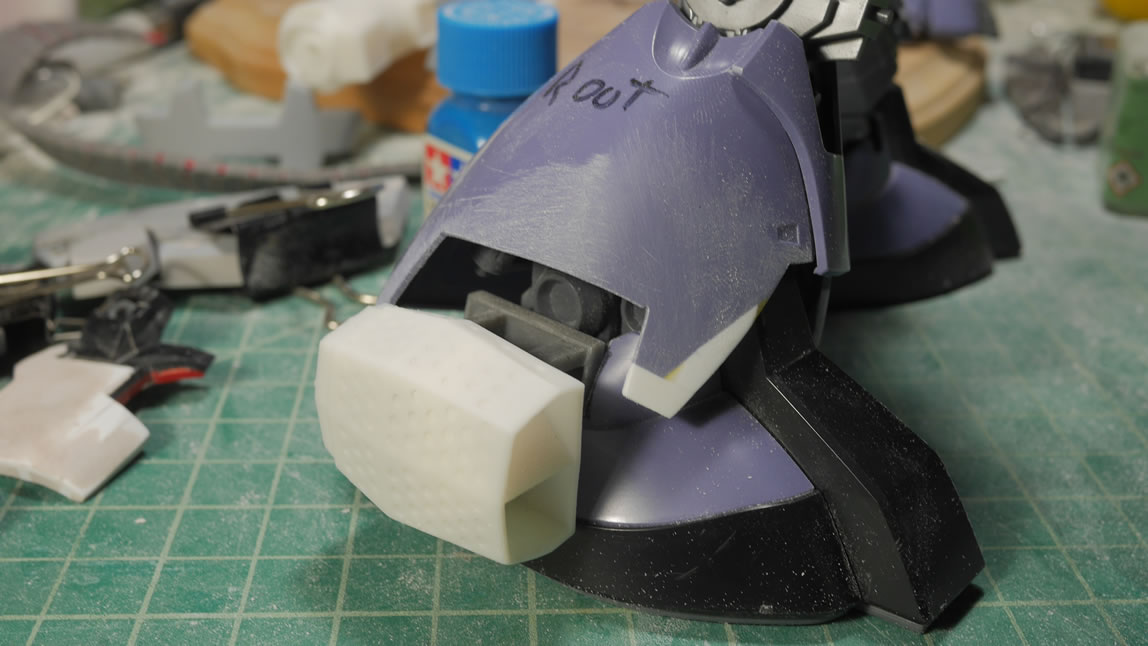
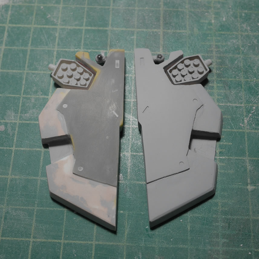
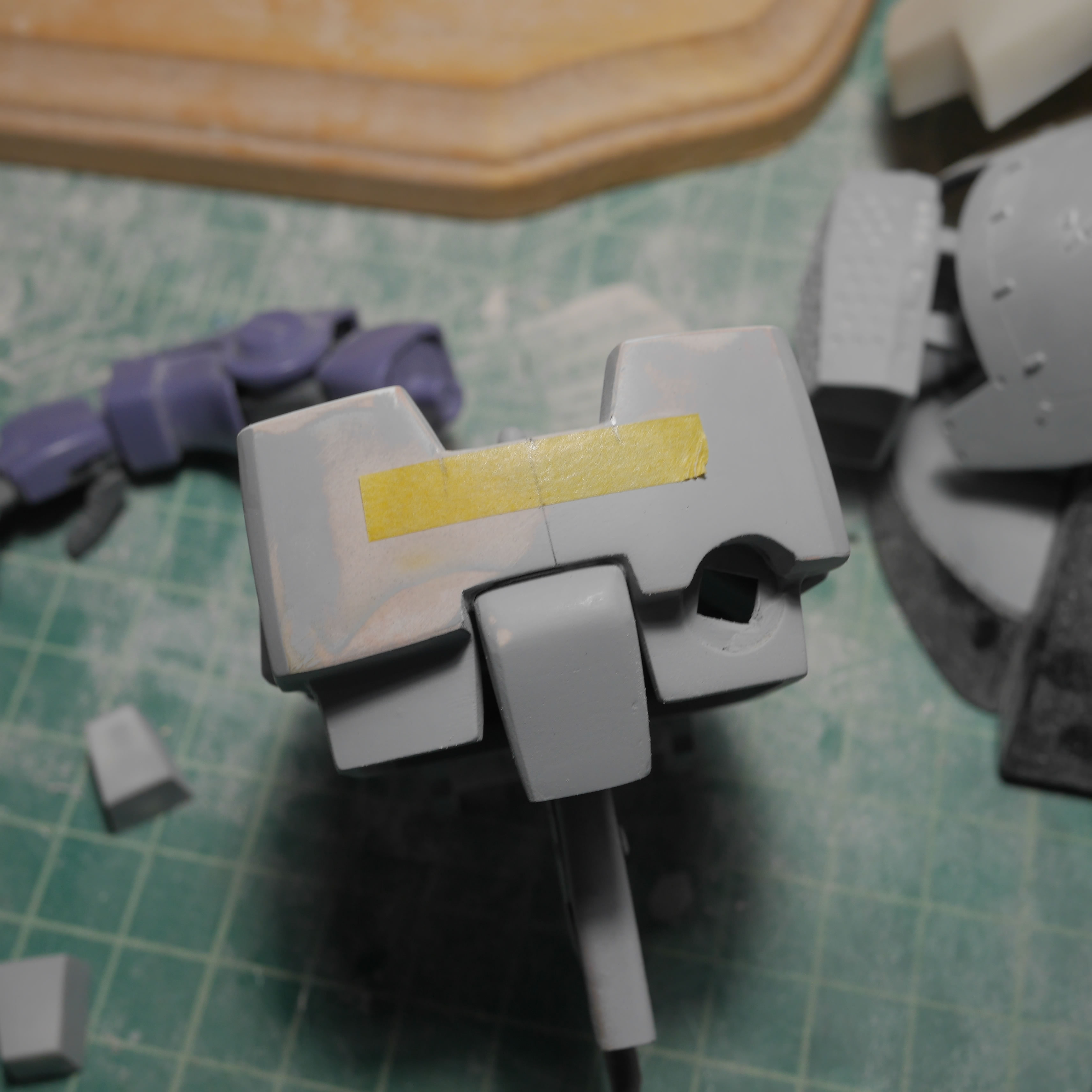
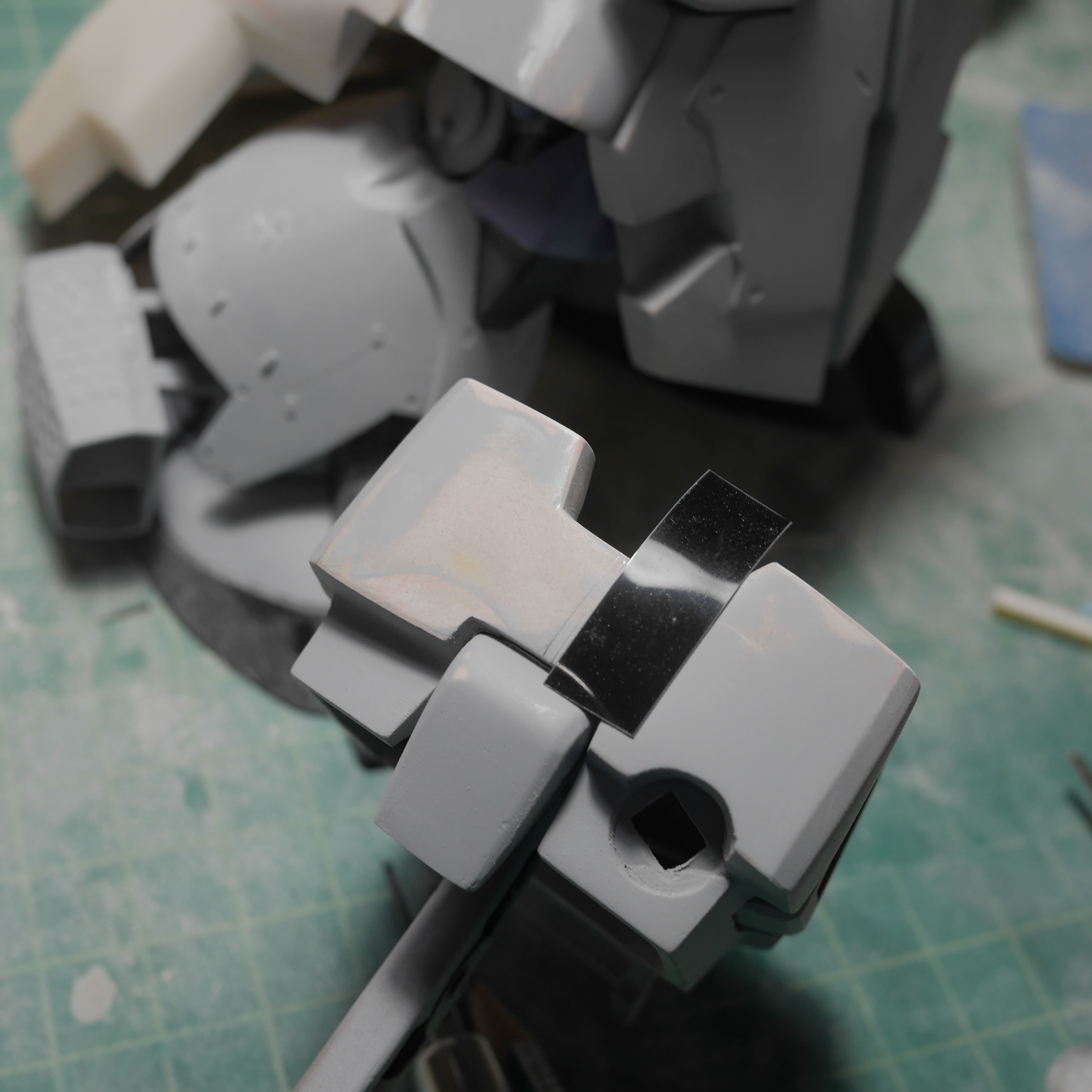
The Dom’s original shoulder straps were too rounded in comparison to the blockly Barrage style suspenders. Bondo is employed to build up the area and sanding sticks and metal files to shape it. And in the last picture, more light curing putty to keep the sanding and shaping process going. If I’m nearing the end of my build session, I’ll use a cheaper putty and just let that sit over night since I’m done building. In the middle of the build? Light curing putty all day long.
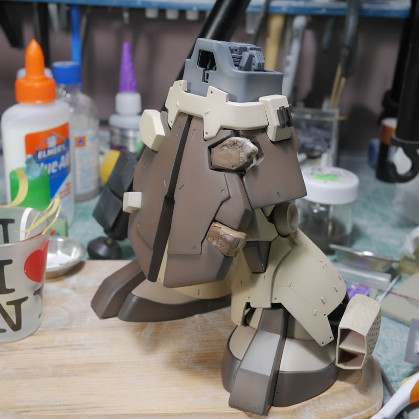
After the test fitting with the ammo drum and the attachment bits, fit required adding plastic to the back to fill gaps and fine tune the look. I glued in some plastic strips and added some putty to fill in these gap areas. With the added size in the back, another test fit is done to check the fit and gaps.
The following day, the back bit is sanded, puttied, and sanded to shape everything. Test fit, test fit, test fit.
And more detail sanding and light curing putty work to get closer to the final sculpt of things. Once satisfied, the lower attachment piece is glued into position.
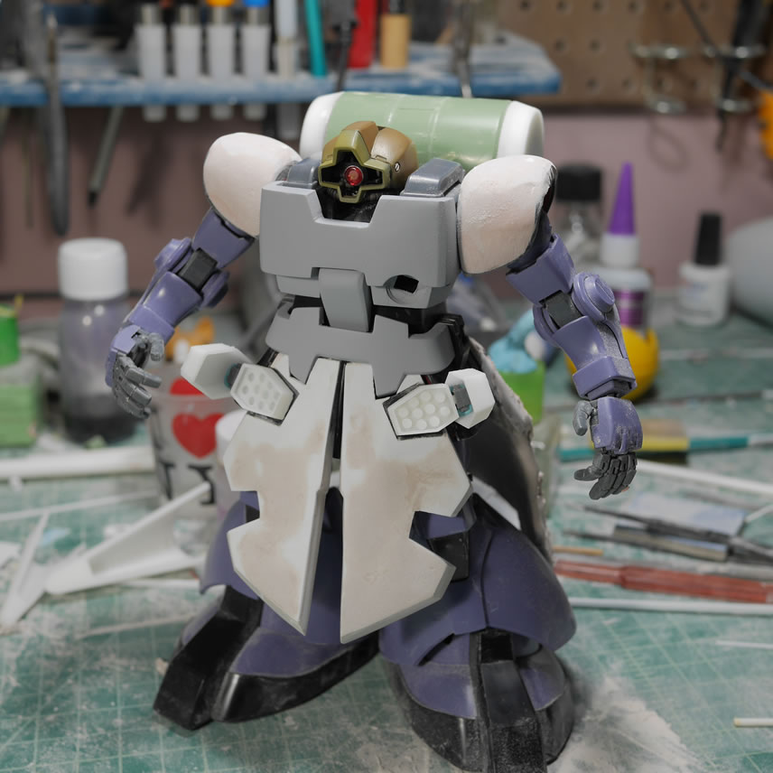
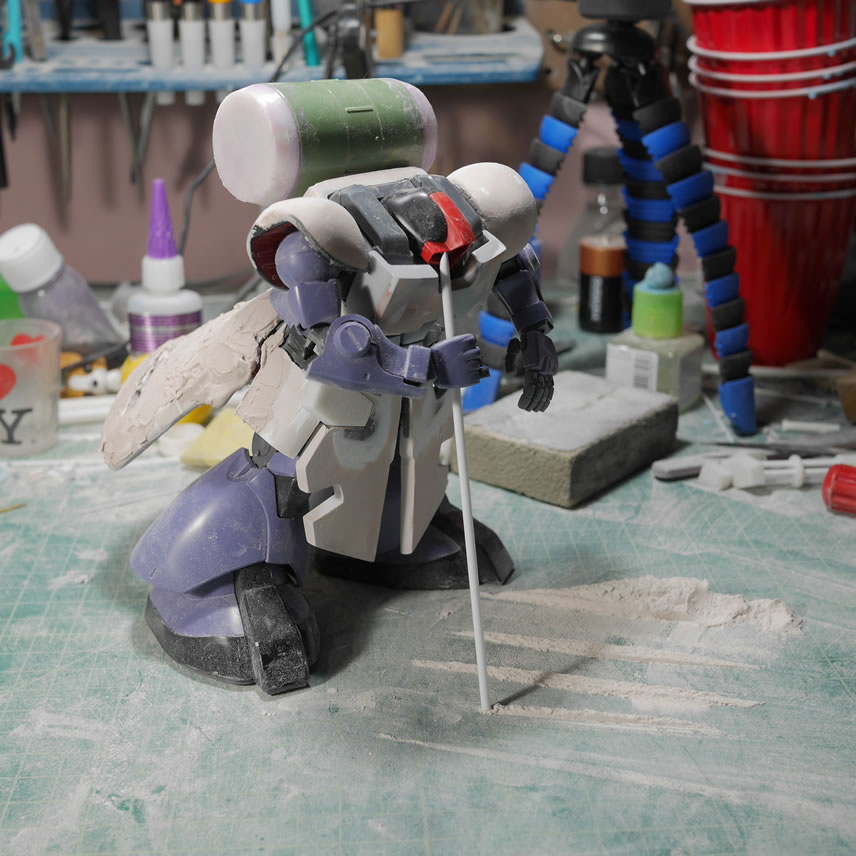
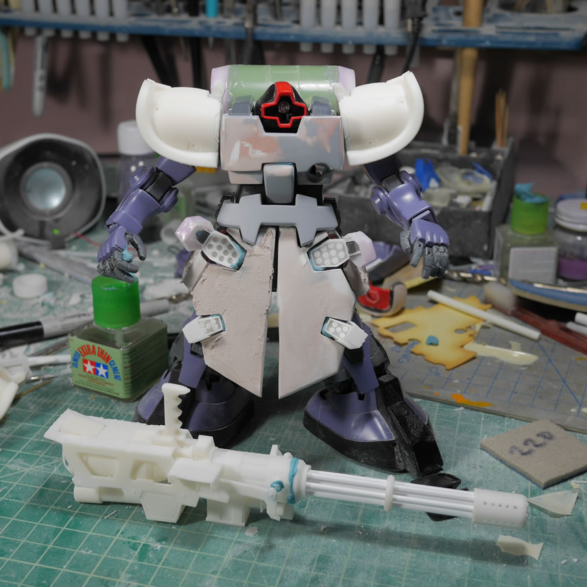
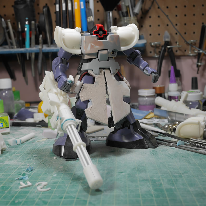
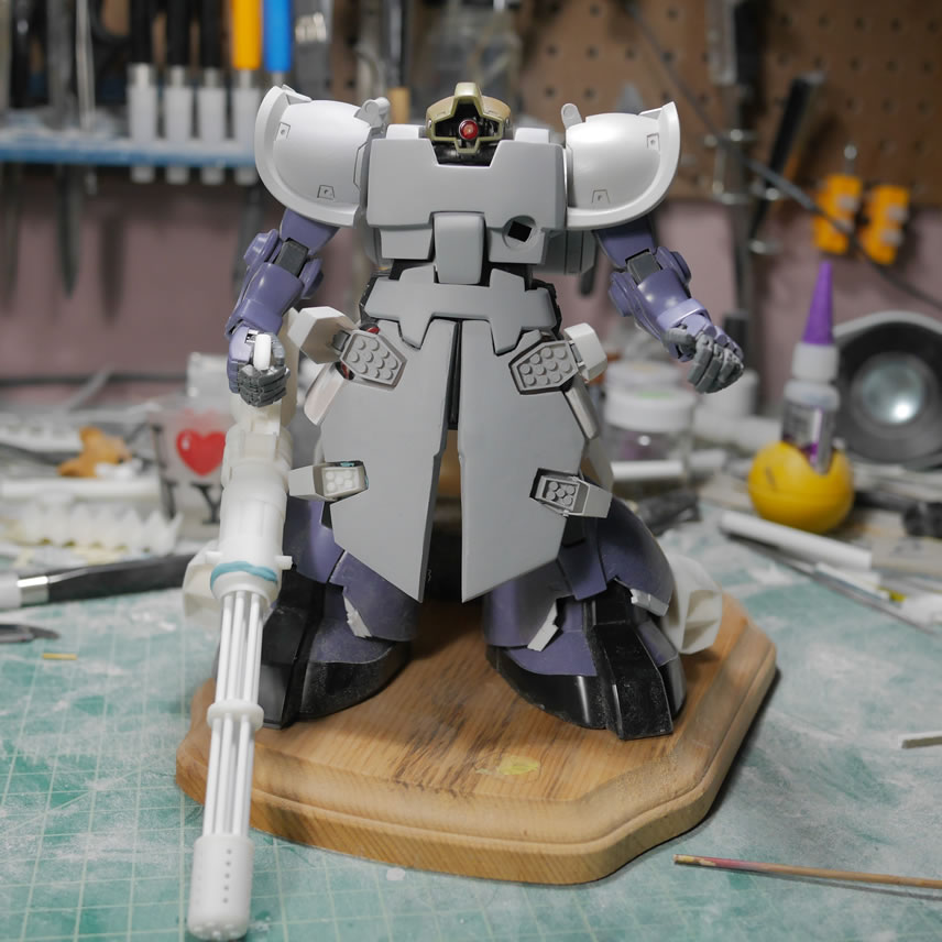
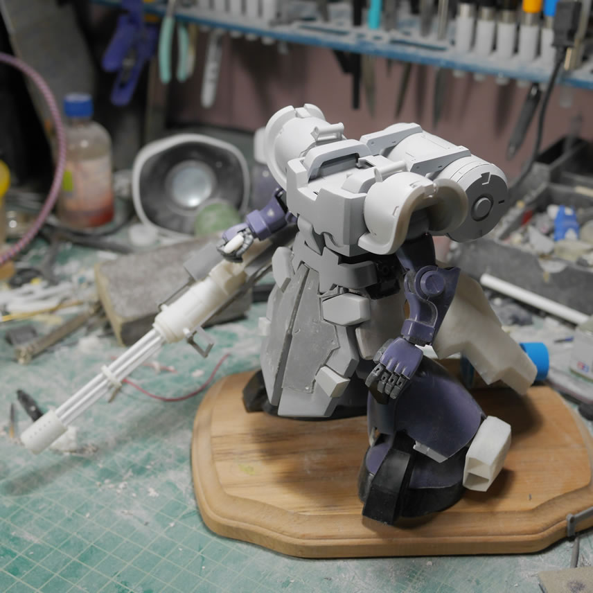
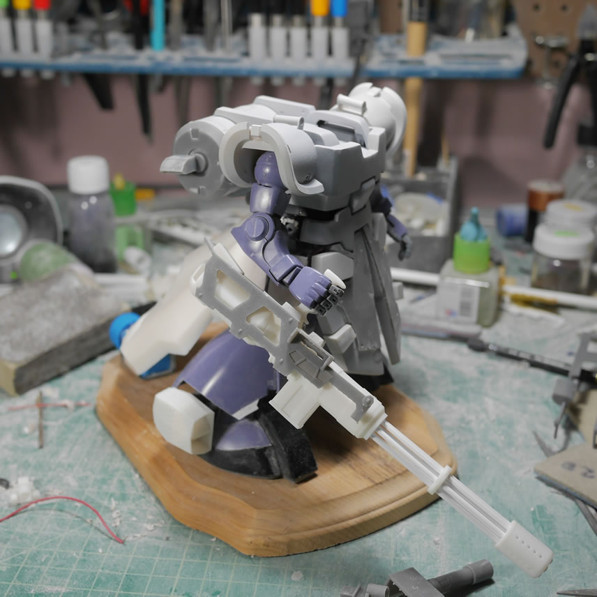
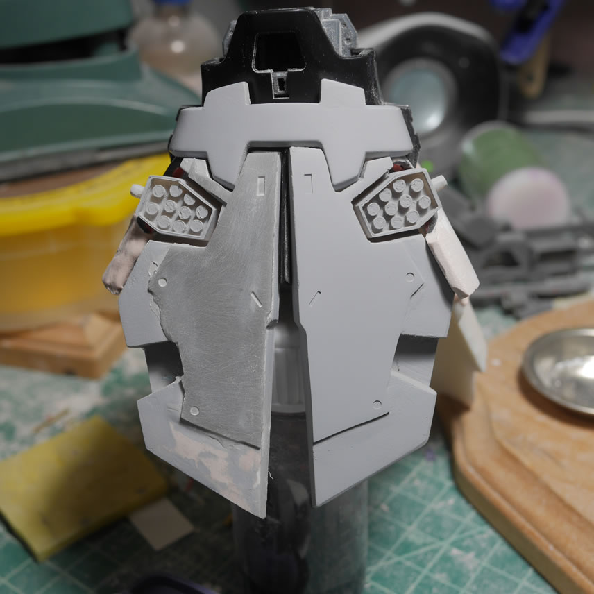
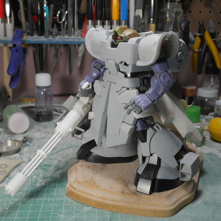
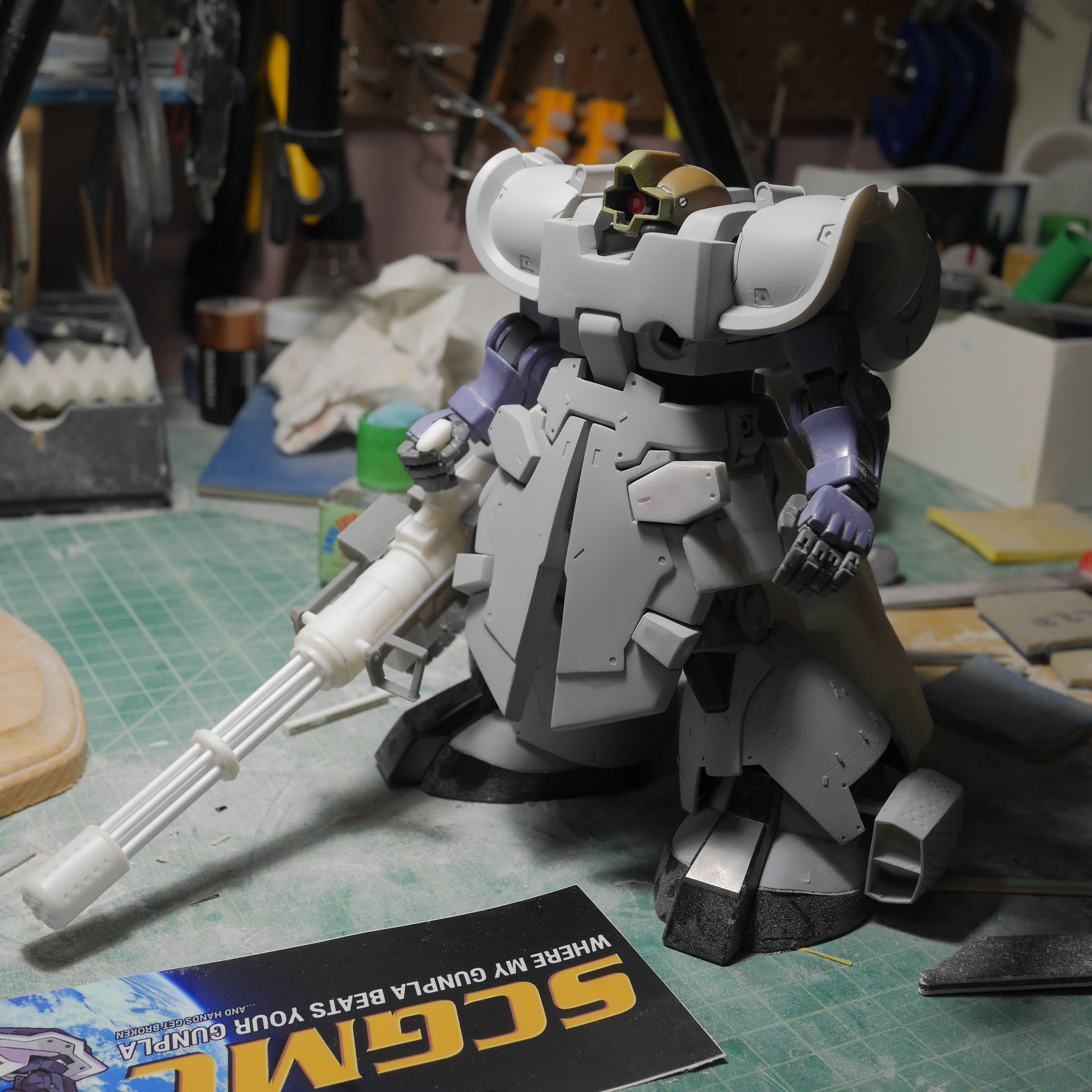
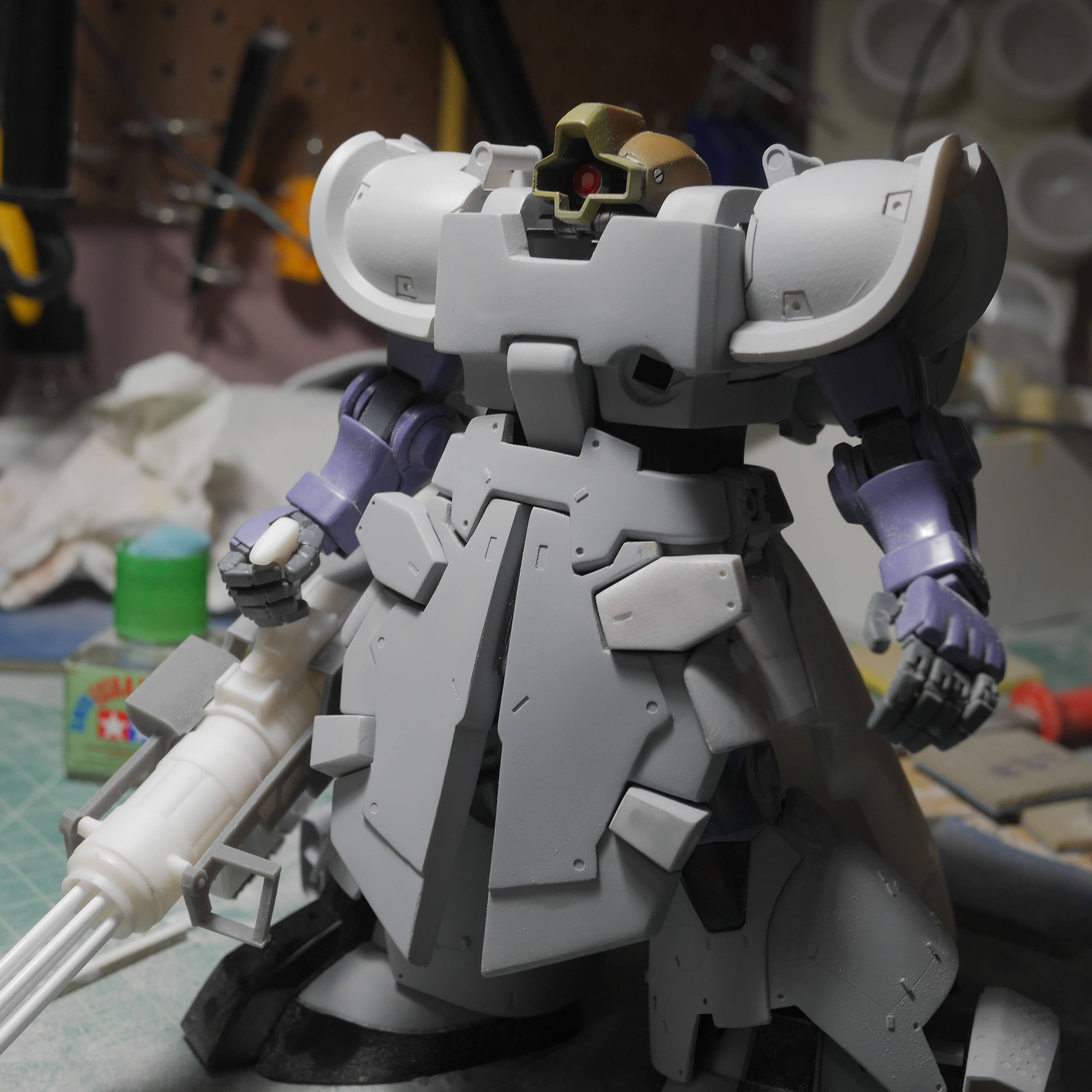
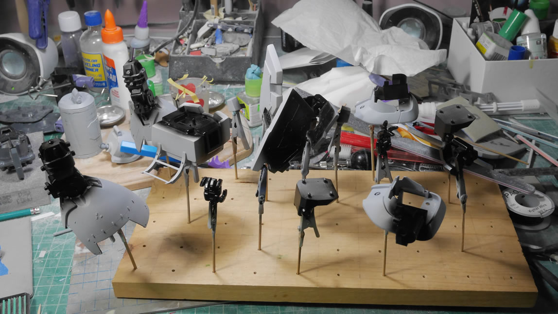
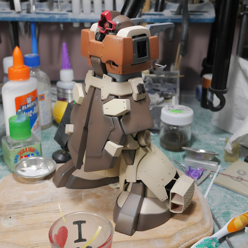
Another quick dress rehearsal with most of the principal parts to make sure everything is still fitting together. Working on small sections at a time, it is easy to forget the big picture, and it is always good to revisit that big picture. Plus, it works as a nice story piece once this is finished to watch the progression as a whole.
Moving from the upper torso, we go down a level to the front skirts. The back side is sanded but not polished and finished since it is only a surface to glue a plastic backing. The backing will be where the missile pods attach. And I can also easily scribe the surface as well as easily glue styrene details to the plastic. Glueing to the mostly bondo works best with CA glue or even an epoxy glue. For detail work, I’d much rather use styrene on styrene with plastic cement. Paper clips are used to hold the parts together while the backing glue cures.
And I completely forgot to snap pictures of the front skirt detail pieces I designed and printed. I wanted a small raised surface with the details in the front skirt, so I designed and printed. The resin is a bit brittle and easily broke, but once glued, I can fix everything in post (later).
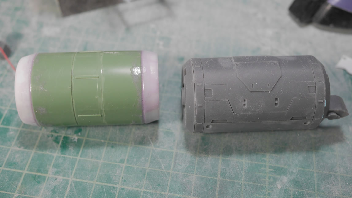
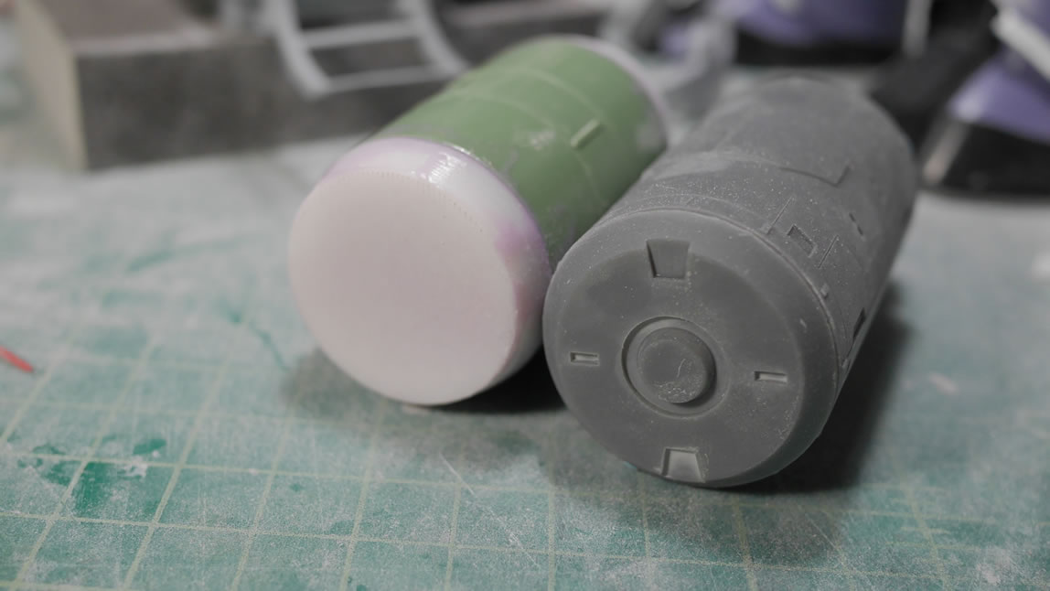
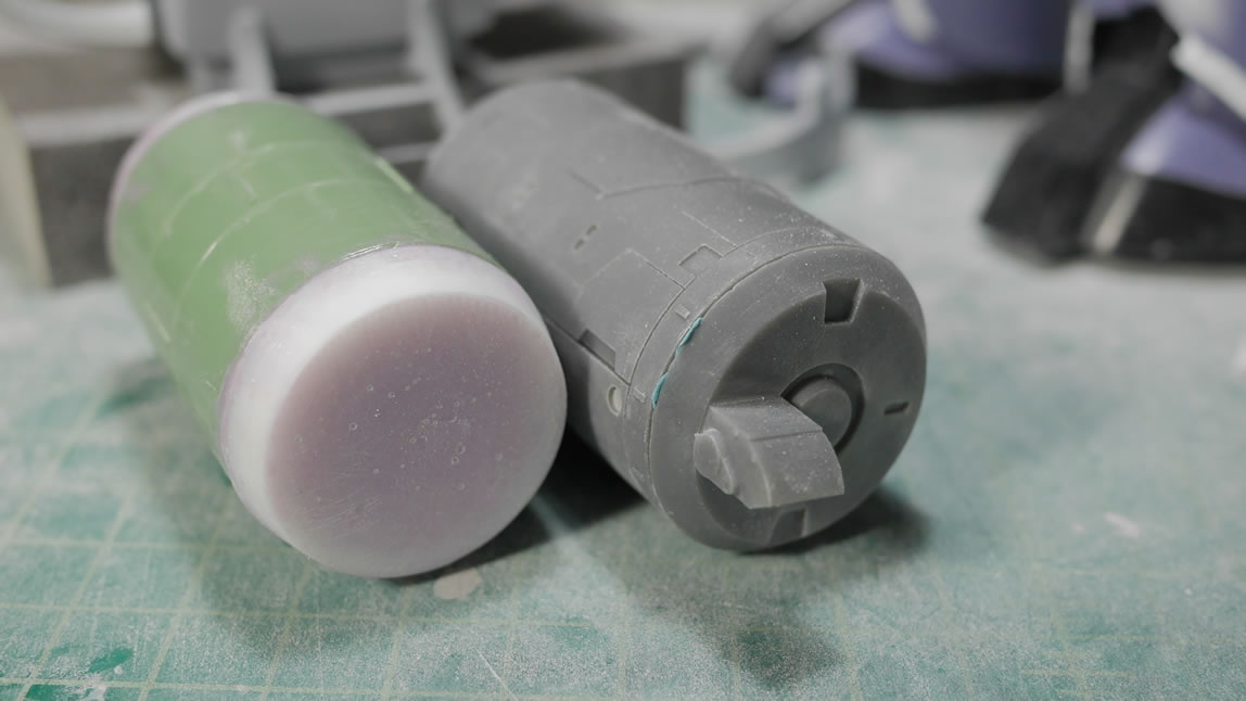
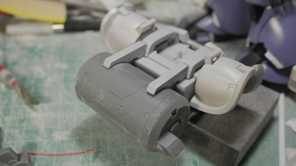
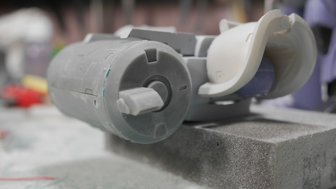
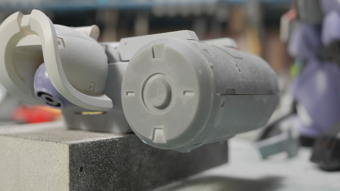
Again, as I get more familiar with the 3D design software and how my printer works, I’m more comfortable creating things. This time, I’m redoing the ammo drum. Here is the drum compared to what I built first. The fit with the attachment racks is perfect as the measurements of the original drum went into making the new and improved drum. Details such as the ammo port as well as all the surface scribed lines and raised surfaces. I did run into a problem when I raised the surface on the top and bottom. The lower attachment bar from the body to the ammo drum did not account for the small raised surface, so the fit was ruined. I had to redesign the ammo drum to remove the bottom raised surface and create an embedded surface instead.
Once that was done, the drum was reprinted and more test fit sessions to check and recheck things. Everything is looking pretty good here. I’m still debating on how I want to finalize the attachment of these pieces. I was thinking magnets. That will help make things transportable. But gluing everything down is always a good option.
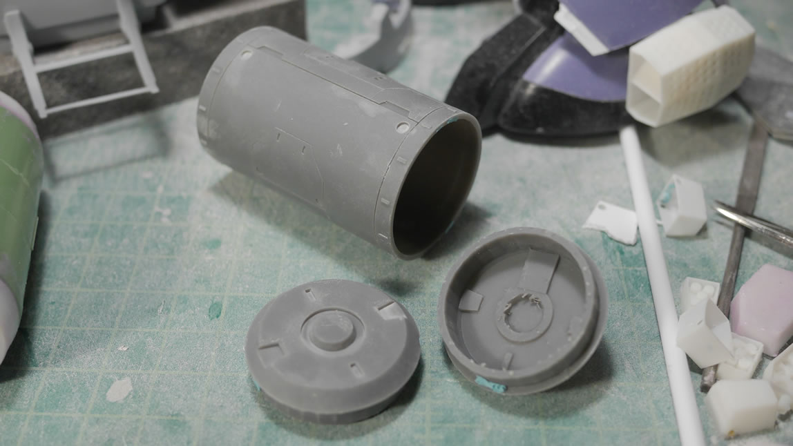
The drum was printed in 3 pieces. Resin is expensive, so it is ALWAYS recommended to design with hollows. The rear skirt is a design that is bad and not hollowed, so there is a great deal of wasted resin that makes the part way too heavy. I really should redesign that skirt piece, but I don’t want to; I’ll worry about this on the next project.
More parts are getting primer to check for defects and just to level out the colors. Primer makes me feel like I’m progressing. Another full test fit session to get back to looking at the big picture.
These test shots were taking at different points in the build. The front skirt details are glued, the operating of the missile pods was checked. And another print of the gun frame was redesigned slightly because the first print started to warp and the break. The walls were too thin. I went back to the Blender files and modified the design to thicken areas and just have a cleaner print using all the techniques I have learned since my first print of the frame.
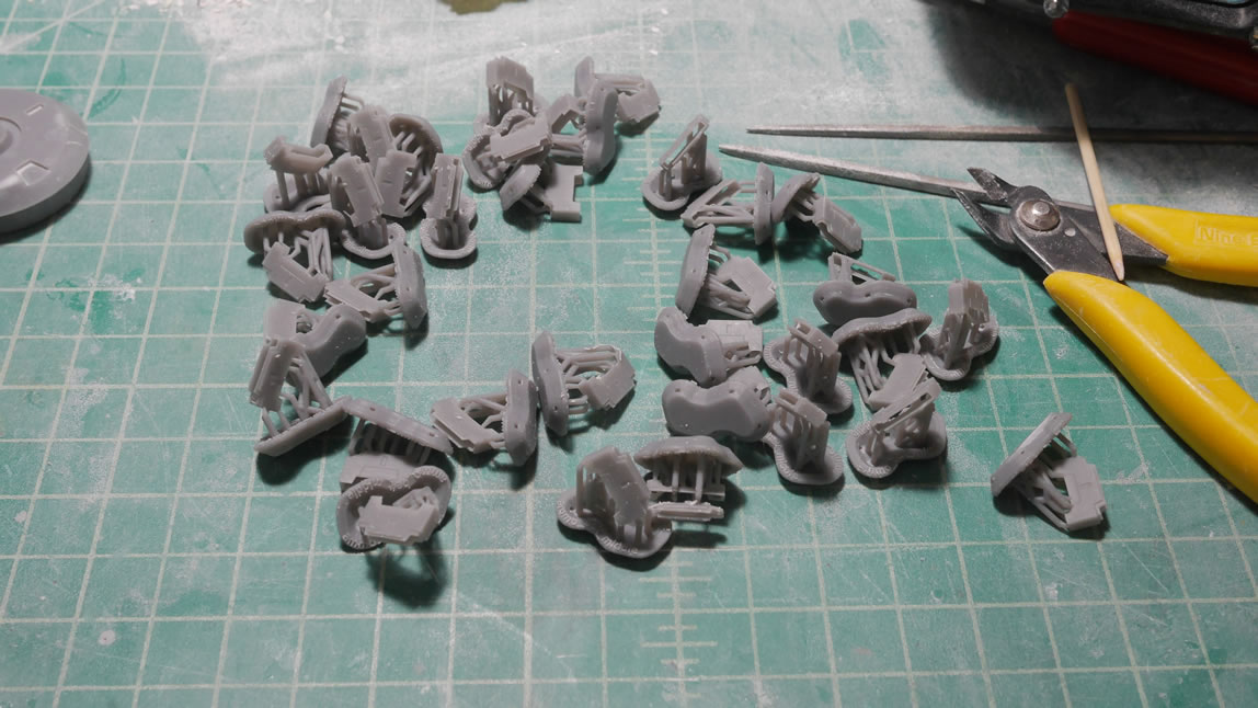
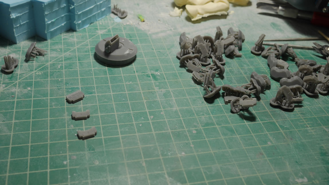
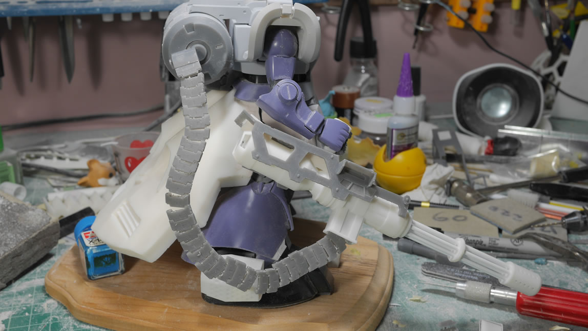
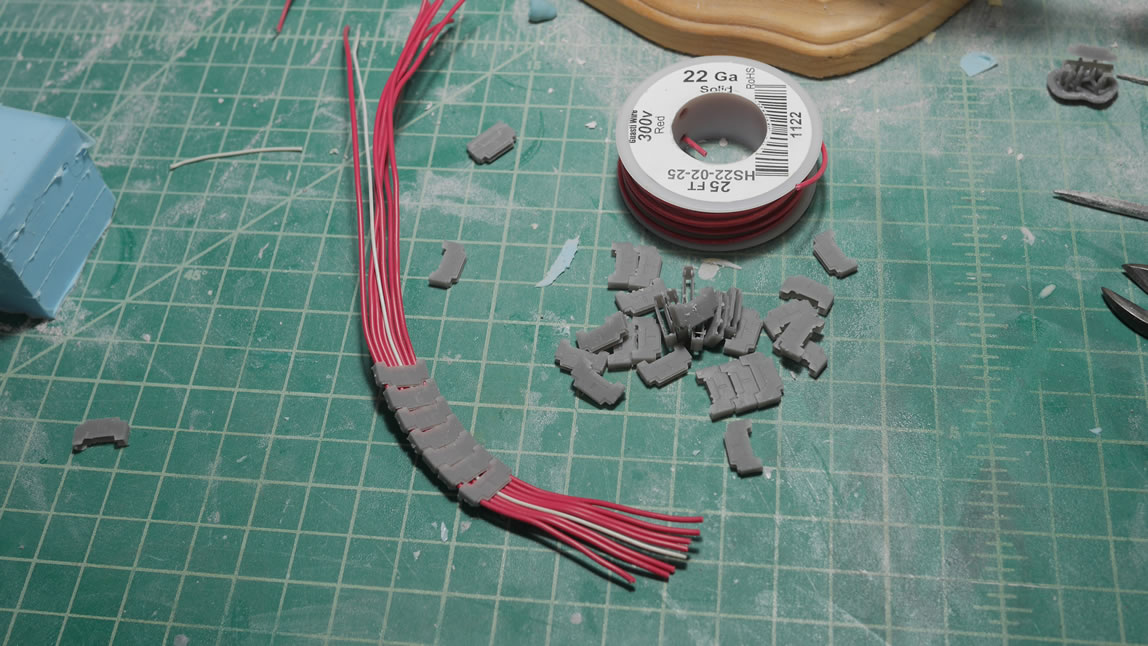
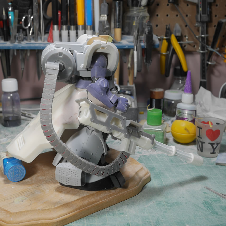
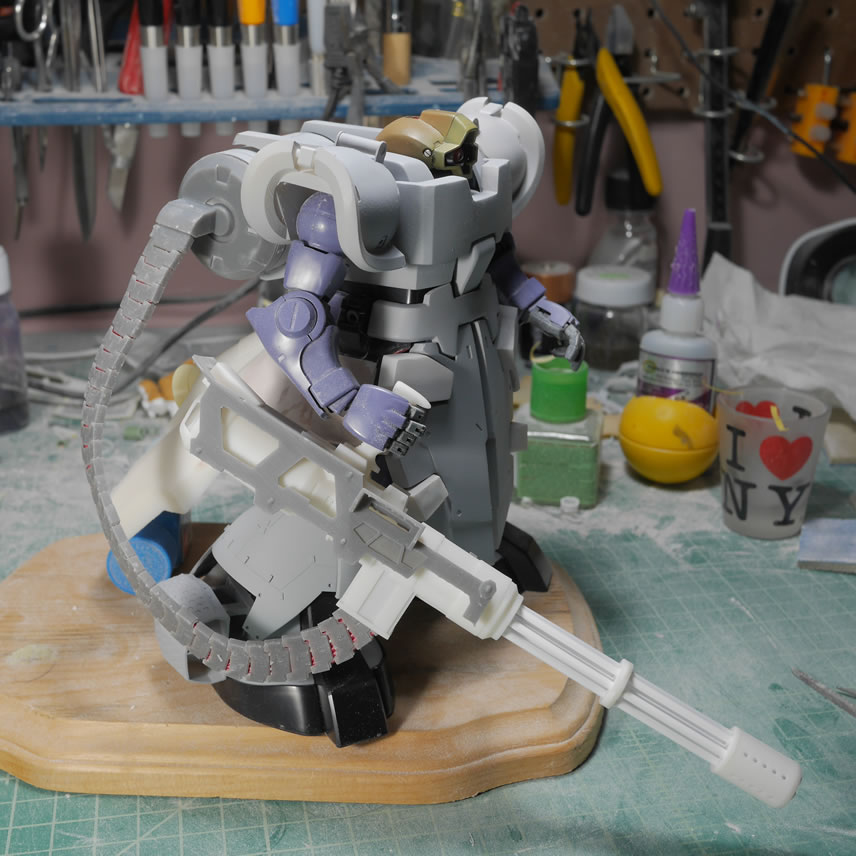
Next up, the ammo belt. There are a bunch of aftermarket ammo belts made of plastic and metal. Those belts don’t have the level of detail I want, so I designed three ammo belt pieces; the top attachment to the ammo drum, the middle link, and the end piece that attaches to the gun’s ammo port. I put a decent amount of detail into the design and some of the details don’t show up correctly since the print is so small. But I ended up hollowing and printing 30 middle links as well as one each of the front and end pieces. The front piece completely failed to print correctly, but this isn’t a big deal since that front piece was only meant to have an additional internal area as a wire stop. I designed the belt pieces to be interconnected with a wire so that I could flex and twist the belt as needed. The first test fit used one 24 gauge wire to hold things together for a quick, yet very flimsy test fit. I was really only checking for length and actual fit at the end points to the ammo drum and gun ports.
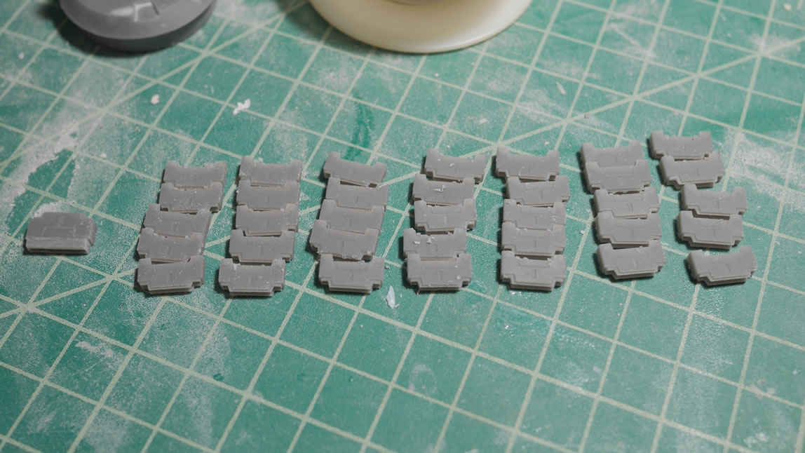
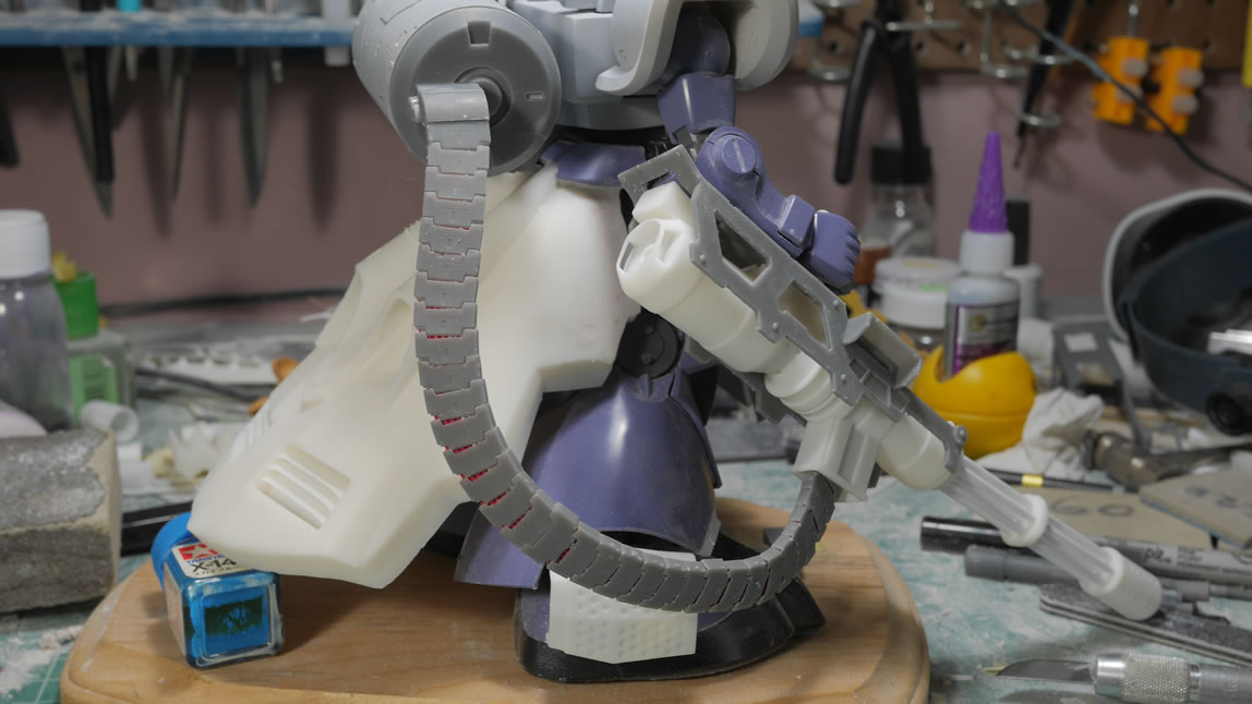
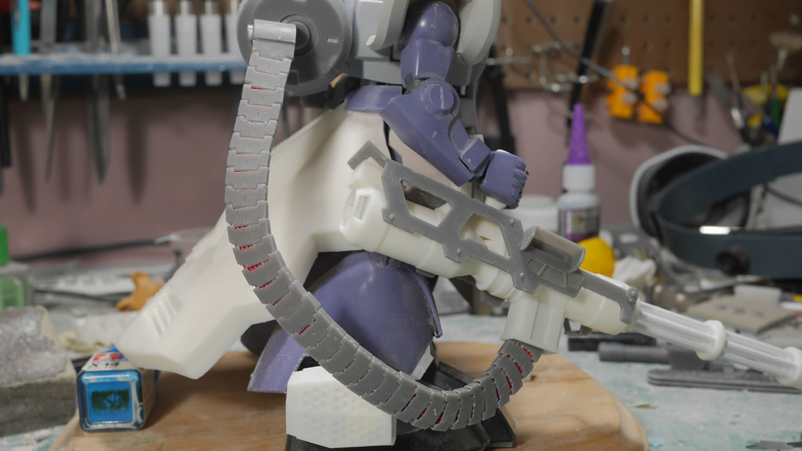
I ran out of the 24 gauge wire, so I went with 22 gauge and that worked better than the 24. It fit snugly so I do not need glue to hold the middle pieces in place and it retains flex and twist motion. I will glue to first and last end pieces. With the wire stacked into a flat belt; the ammo pieces are fished over the belted wires, the whole assembly is test fit with the drum and gun and everything looks pretty damn good. I just need to clean up the belt and get it primed.
The odds and ends are just build areas that didn’t really fit anywhere else in this post. The original design of the shoulders had a indention. This is attributed to my novice knowledge of the 3D design program and how to do rounded pieces like the shoulders. But it’s not really a showstopper as I can apply some light curing putty, sand, prime, and the shoulders are rounded with very little muss. Fixing things in post.
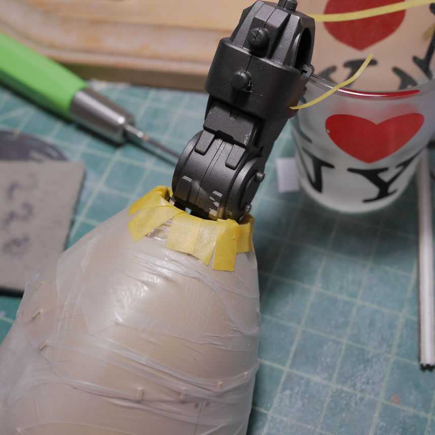
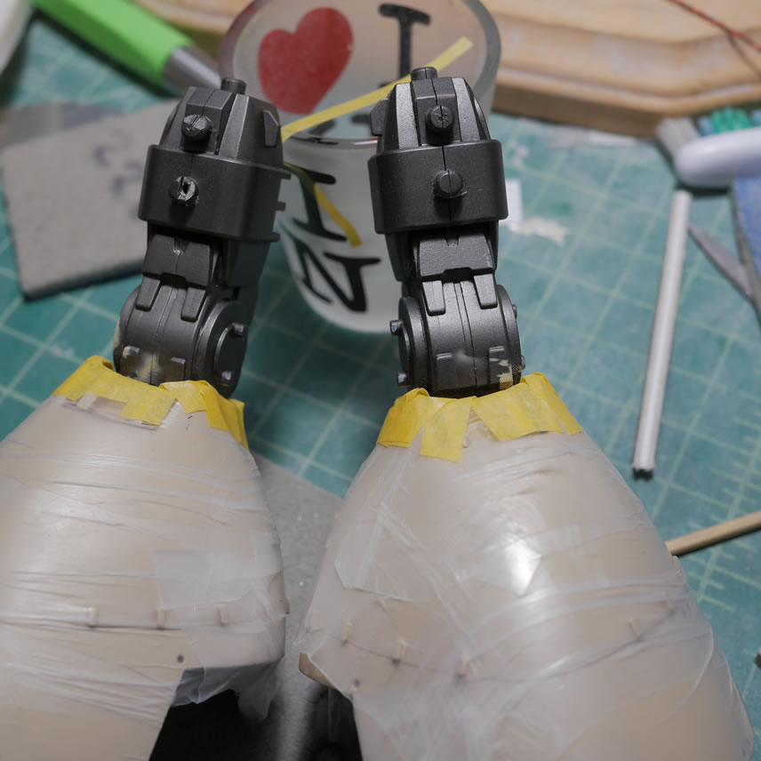
The legs saw some glue for the frame pieces. Since the rear skirt is quite heavy, I glued the legs which will help support the rear skirt. Once everything is done, the lower half of the kit will be completely fixed posed and glued together. I plan on keeping the mobility of the upper torso, but those plans may fall the pieces as the gun is also heavy even though it’s hollowed, but compared to the left side, it’s unbalanced, so the upper torso may also see a solid glue joint.
Hopefully the next update won’t take so long and I start getting things completed. There is a ton of build work, but I am getting closer to the fun paint stages.
June 3, 2019: I had a pretty productive weekend for the project. This is mostly cleanup work; but there was a small bit of leg detailing that I didn’t quite complete before my last update. I also want to ramp up the progress since I want to be finished by the end of the month. Who knows if that’ll happen. But goals. I’m going to do shorter walls of text, but try to do weekly updates from here on out. Famous last words.
Returning to the leg, last week I glued in a piece of plastic as a structure base for more bondo. Here I have the bondo added to the back of the legs. I’m also reshaping the back legs to get rid of the small point from the OG Dom’s leg See the last picture in this set for comparison. This meant rescribing the detail line as well as sanding away plastic details that I had already added. This happens when you make mods. You change your mind and have to start erasing or sanding it away only to add it back… it’s all plastic in the end. The putty cured overnight and the legs got sanded. Lines rescribed, and some light curing putty is used to help fill in mistakes here and there. A piece of plastic was cut and scribed(really hard to see until I prime it) but this new plastic piece is the new back leg cover. I filled in the detail marks at the bottom of the legs. Another line is scribed on the inside part of the leg and detail holes were drilled.
I puttied over the detail insets on the back of the legs as I wanted to add in some scribed detail. I cut some dyno labeling tape measured for length and angles. A pencil line marks the measured height of this detail. Tape is placed and a .3mm BMC chisel scribes the lines. Another two drilled out detail bits and some extra plastic plate I had cut from the previous update is glued to the surface. One leg done, now for the other.
Notice that there is a white plastic bit on this leg piece (near the hole on the right side). I had made a mistake when drilling the hole, so I needed to fill it. I used styrene glue and a plastic rod and a little bit of white putty. Once that cured, it was sanded down and the detail drilled hole was attempted again. Once that looked correct, the plastic details were glued and this leg is ready for primer. Mistakes will happen, it’s part of building process. It’s only plastic, fill it back and try again, and again, and again until you go insane or get it right – there are only two options here.
Once primed, all the details start to pop better and a comparison shot with the original leg piece shows how much has changed. And realistically, not much was done. Just a little sanding and cutting and the whole look of the leg completely changes. The legs were primed at different times because I had to wait for the plastic and putty on the mistake to cure. Which worked out as I can show the difference between the primed part and the modified multi-putty-plastic-colored look of it all.
Done with the legs I move to the front skirts. There is a crap ton of work for the front skirts. I had printed out a detail plate that I glued over the top of the scratch built skirt. The marriage of the two pieces is not perfect, so there is a decent amount of clean up and putty work. Light curing putty really speeds up this process and I was able to finish one of the skirts Saturday night. The yellow areas are the light curing putty.
As I slowly progress, I have the other skirt piece left alone for a before and after photo.
Test fit! Testing with the other armor pieces shows the areas I need to fill and build up. Once I start puttying and sanding, I keep going back to checking on the fit to make sure it a: fits, and b: looks correct. You should be able to clearly see the filled in light curing putty areas. It is just putty and sanding. Just lots of it. And as we progress, the working skirt is being built up and cleaned up. There is a bunch of CA glue residue to sand down (which is a bitch and a half to sand btw). I had done a quick print for this detail piece so the resolution lines needed to be sanded away as well. The last thing I did before going to bed was prime the piece.
Here is the comparison of the primed piece and the other skirt piece. And as always, test fit, and you should clearly see the differences in fit and the numerous gaps for the before and the after. Happy with the one side of the skirt, time to work on building up and cleaning the second skirt piece.
No progress of that other skirt piece because it would be redundant. Just mirror image the above in your mind and there you have it. Time to move to the rear skirts and work on some more sanding and shaping to fit it with the waist as well as get the correct look with the side skirt alignment. I still have more filling and sanding, but the end of the weekend crept in and I’m done for the night.
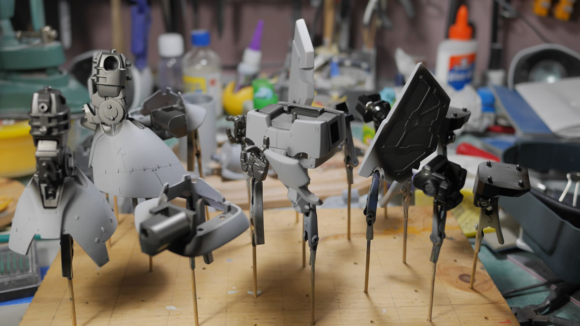
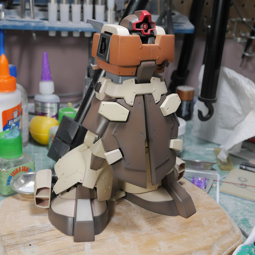
I primed more than just the skirts, I also finished priming both legs as well as the top of the feet and the vent detail. There is quite a bit of cleanup for those areas, but more primed pieces gives me a sense of accomplishment. Even more so when it’s time for another full dress rehearsal. I snapped everything I had together for some pictures. This also works to check that all the small detail work for each small subsection still work in the big picture of everything. This is getting exciting, things are really starting to come together.
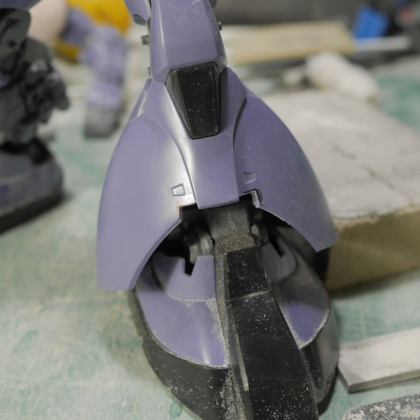
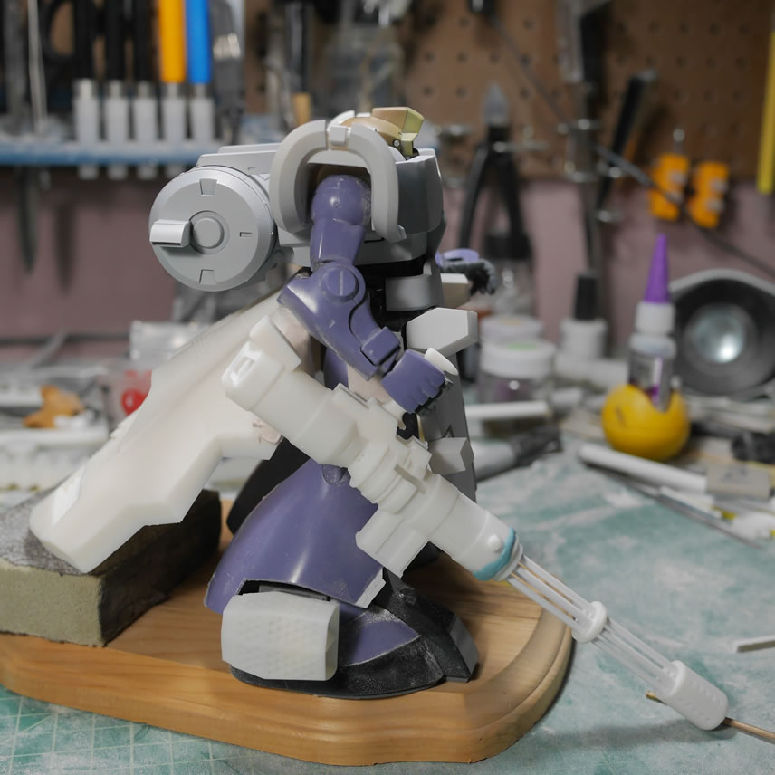
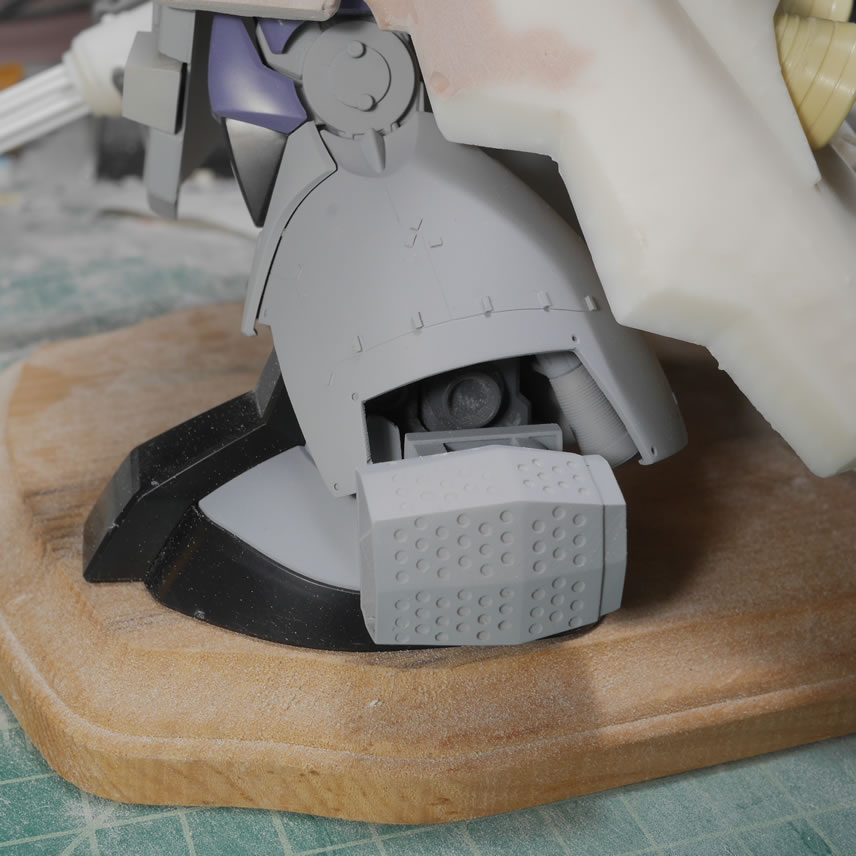
The rear skirt pretty much covers the rear leg details. But for anyone looking under it’s skirt, that’s there for ya; ya damn perv. The internal leg motor and thrusters can be seen which is pretty cool. The thrusters are modified from the original to lengthen and just beef them up.
As far as the build, I believe I have the gun and the rear skirt to finish building and soon we’ll have a fully primed project.
For shits and giggles, here are some pictures of the progression/evolution of this project from day one to now.
From the above to below (so far)
June 10, 2019: Trying to keep up with the shorter weekly walls of texts. I’ve got some pretty cool things to show for this update so there is a decent amount of meat here. We’ll start off with the front skirts. The back of the front skirts to be exact. In the first picture, this is a picture of the cricut design space software with a back skirt design drawn out. The steps leading to this was first painting the back of the skirts so that I have better contrast when scanning the skirt backs in the all in one printer. The scanned JPG file is then edited in gimp to clean it up and convert it to a transparency PNG file that is then uploaded to the design space software. Once there, it was just a matter of cutting and adding shapes to create the underskirt frame detail.
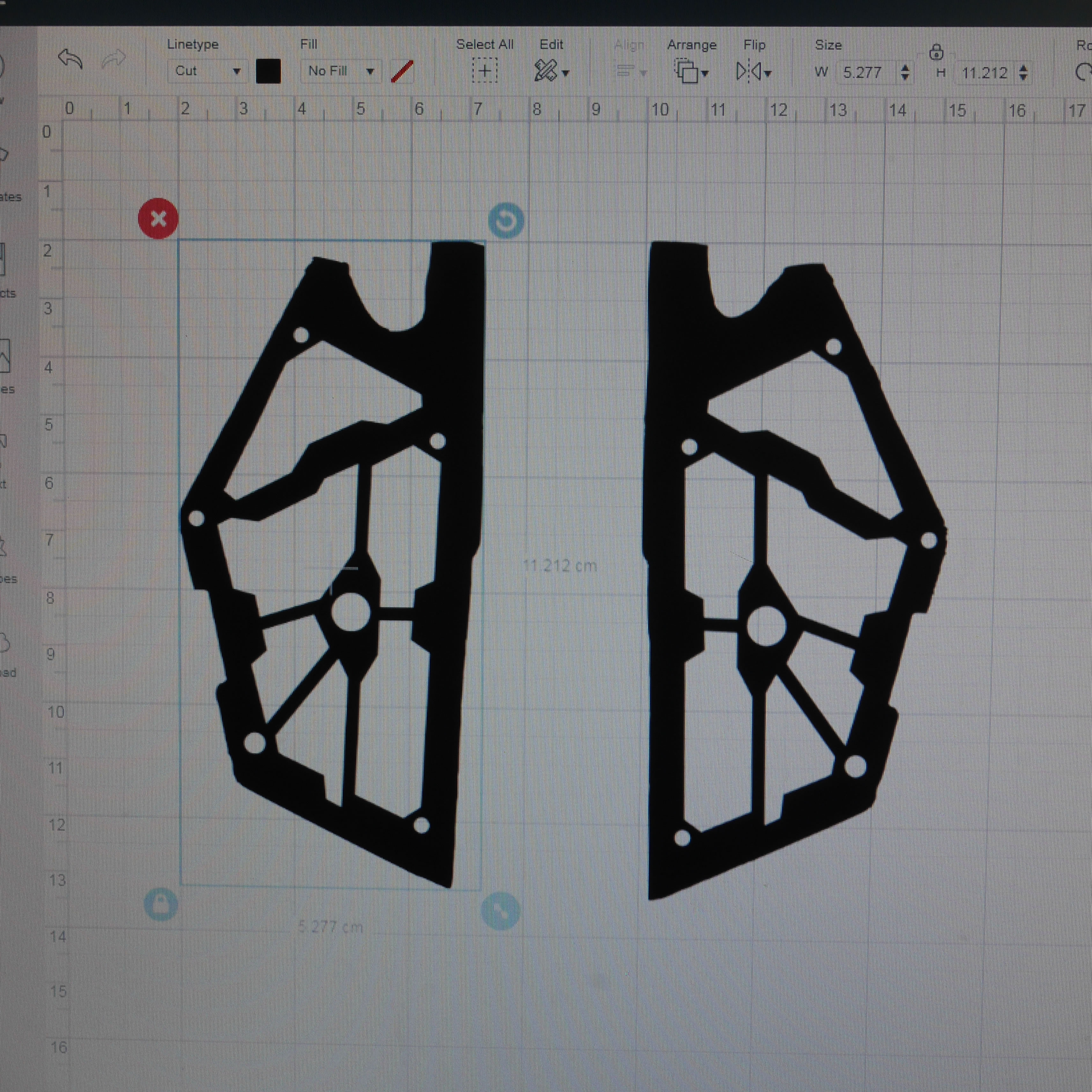
Finished with the design, I make some measurements on the real skirts and use these measurements for the image in the cricut design software. I don’t need to be exact since putty will fill in any gaps or just sanding will take care of any overlaps. But I want to be as close as possible.
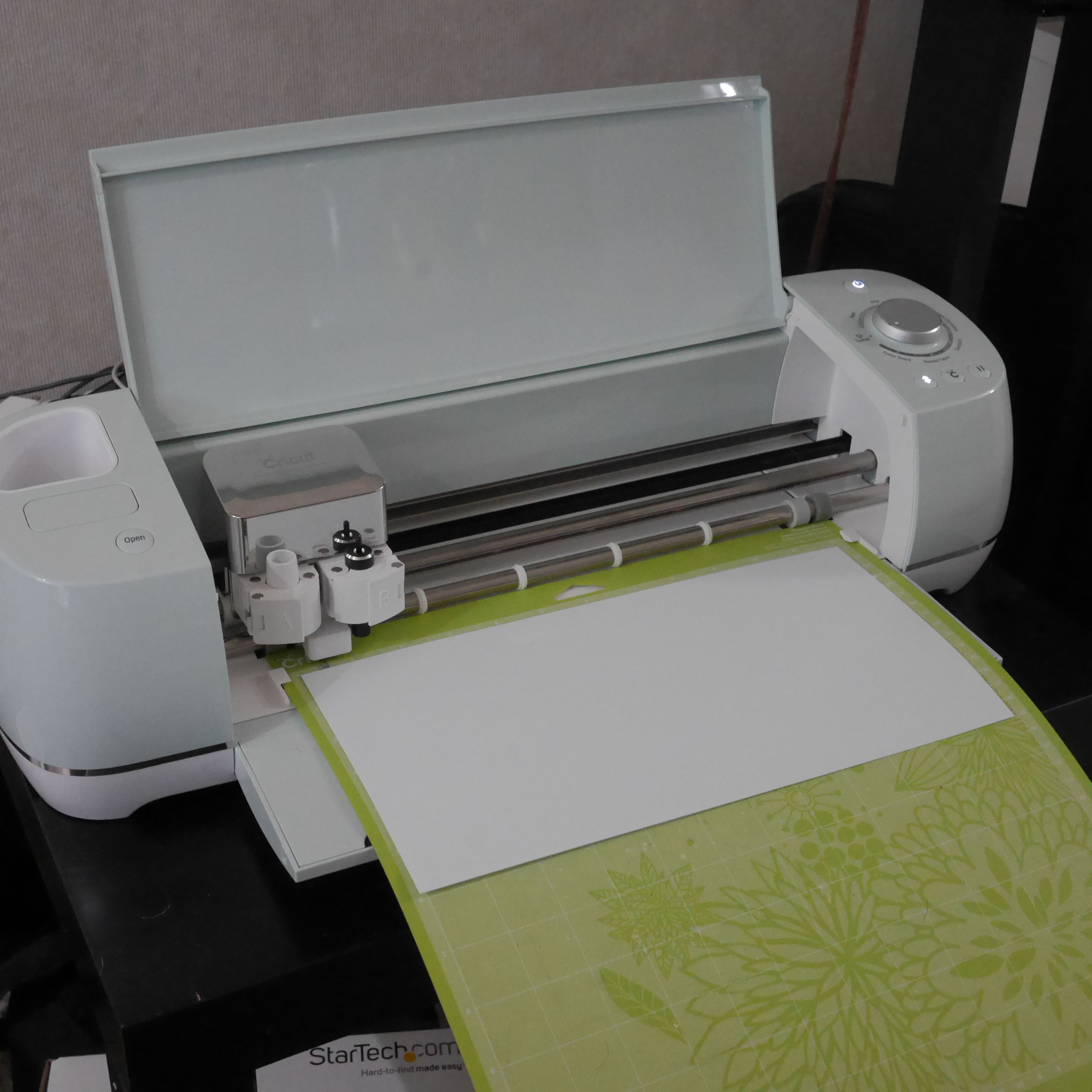
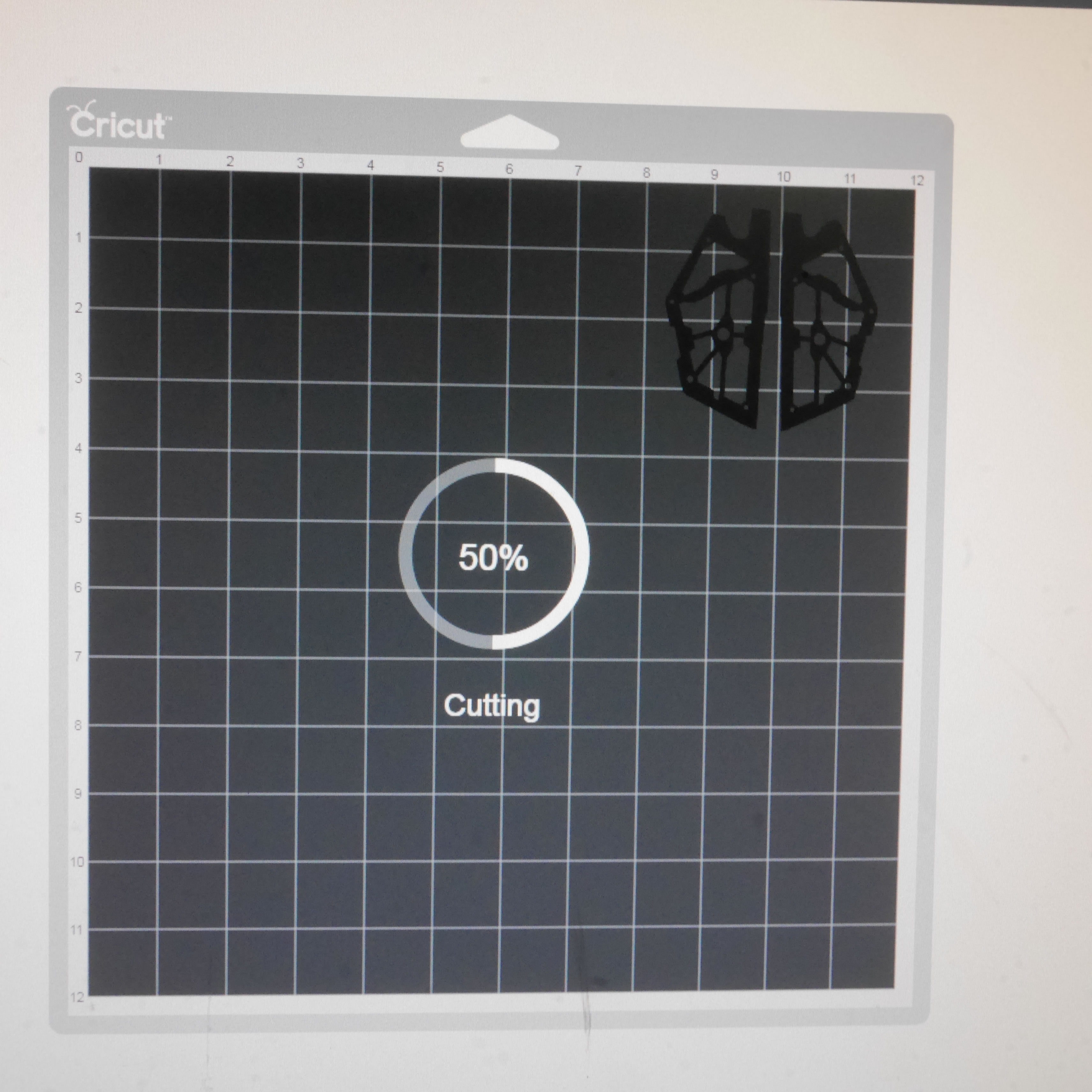
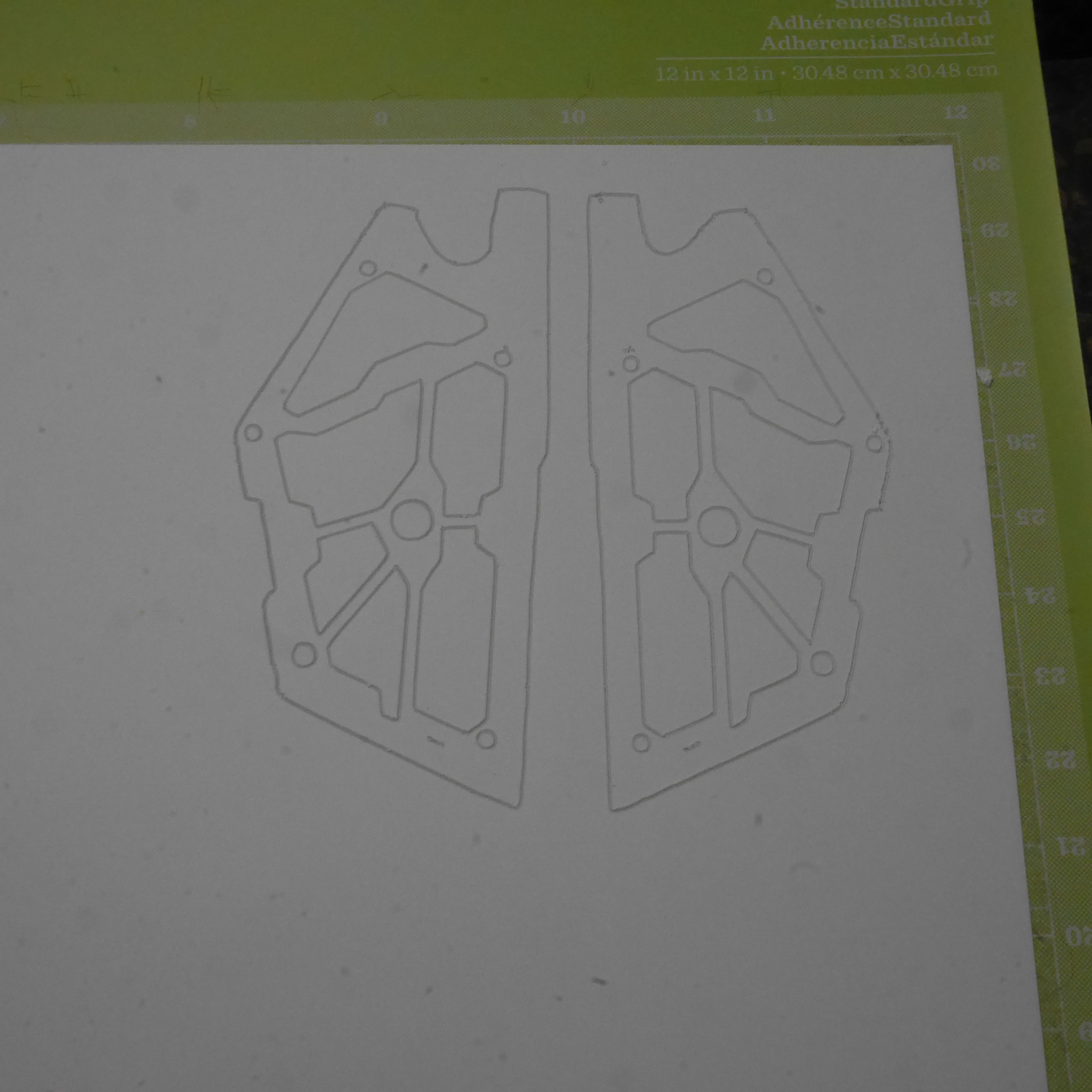
The dimensions are locked in, the design is sent to the cutter. I’m using a cricut air explore 2, the setting is for poster board, and the blade is the deep cut blade. The cutter runs with a .4mm thick sheet of styrene. One pass with the cutter will cut almost all the way through the plastic so that I can pop the plastic out or scribe/knife trace it to remove the excess. But a second pass with the cutter will completely cut through the .4mm. I can probably do this with slightly thicker plastic and get decent cuts just by running the machine on multiple passes. Below is the cutting process.
Once cut, the frame is popped out of the plastic.
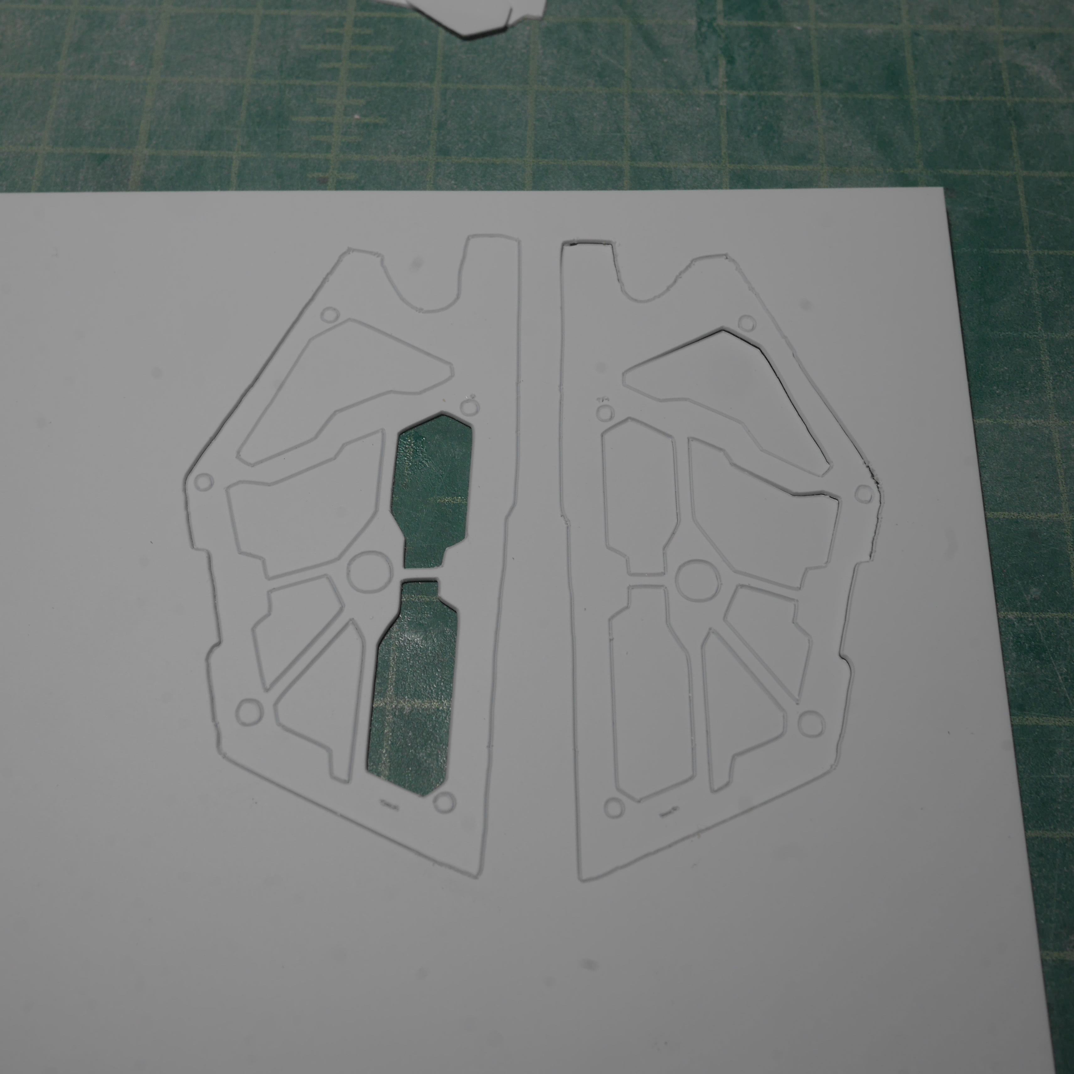
The frame is test fit against the back of the skirt and it is a pretty good fit. Since the back of the skirt was not finished (sanded smooth) I needed to sand it before gluing the frame. Since the back of the skirt is styrene, I just used tamiya extra thin cement to glue the plastic frame onto the skirt. After some small putty fixes along the edges to blend everything together, the skirt is primed and it looks like a solid piece.
While working on the above, I did some continued work on the ammo drum to add in magnets so that the top and bottom frame can hold the drum in place and be removable for transport and ease of painting. The side skirts got some additional finishing after test fits with the front and rear skirts (shown later). The top of the skirt connection piece got some drilled out details and plastic strip details.
Rear skirt work continues with more bondo to build up the edges. There will be lots of test fitting against the skirt to get the correct shape for the meeting points.
The bondoed areas are sanded down and constant test fitting done to shape the edges. Note that the test fitting is done with just the waist piece. This comes into play as this was the incorrect test fit. Even when I had gotten the surface smoothed out and fitting perfectly, this test fit did not account for space with the legs. It also did not account for the spacing and positioning when the front skirts and front belt piece are in place too. An important lesson in planning. This is a 3 dimensional piece, and test fitting against only 1 of the multiple sides can have drastic problems if the other sides are not accounted.
That brings us back to more bondo to rebuild what I had sanded. The legs pushed the side skirts out. The front belt and front skirts slightly change the position of the side skirts along that axis, so I really needed all these pieces in place while I test fit and sanded down the rear skirt. Learning my lesson here, I kept all the parts affecting the side skirts position static while redoing the sanding work on the rear skirt. My brain tends to go 2D when I should be thinking 3D.
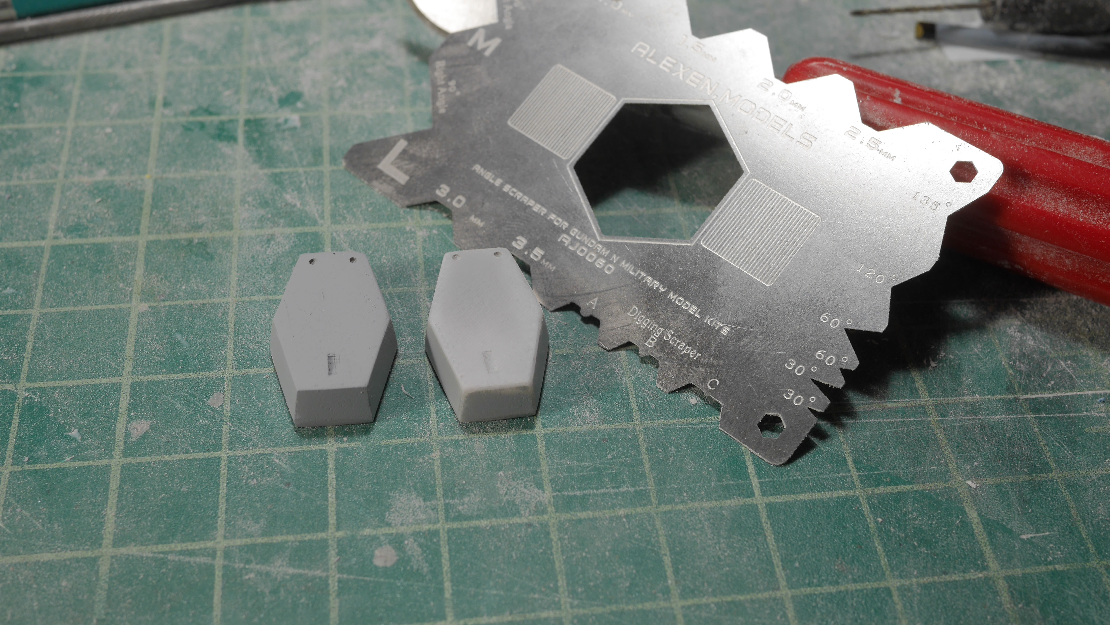
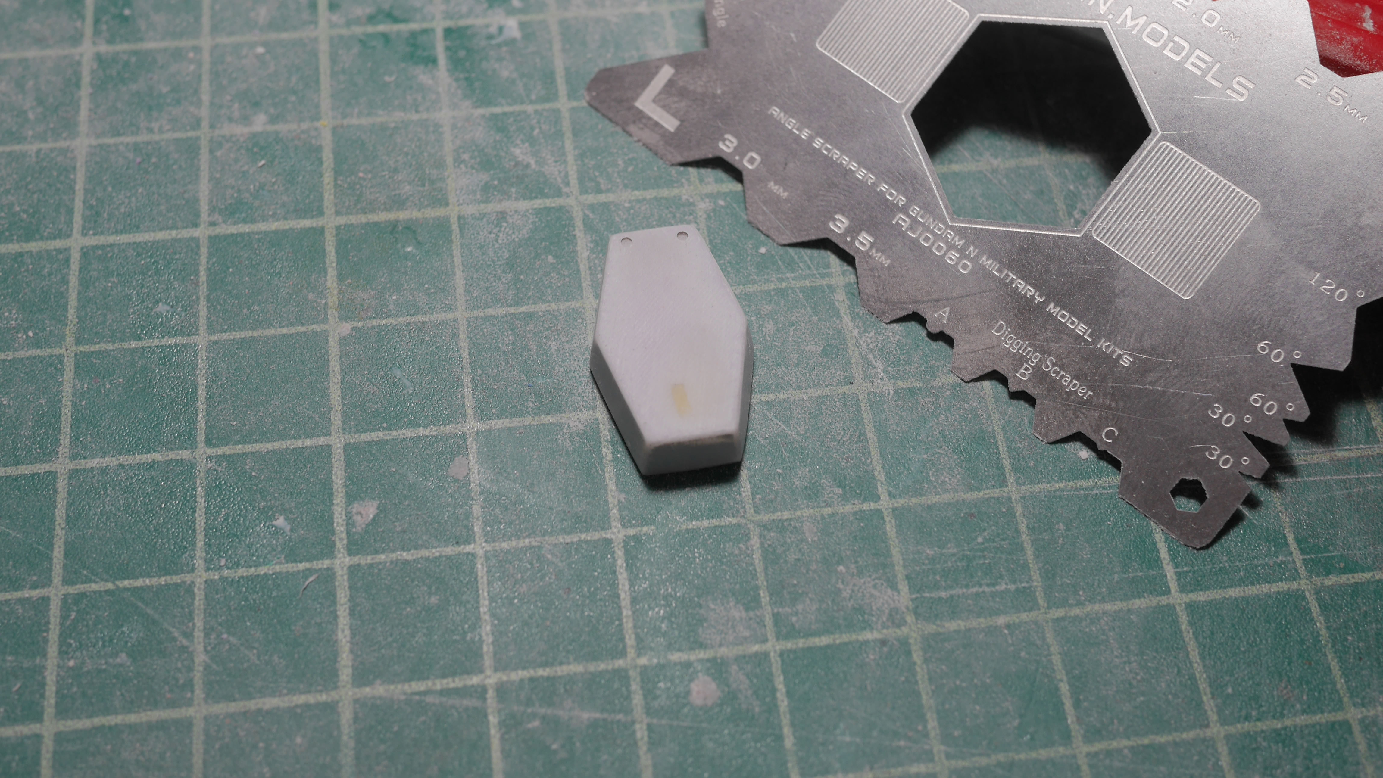
A few years ago, I picked up several tools from Hong Kong and there are still plenty of those tools that I have not used yet. The alexan scraper tool is one such tool. I used the scraper as a beveling tool and beveled the larger missile pod covers. I had also scribed details on the missle covers and when I did this, I eyeballed the measurements. So while it kinda worked for one of the covers, it didn’t for the second. Laziness in these small moments usually comes to bite me in the asshole later.
Light curing putty is applied and I went in with proper measurements to lay out the guide tape for rescribing in that detail bit.
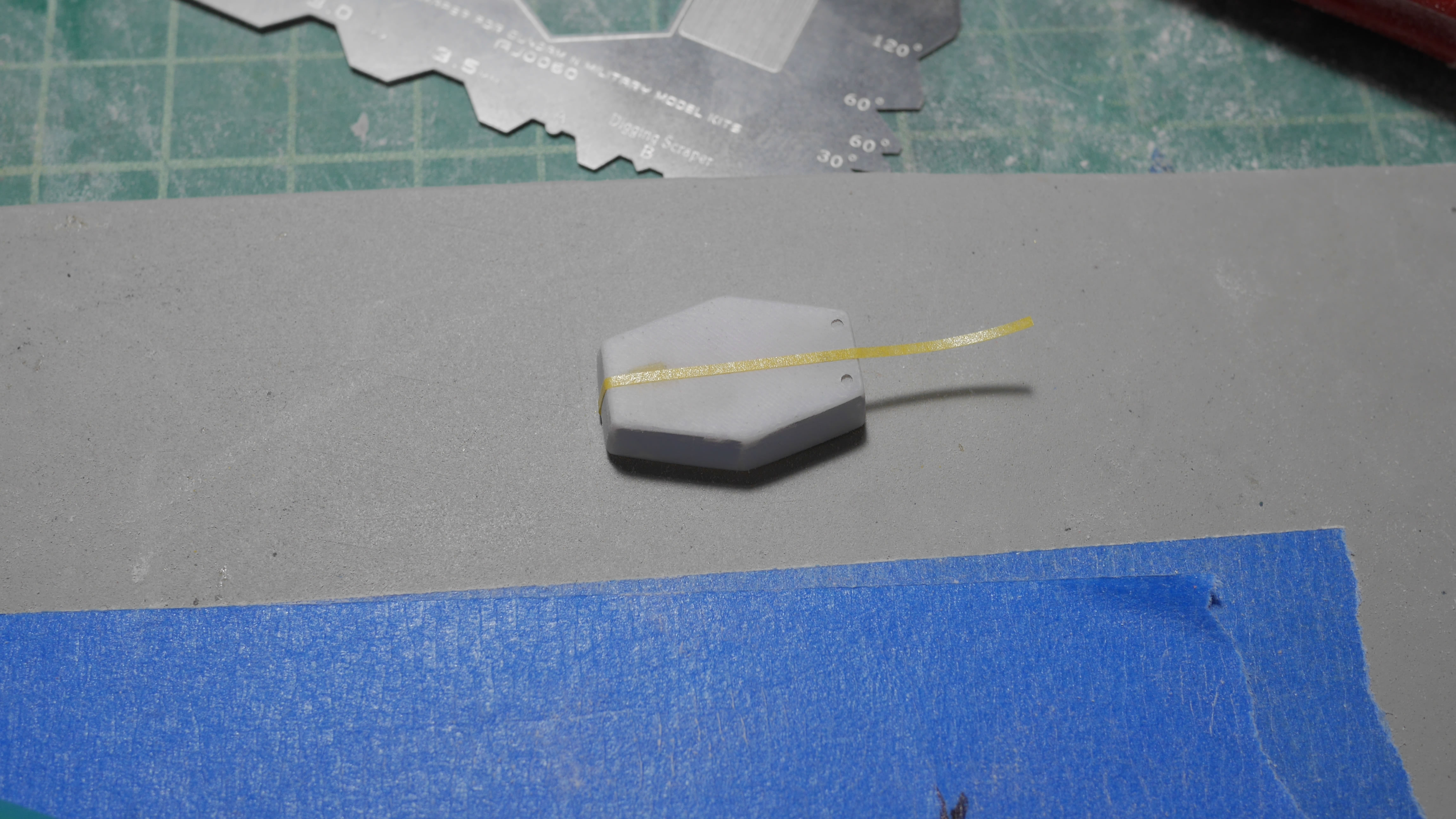
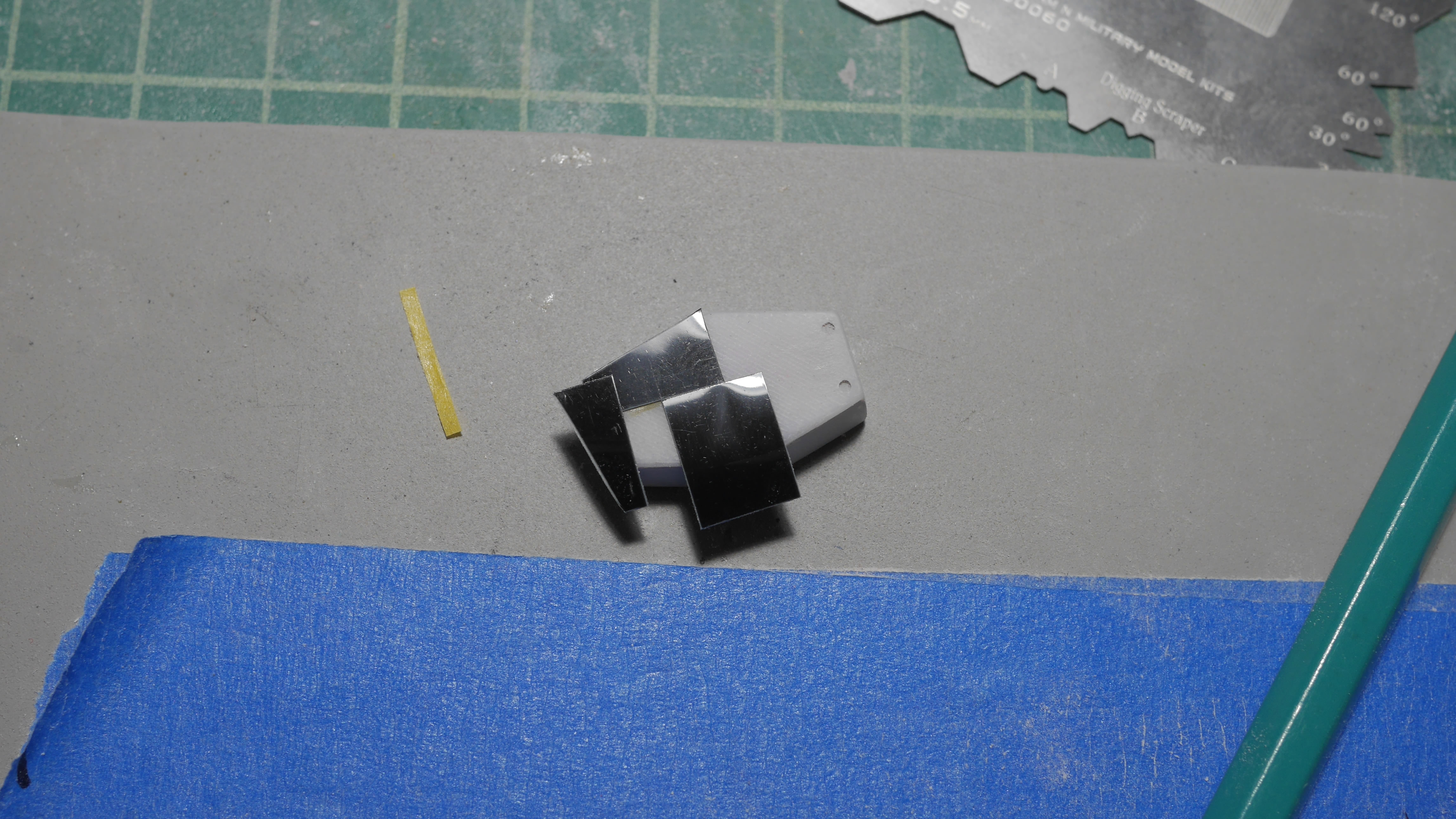
The fix is easier seen after the part is primed. But the first picture you can see where the putty filled in the skewed detail line and the new scribed detail. The lesson here is to just take the damn time to measure correctly. Also of note. Everything is fixable, so never be afraid of making mistakes; because you will make mistakes. Everyone makes mistakes when building.
I joined the Mechanism live broadcast friday night and did some of the above work during the broadcast. So I did a quick dress rehearsal for the sake of the broadcast. This also works well as a before and after for the next stages of detail work – the chest detailing and fixes.
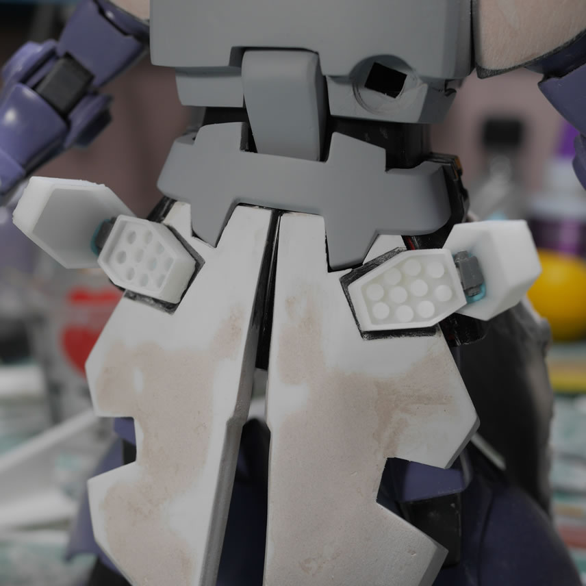
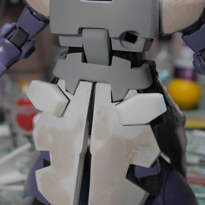
First detail piece I wanted is to scribe a line down the middle of the chest piece. I made the appropriate measurements and laid down the guide tape and scribed the line. The process is pretty simple and just a repeat of what I’ve done in previous scribing sessions. Measure first!
While scribing this detail line and planning out the other details I want to add, I realized that I didn’t like the bevel on the chest. The were not uniform because I had sanded the bevel by hand which has absolutely no precision. The best thing to do is to create a jig for hand sanding that makes things uniform. But since I recently rediscovered that I had a tool for scraping out bevels. Time to use that tool. But first, I need to rebuild the edges of the chest, effectively erasing the bad bevel.
This is where light curing putty comes into play. I work on one side first by applying the putty to the bevel, place the part under direct lighting for a few minutes to fully cure, and sand the surface to recreate my hard edges on one side of the chest. The same is done to the other side. Light curing putty is an amazing tool for quick fixes such as this that does not completely derail the workflow. Once the edges are sanded to the correct edges, the beveling scraper is used to create a uniform and smaller bevel.
The unprimed visual is harder to notice; but easier to see once primed. Below is the before and after comparison both primed. I think the bevel looks better now. The added details later will further accent this. The last picture shows the guide tape in place for more detail scribing.
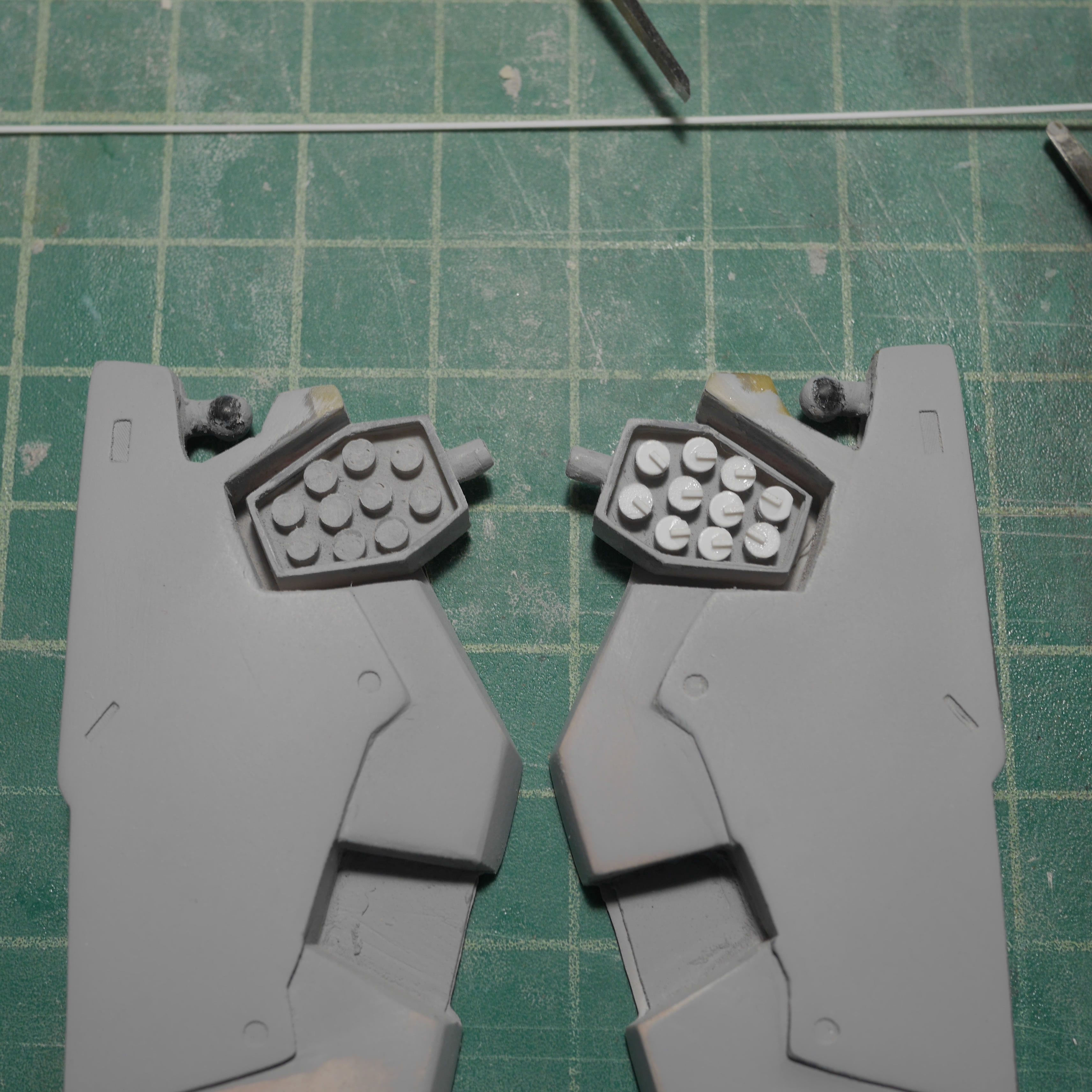
Next up is the work on fixing the missile pod’s missiles. These were originally 3D printed in the FDM, so the finishing isn’t very good and there were holes in the print. My first thought was to apply putty and sand down the filled in holes. But that would take much more work and sanding would be difficult. The easier thing to do is to just cut plastic circles out and glue those cut outs on top of the missiles. I have a punch tool that I can punch out different sizes of circles.
Once the circles are glued to the pods, another detail strip of .5mm x .5mm x 1.5mm is cut and glued to the top of these circles to finish the detailing.
The chest detail work is done and after another priming session, I did a quick mockup to make sure everything still fits and looks correct. I bought the kit out to RoboToyFest that happened Sunday, June 9, 2019, as we organized that judged the RTF mecha contest.
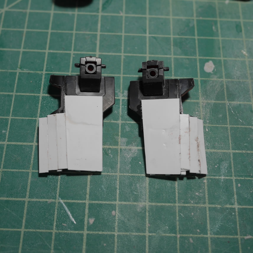
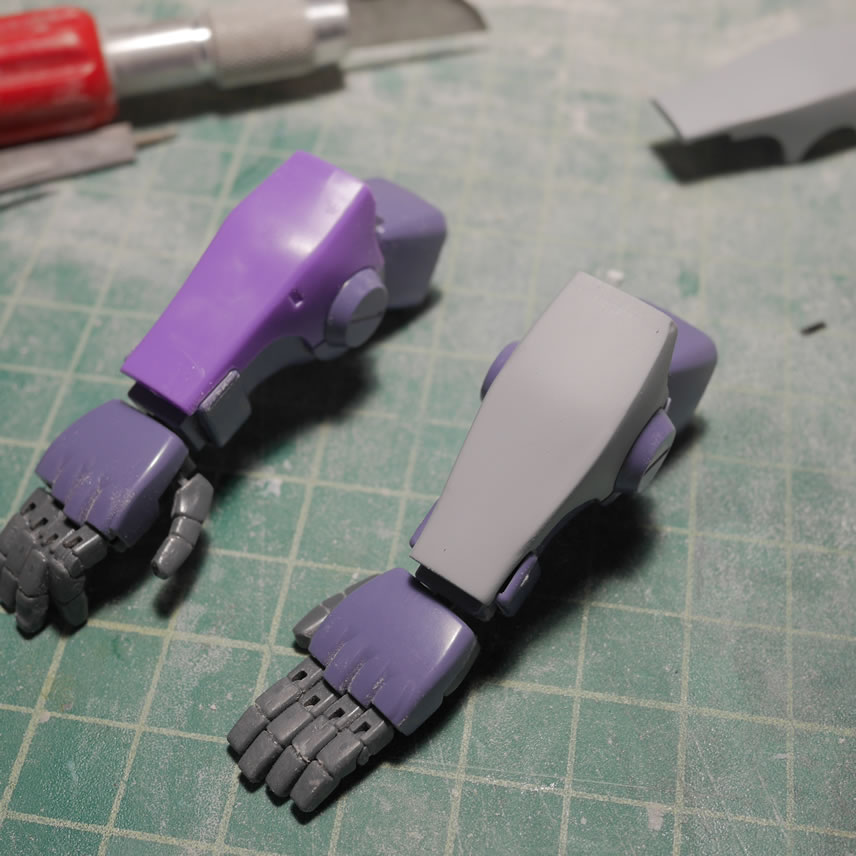
It was a busy weekend so I didn’t get as much work as I wanted. The very last bit of work is the beginnings for the arm modifications. My style of working begins with blocking out the area then sanding and cutting to sculpt. Plastic strips are cut and glued to the arm pieces Saturday night. At the tail end of Sunday night, I started sanding and shaping one of the arms.
So far so good, shorter walls of texts and I have a decent amount of visual work.
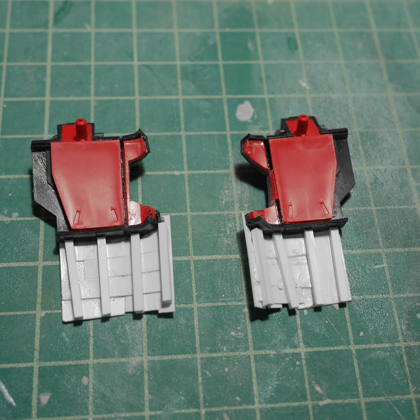
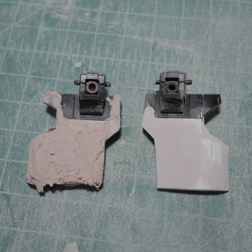
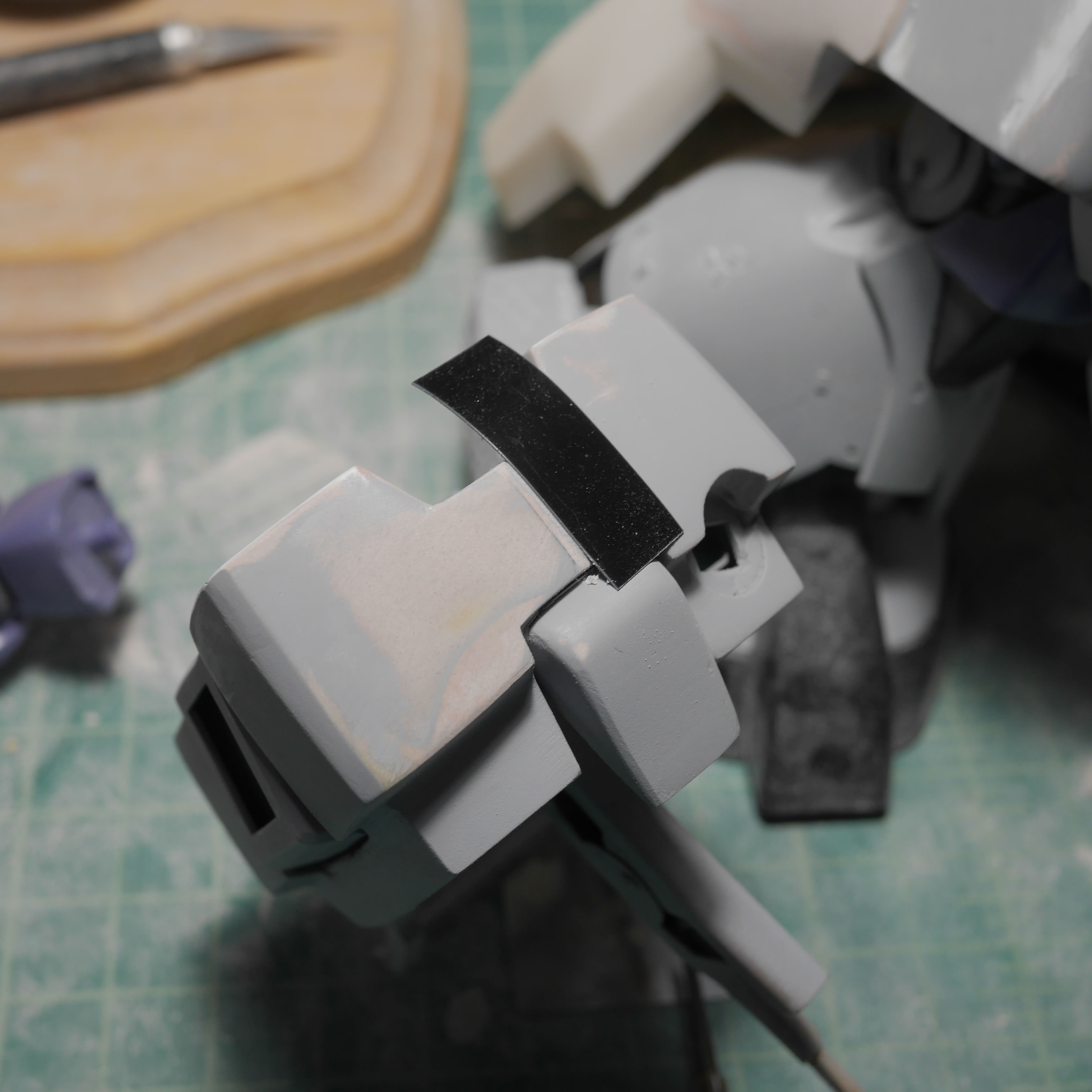
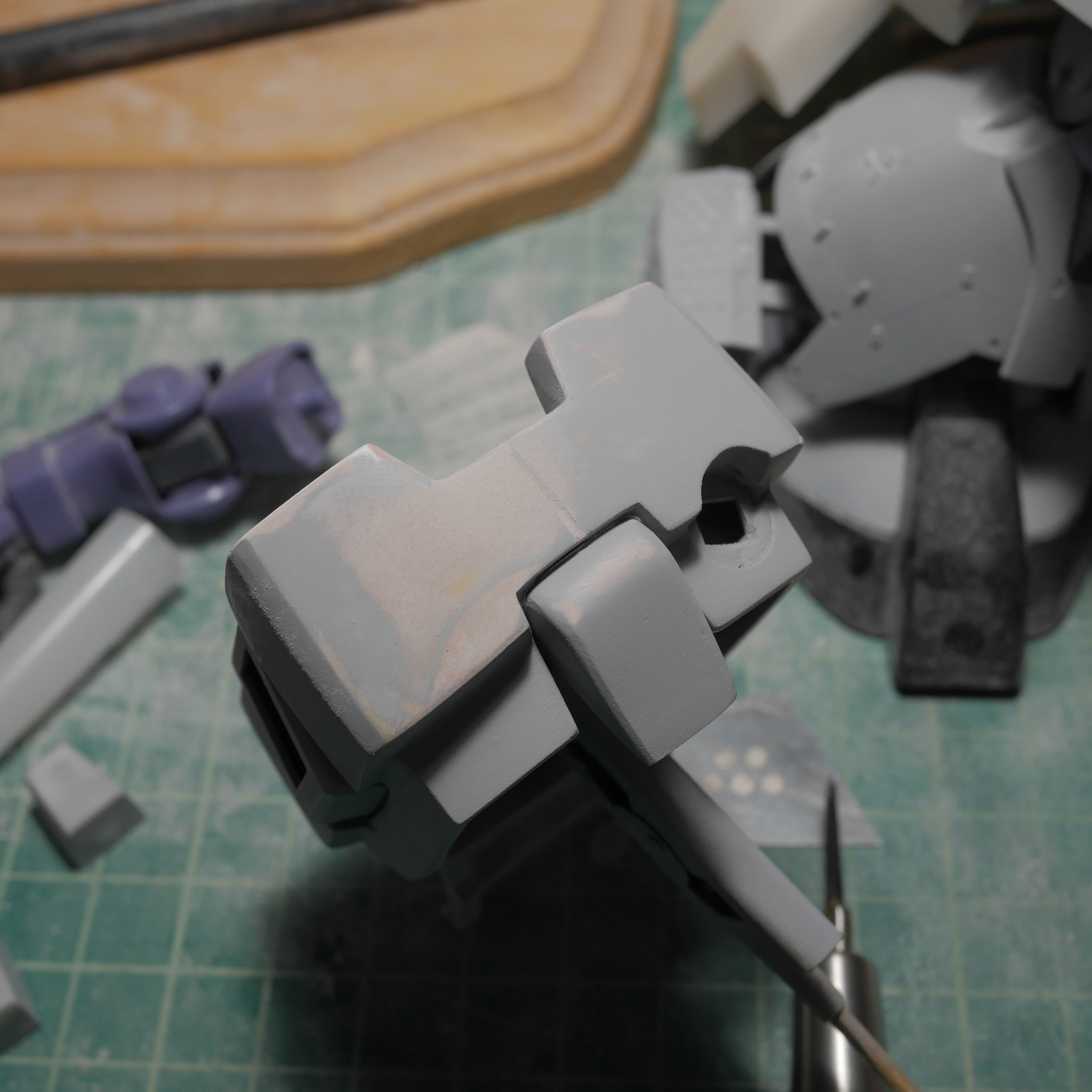
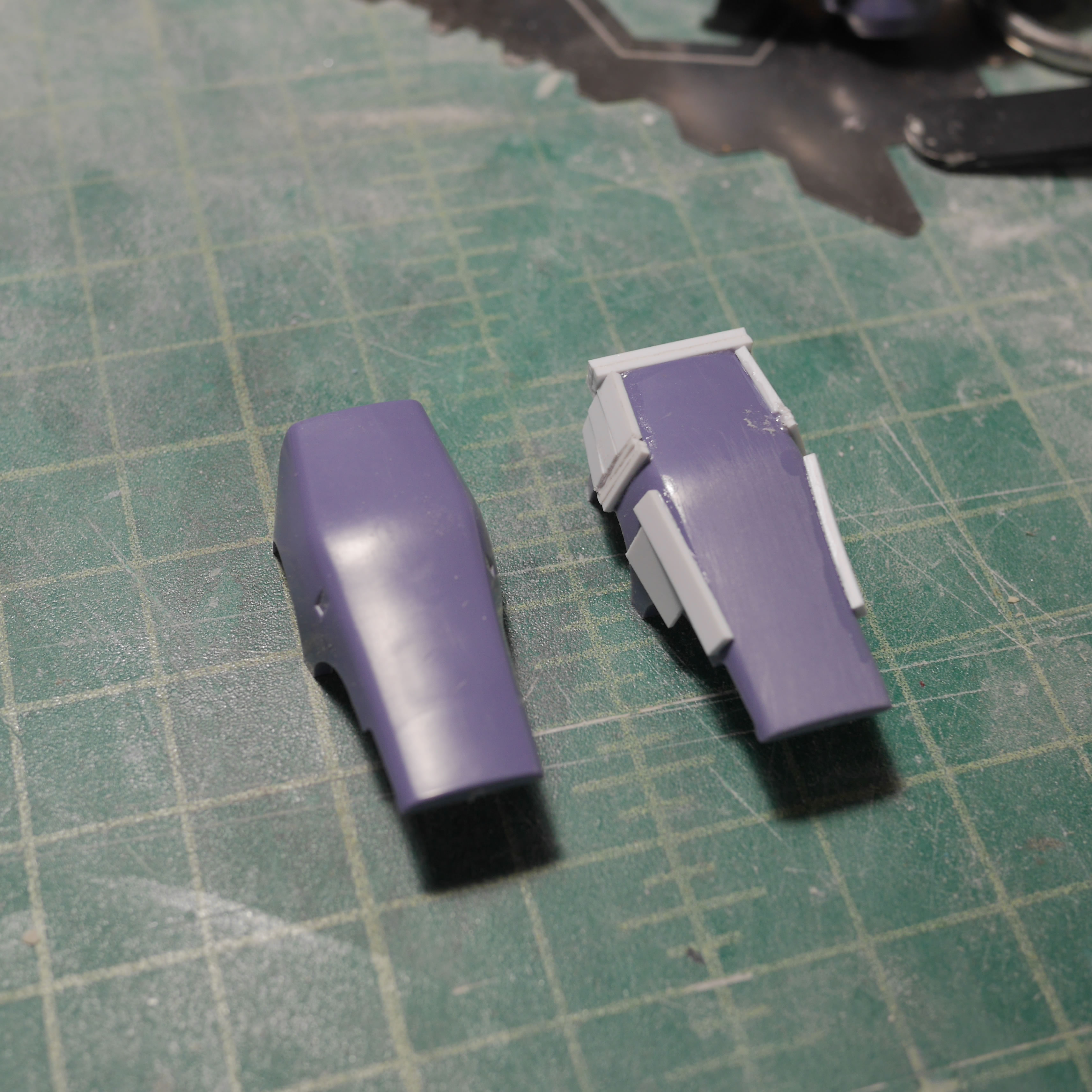
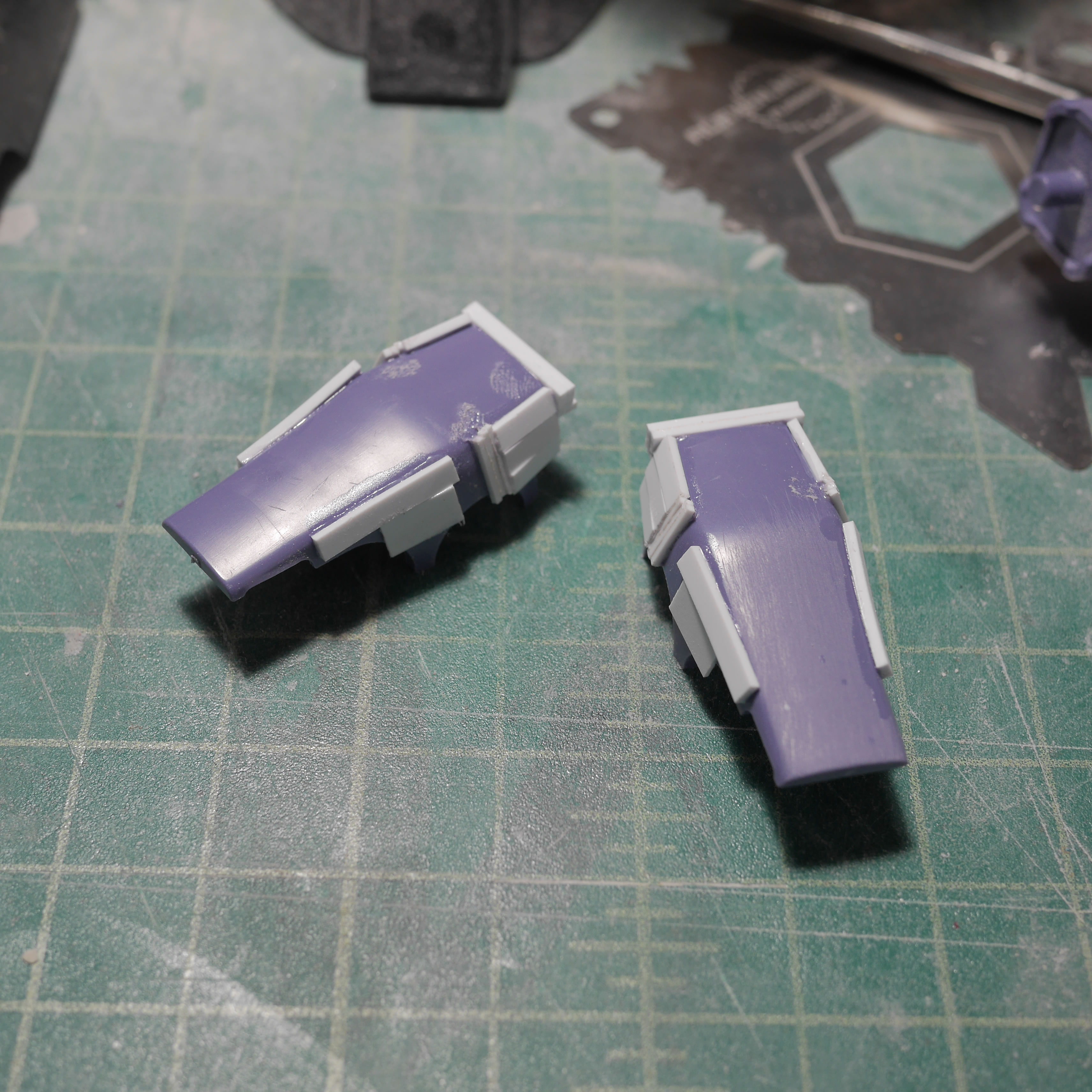
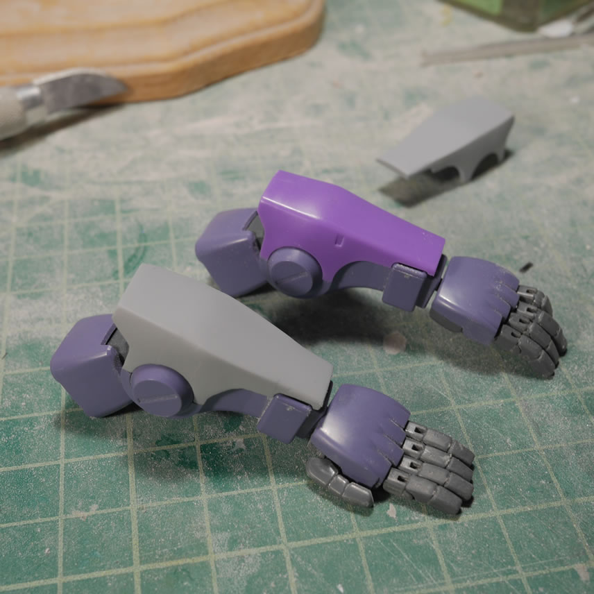
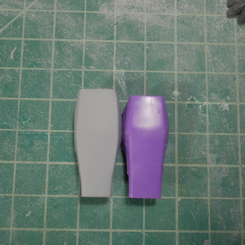
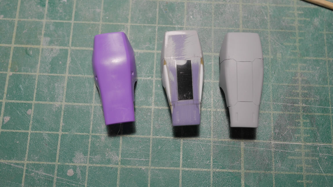
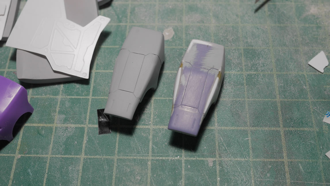
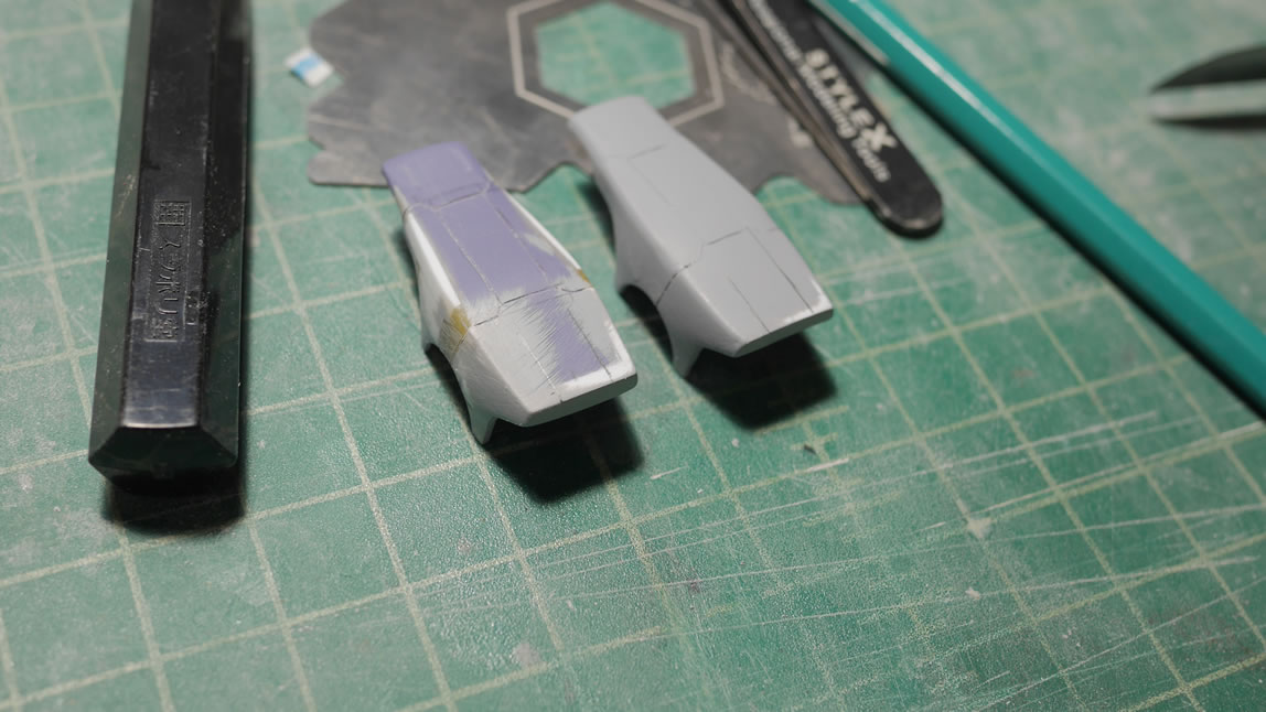
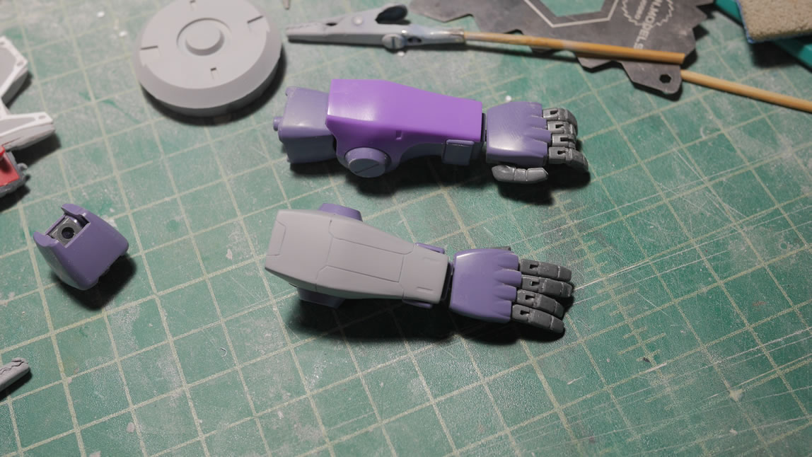
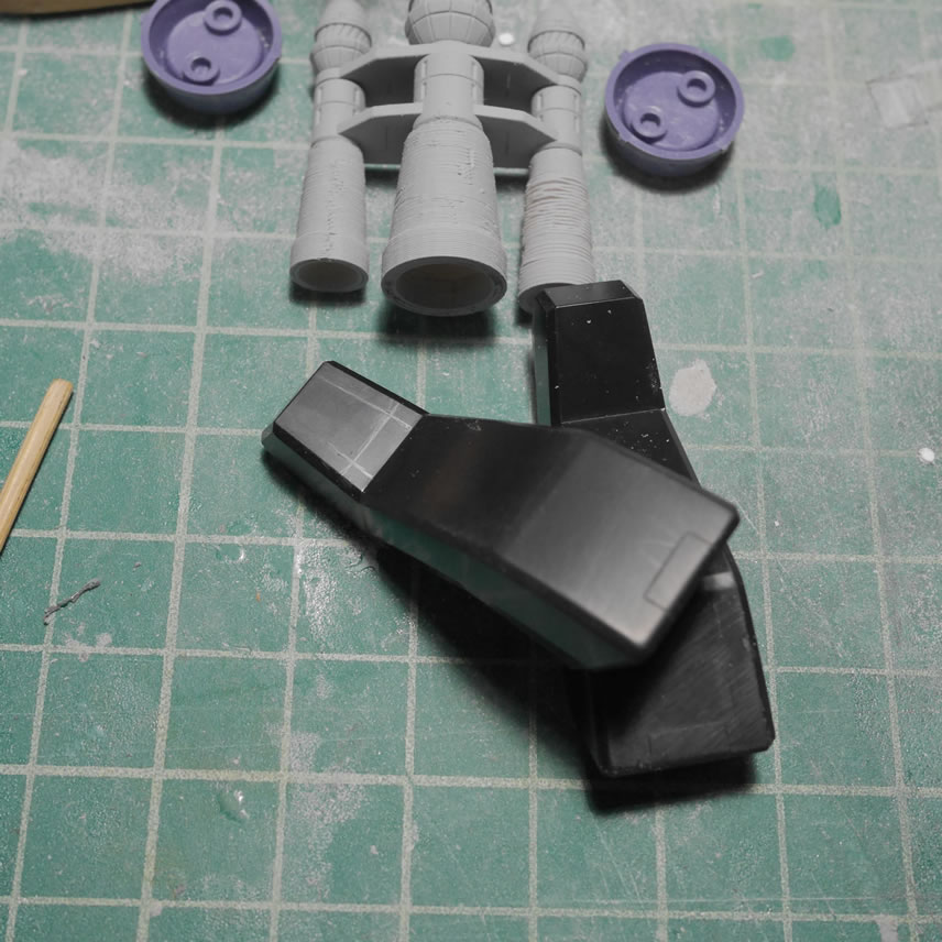
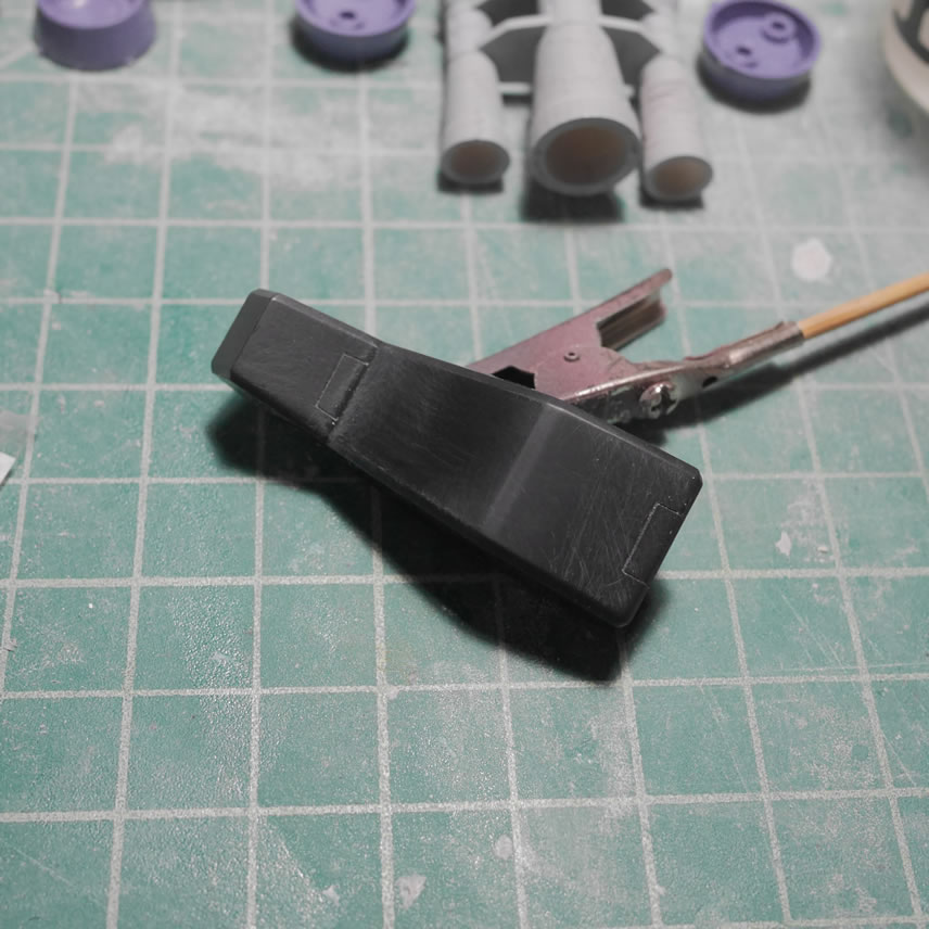
June 17, 2019: Holy crap, holy crap… I’m finally getting into actual paint that isn’t primer! This is a small update, but only because things are slowing down with the build and I’ve been doing more detail work since the big blocking and building. This post starts with the arms. Looking at the reference pictures, the arms are more boxy than the standard Dom, so I started gluing plastic strips to the arms. Once that cured, I added some putty to fill in gaps and sanded and shaped the part. Then a layer of primer to check the modification. The process for beefing up and squaring up the arm piece is pretty straight forward. Styrene for blocking, putty for gaps and filling in missed areas, then sanding the thing to shape it out.
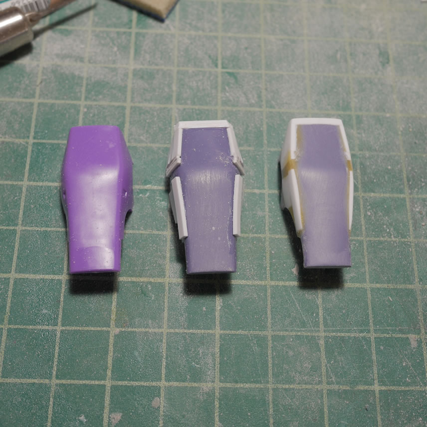
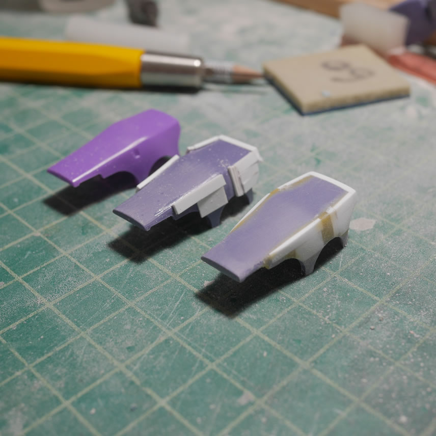
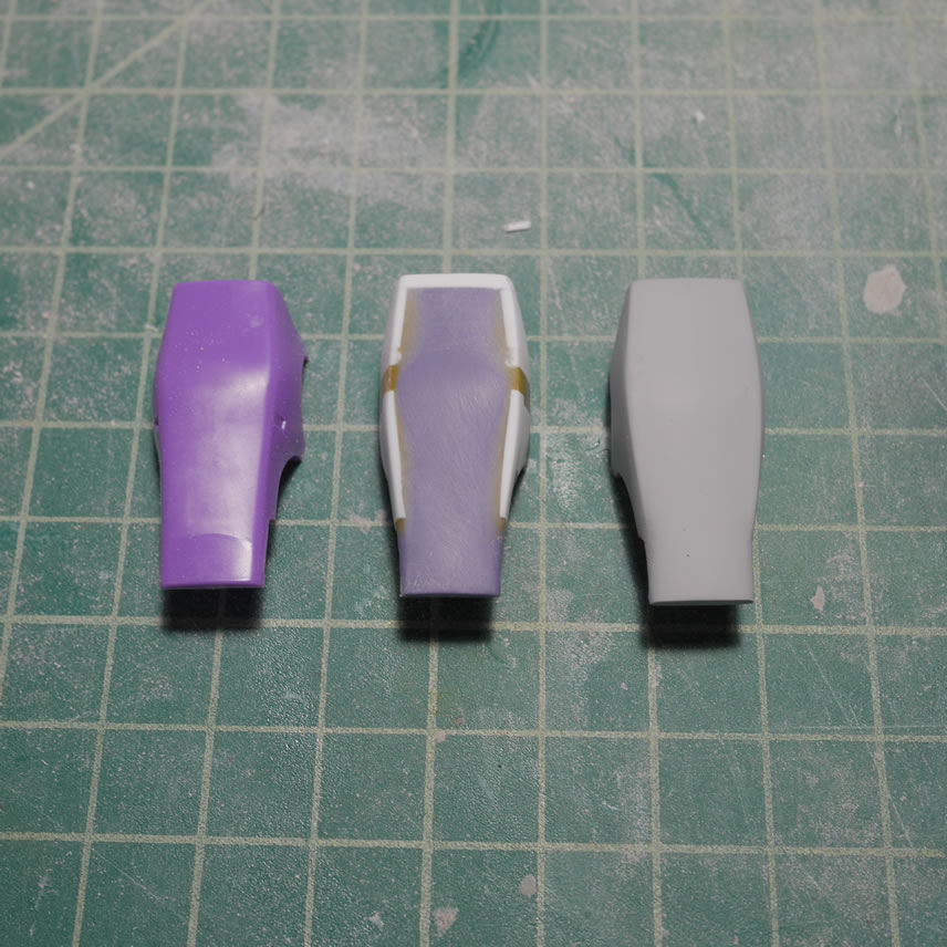
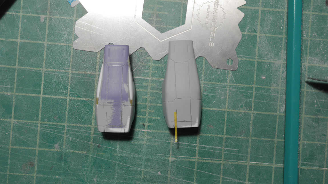
I did a quick test fit with the whole arms for a before and after. The arm piece has been extended slightly and the sides are less round and beefed up a bit. The top of the arm piece is a little flatter now. There is still a high point in middle back of the part but it isn’t as pronounced. The last picture in the set below is the top down to see how the sides and the length are different. It is a very slight mod, but the difference is pretty visual.
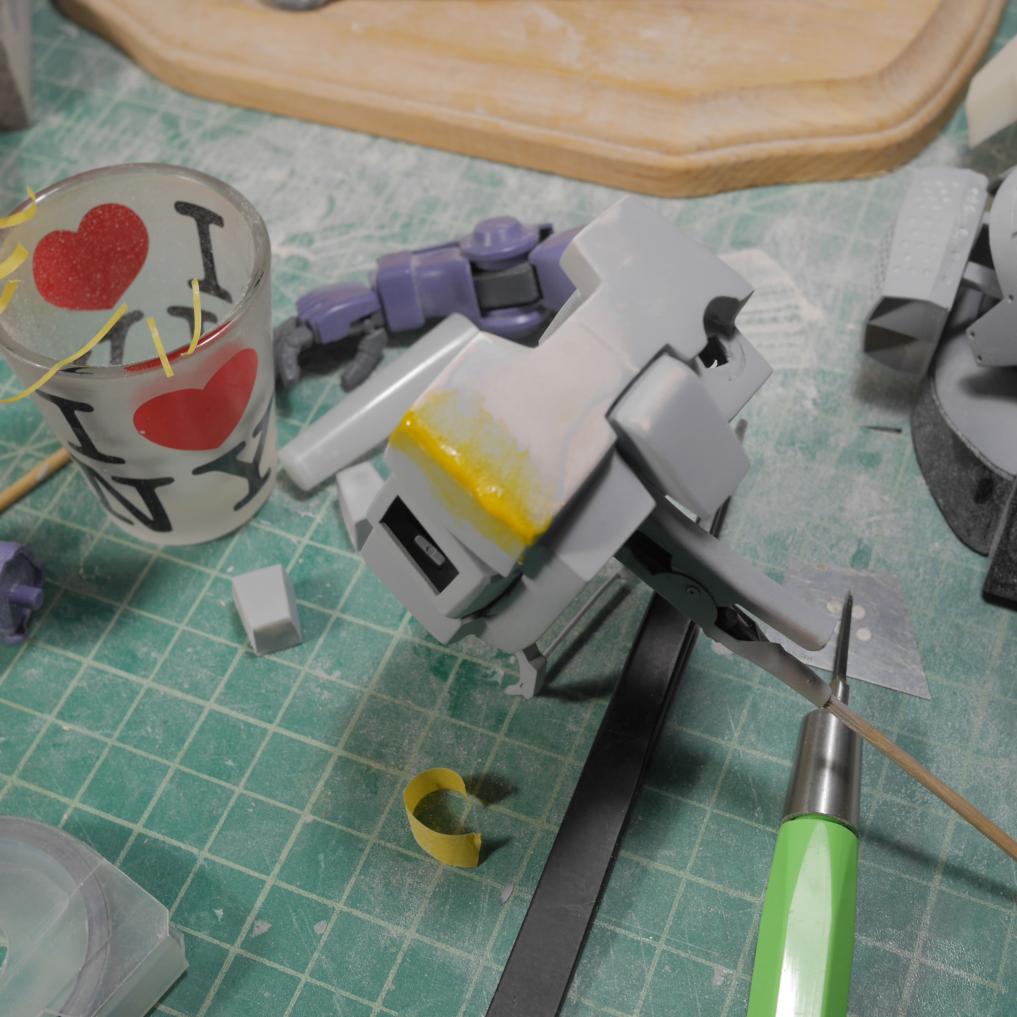
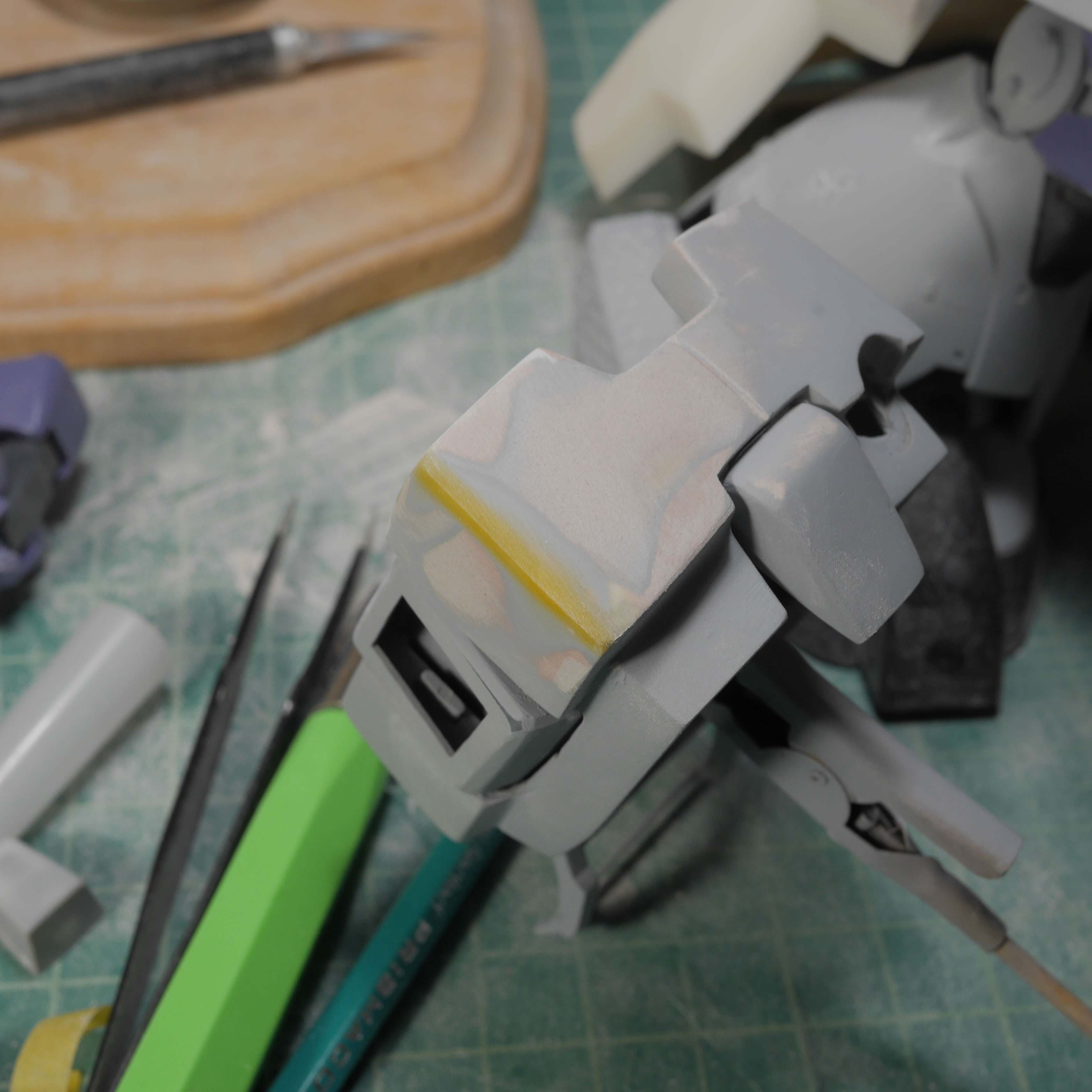
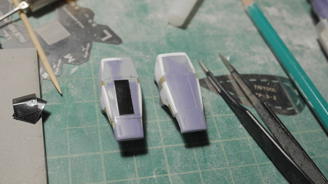
Not pictured are the several cycles of priming and sanding to fine tune the cosmetics. But once that was done, I can get down to drawing out some new detail lines and scribing. The process is pretty simple. I use masking tape of different thicknesses to measure out the area I want the details. The masking tape acts as a guide for some pencil lines. Once the lines are drawn, the masking tape is removed and dymo tape is employed as the guide for the BMC chisels. I’m using the .2mm chisel. The scribing process is just a light drag of the chisel across the plastic along the edges of the tape. I tend to count the number of passes so that when I do the other side, I get a similar depth. Each pass of the chisel will scrape a thin layer of plastic. Do not press down and try to gouge out the line in one pass. This requires patience and your results will be much better if done slowly. Once the scribing is complete, some light sanding to remove any excess burrs or by products of the scribing process and then a layer of primer to check on mistakes or get surprised that it came out well.
While doing the above, I live streamed the process for about 2.5 hours. You can check out the video here:
The scribing is done in sections. I did the front area first. Then moved onto the middle area. then on to the back. For me, it is easier to do this so that when I make a mistake, I can easily fix it first, then move on to the next area. I also applied a bevel to the edges with the beveling tool.
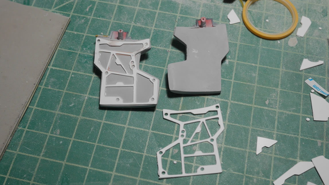
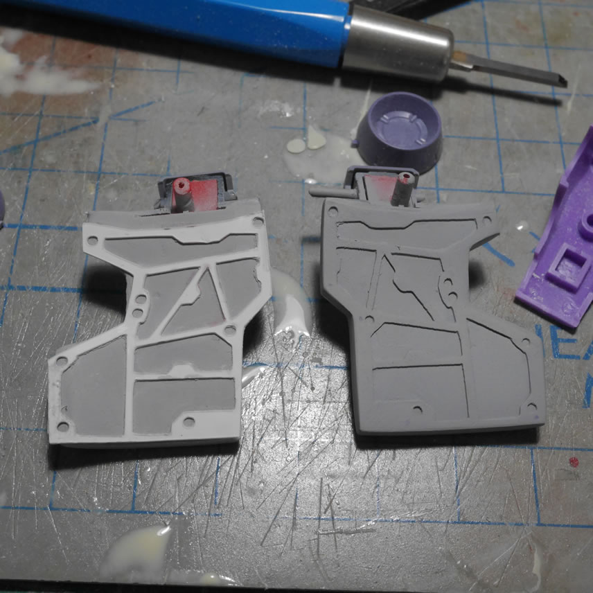
Moving back to the side skirts; I designed and cut out internal frames for them. This is another piece of detail that will never be seen unless upskirting the Dom. I didn’t want to leave the area completely bare, so this was a quick cut, glue, putty, sand, and prime session. With light curing putty, the process was very quickly done. Here’s a comparison between the glued frame and the puttied/primed frame. Note that since I know that this is a throw away detail that is difficult to see; I didn’t spent a great deal of time making it look good. I wanted something there, but I didn’t want to spend an obsessive amount of time making it look good at a close distance. Since it will be hard to see at a close distance. This is cutting corners, but I also want this thing done!
Back to the arms (upper arm piece) for more detail scribing here and there. I got a macro extension tube for my camera and tested it out with the upper arm piece. This part was scribed and sanded down. The plastic dust in the scribed lines work to show the lines before priming. I have an old toothbrush on my work desk to clean parts like this before getting them ready for primer.
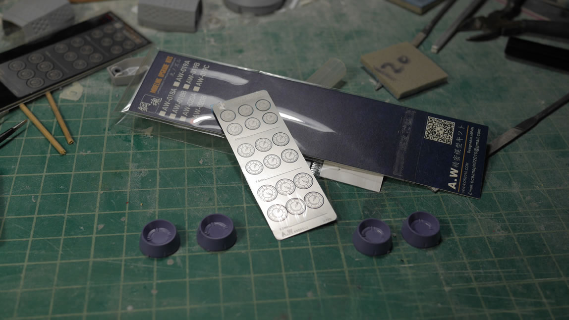
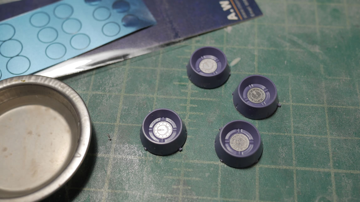
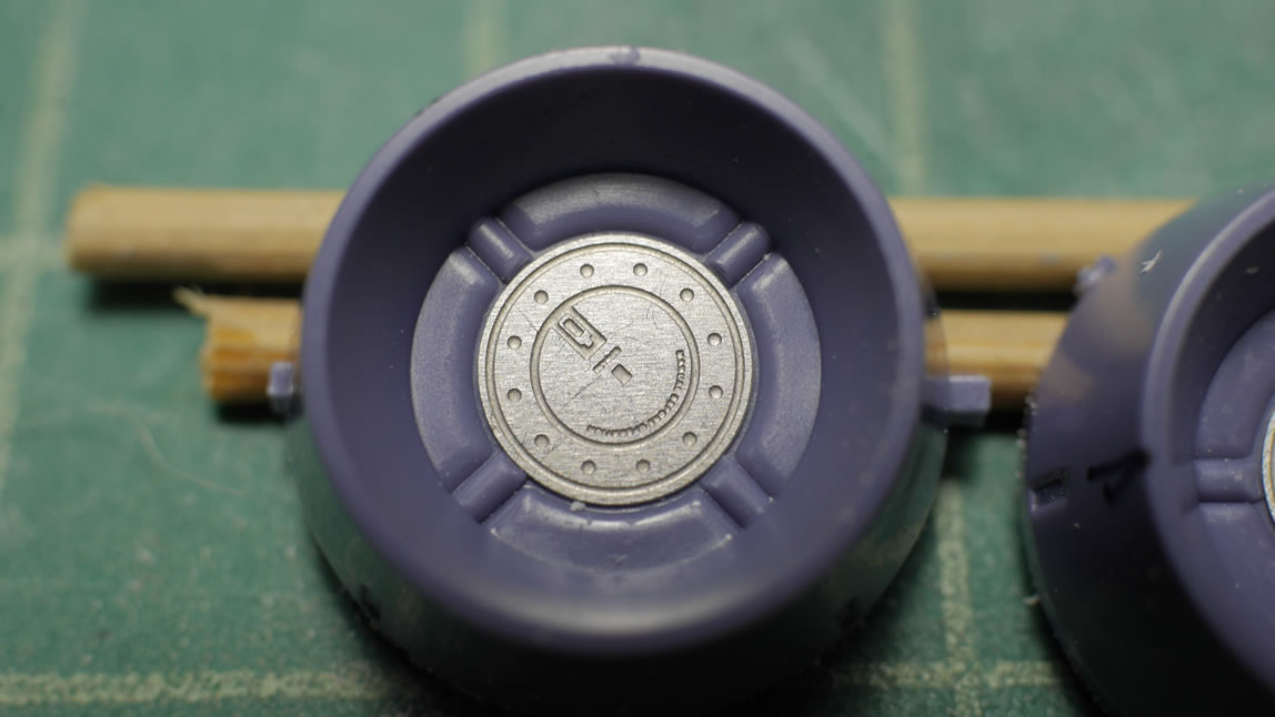
Continuing with the addition of details that will rarely see the light of day, the feet internals looked like a great candidate for such details. Left to right, I added a metal minus mold detail; a koto plastic detail round, and the tiny detail in the last round is a photo etch piece. I picked up the photo etch part from NewTypeHQ There are a bunch of these to pick from. They are amazingly designed as the detail bits are sandwiched between two sheets of tape. They’re completely precut so for those that have used photoetch in the past, there’s no need to clean up after cutting them from runners.
The koto plastic bit was glued into position with regular tamiya extra thin cement. The metal part and this small photo etch detail is glued with regular elmer’s white glue. CA glue (super glue) has a tendency to frost or attack any oils that may be on the parts. And CA glue cures way to fast for positioning the detail bit. White glue is a slow cure and I can position the part correctly then let it set up for a few minutes. Once it has started setting up, I can take a damp q-tip or even a paint brush with some water can clean up any excess glue. The part is left to sit overnight and it is glued very securely. A priming session ties everything together. The photo etch detail adds a great deal of 3 dimensional detail to the part. Here is a before and after comparison as well as the primed part.
Next up, I debated on how to detail the belt piece of the side skirts – something 3 dimensional or scribing. The reference photos show a little detail here other than just the plain belt; so time to get working on that. Similar to scribing, I measured out the area with masking tape and pencil lined the area I wanted to detail. I laid down some madworks carving tape as the guides. From here on out; madworks carving tape replaces the dymo tape. They are just so much better than using the dymo tape in that they’re clear and semi reusable over the one time use solid colored label tape.
I cut in a channel into the part and glued in some styrene strips. The detail is just built up styrene strips. Once cured, I did some sanding work to finalize the shape and add some bevels and then primed the part. I think this looks better than the plain undetailed surface. I wanted something more than just scribing, so plastic plates help give some depth to the details.
More scribing with the madworks tape and the BMC .2mm chisel for the foot piece. Again, masking tape for guildes and drawing the lines, then the guide tape and chisel to scrape out the detail lines. I don’t want to go overboard with scribed lines, but a little here and there adds enough detail without looking too busy. Personal tastes.
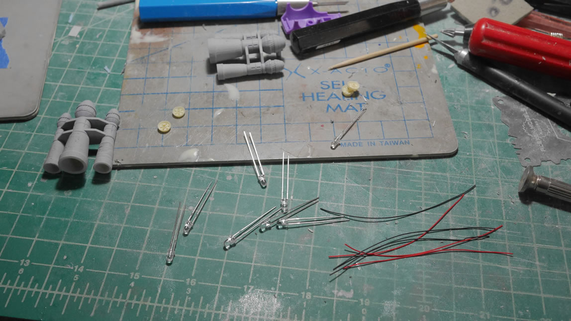
I’m starting to work on the electronics. The thrusters will get some LED lighting, so here are the beginnings for those detail areas. LEDs laid out, wires ready for stripping and wrapping, and the test fitting with the thruster pieces.
Another photo etch detail session for the feet. Paint on some white glue, position the photo etch detail, and done.
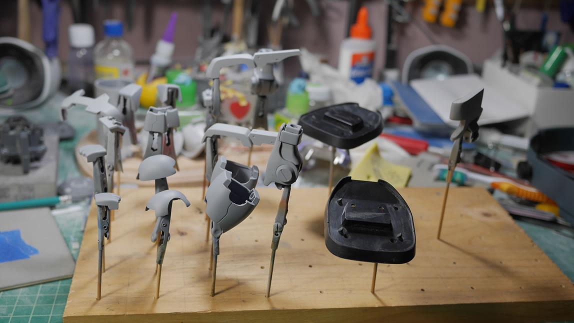
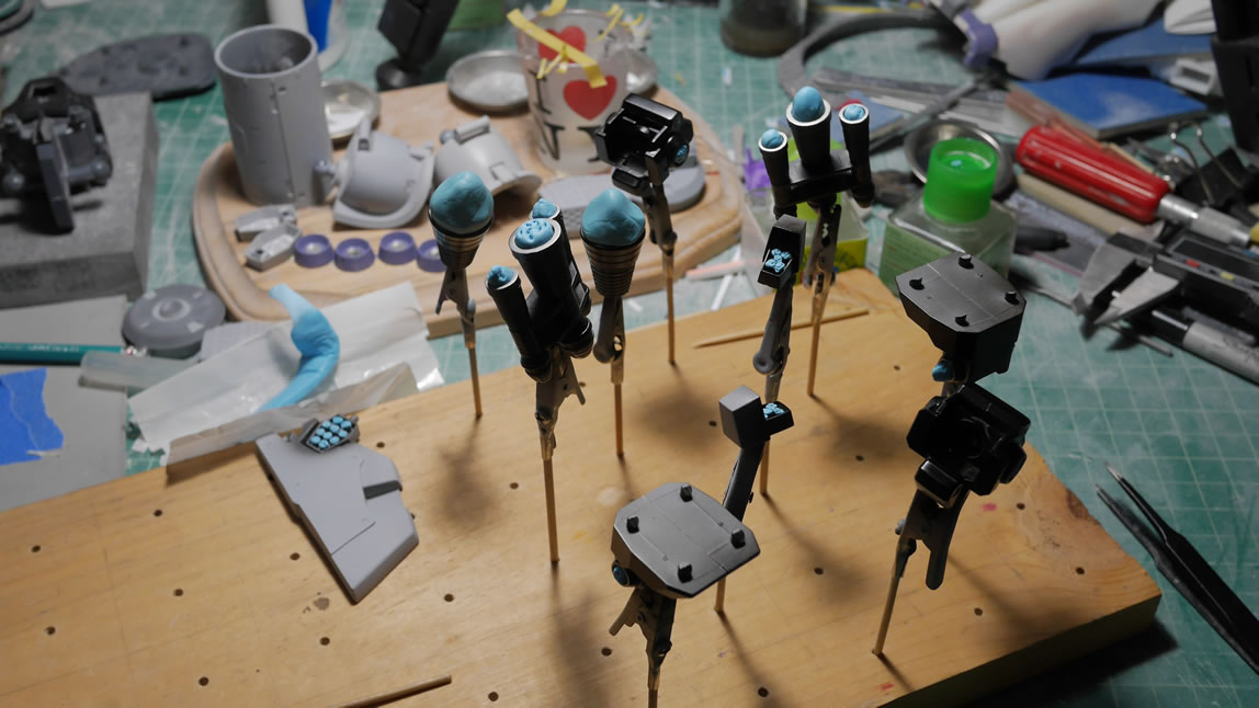
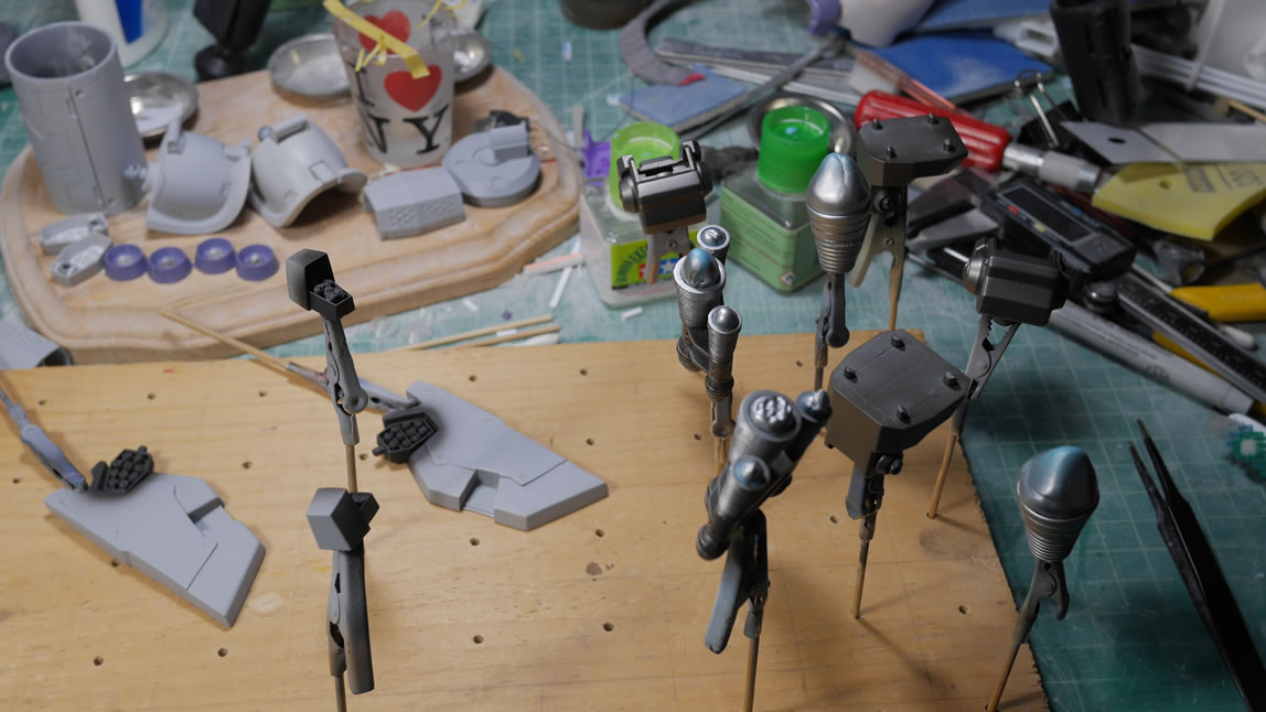
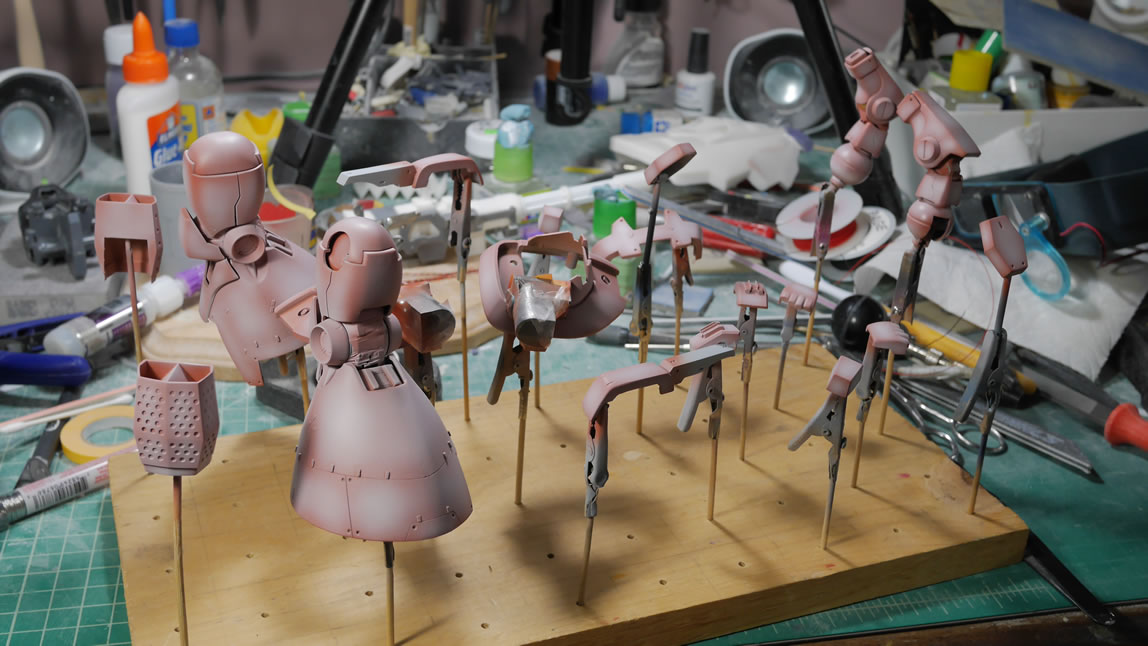
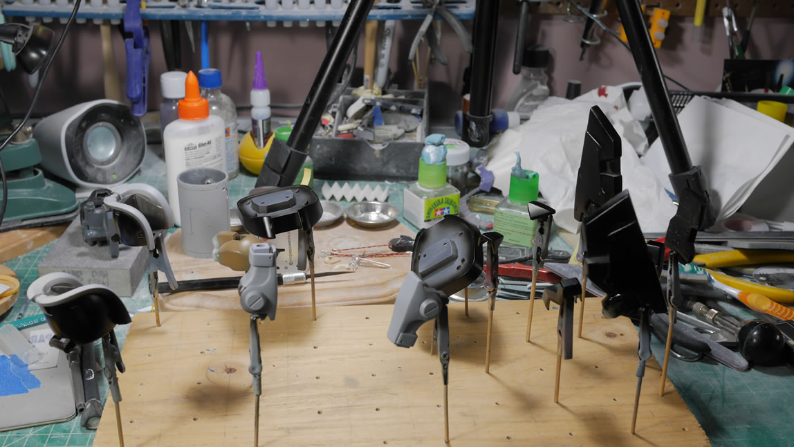
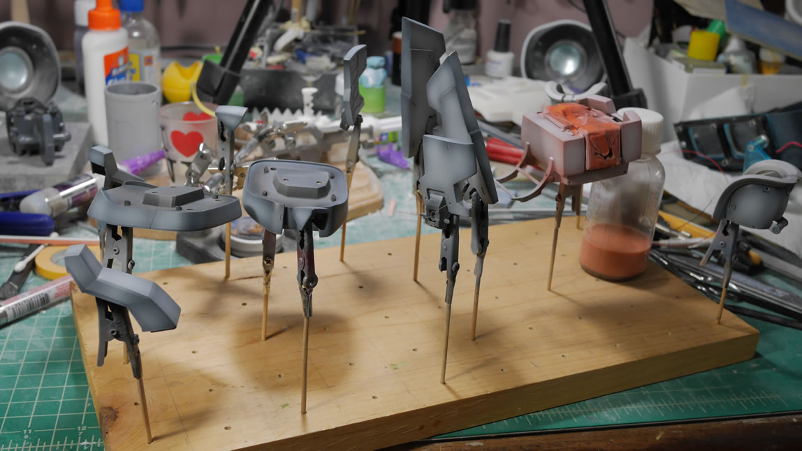
The amount of parts left for detail and clean up work is winding down to a handful. This means the rest of the parts are all skewered and headed for various stages of paint that isn’t just primer.
And here we go. Finally some paint. Black base coats for the metallics and some metallic sprays, and another set just primed and waiting for the first base layer of paint.
The next update should be interesting once I start getting more paint down.
June 24, 2019: The week 4 update is here. And so much to go over for a short post. I’ve gone full blown painting now, but there are still some bits and pieces that need clean up and build work. Namely the rear skirt, ammo drum, ammo belt, and gatling gun. But as of this post, everything is almost done with principal painting. But let’s rewind to earlier this week and since the last update. I was still doing minor detail work. The last update introduced some photoetch addon details. Continuing with that, I added some of these detail bits to the knee joint circular covers. I did have to make a slight modification to the part so that the detail bit would sit flush. There are four plastic details that extend slightly towards the center of the round and those needed to be chiseled away. I did a video while I was working on these but I haven’t had the time to edit and upload it. I’m pushing pretty hard on the kit so I’ll probably get that video up once I’m done with the project.
The bottom of the feet as well as the sides of the ammo drum get some of the photoetch details glued into place with your everyday, child eating, elmer’s glue. Once the glue sets, I’ll prime and paint these parts.
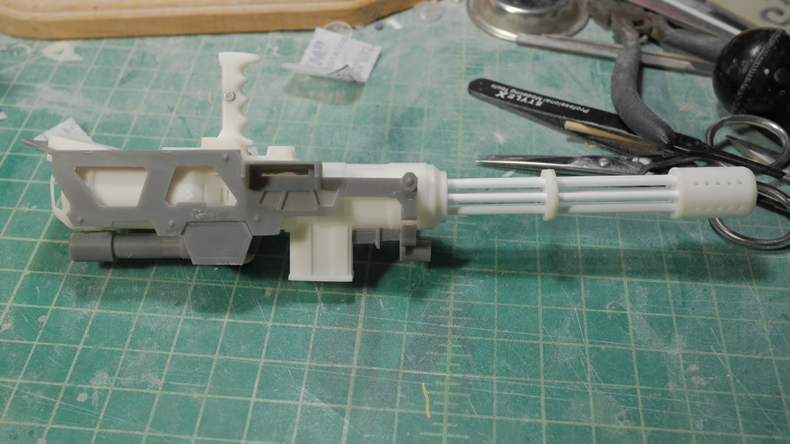
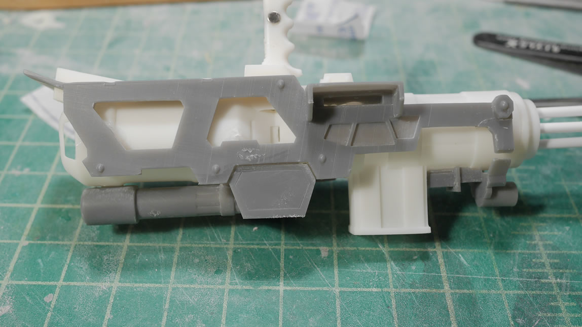
While things are being painted and drying, I return to the gatling gun and get to cleaning it up and just gluing the parts together. The frame is glued to the main gun body and the lower sections of the frame are also glued in and the front bottom detail piece. The alignment of the part isn’t the greatest so I needed to glue in some plastic styrene for some of the gaps in the front of the frame piece where it attaches to the bottom detail bit. Next up for the gun is the sanding work.
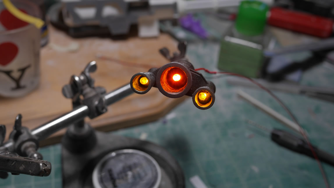
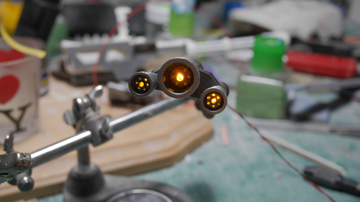
Actual paint is sprayed now. I typically paint the insides or underbellies first, then the outside. So here are some internals getting black based coated then painted with some metallics. I painted up the thrusters then added in some LEDs. Typically, I stop here and move on to the next part. But having the LED just inside the thruster bell felt like just shoving a lightbulb inside. So for something different, I casted some thruster details and glued them into place after painting and with the LEDs lit up, the light is more subdued and I get a more interesting light effect coming through the details. It is a slight change from my usual LED thruster work.
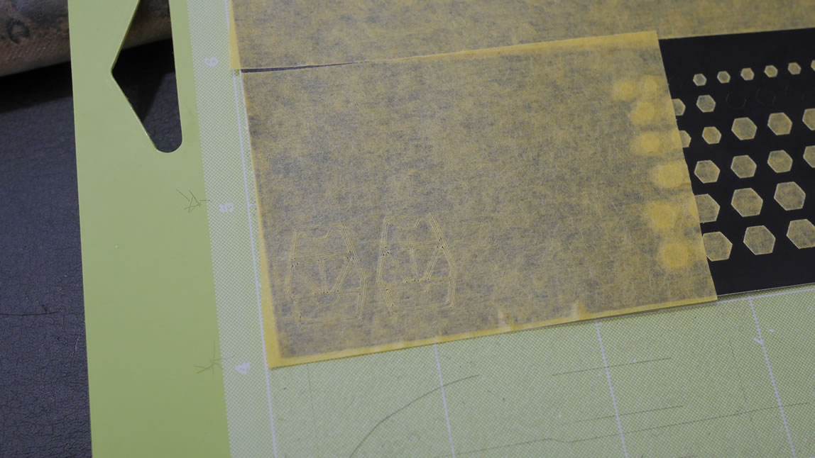
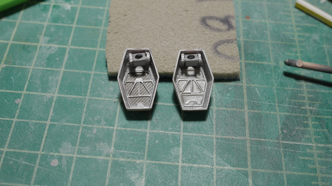
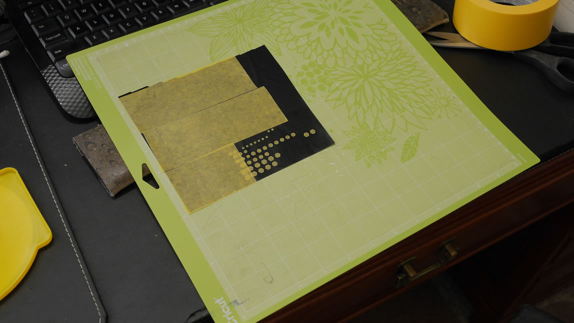
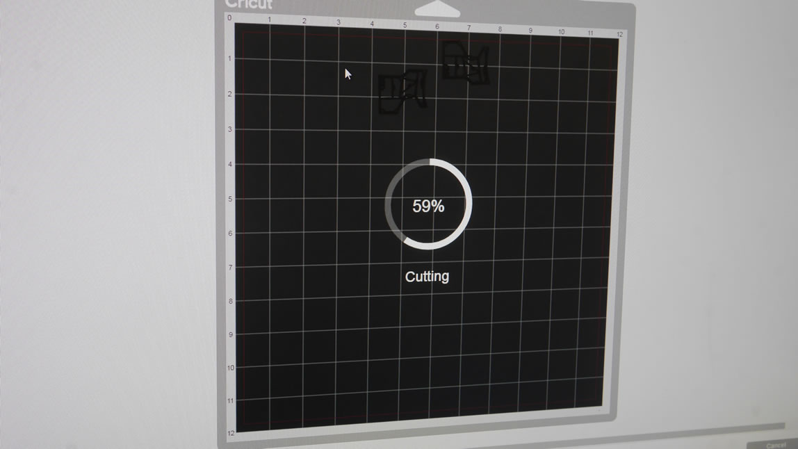
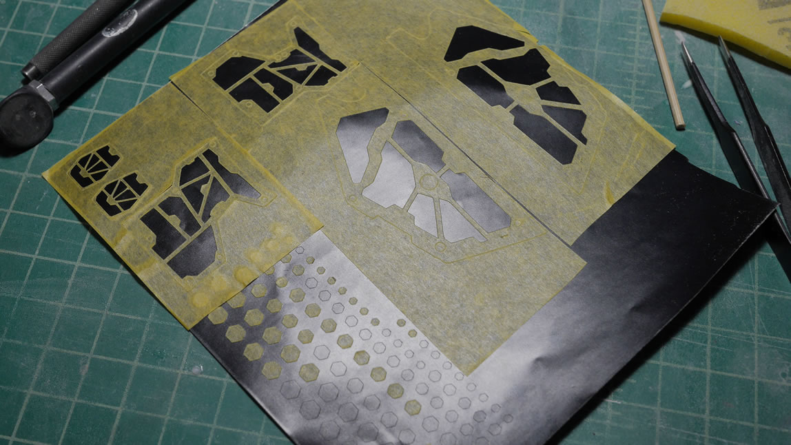
I wanted to add a slight bit of detail inside the missile pods so time to test out the precision of the cricut. I drew out a frame piece and had it cut with the cricut, it worked amazingly. The fit was perfect and since I had the frame piece already designed and measured, I just needed to use the same design with some masking tape attached to a sheet of vinyl sticker and run the machine again with different material settings. The backing on the cricut cutting board is sticky, so sticking masking tape to a sticky surface isn’t the best thing to do. The vinyl tape works perfectly for easy removal of the masking tape after the cut. So with the frame design run through the cricut and instead of cutting plastic, I cut the masking tape, I have a perfect masking templates for the part. The internals were painted with alclad magnesium, masked off, then painted with alclad dark aluminum, and done. It is a VERY small bit of detail and only visible when the bays are open so I’m not too worried about cleaning up the rough edges.
Back to the cricut, more masks are made for the side and front skirts.
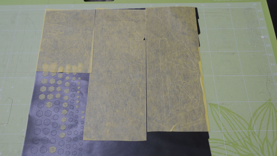
Just cut and apply the mask then paint. That’s really all she wrote on the subject.
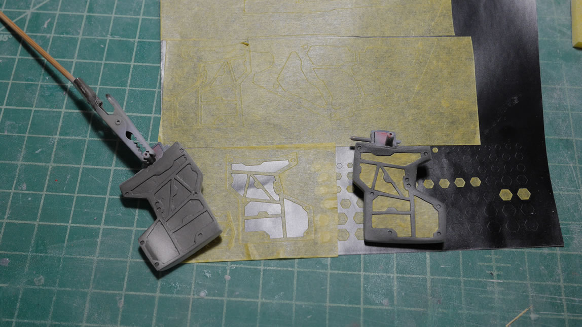
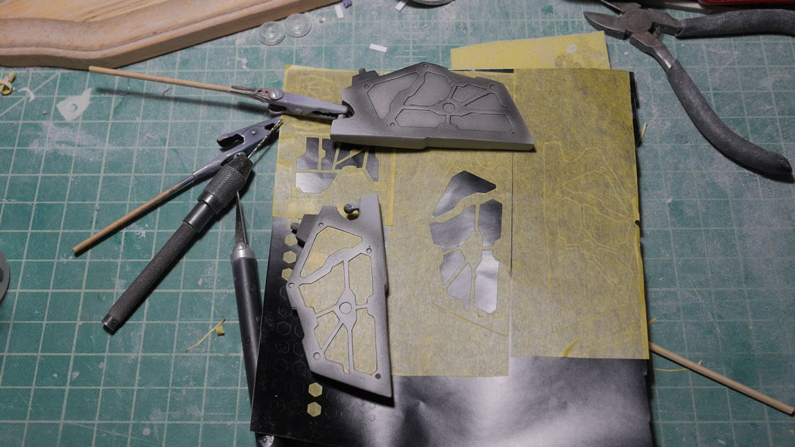
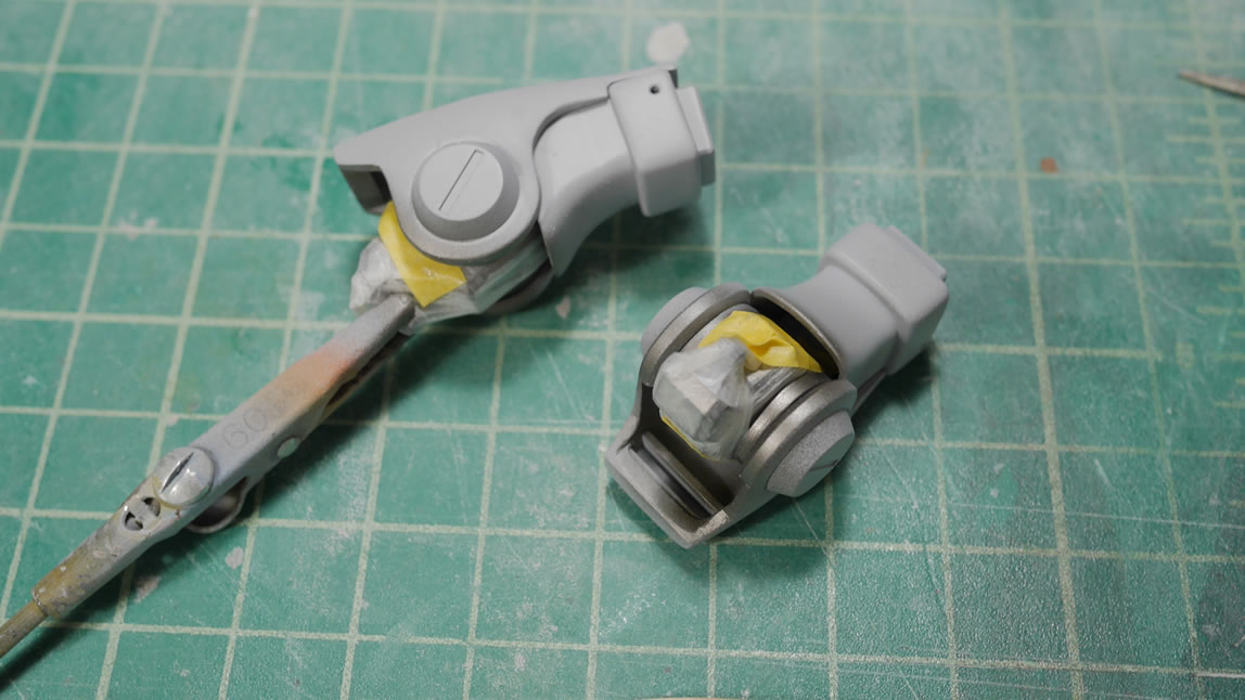
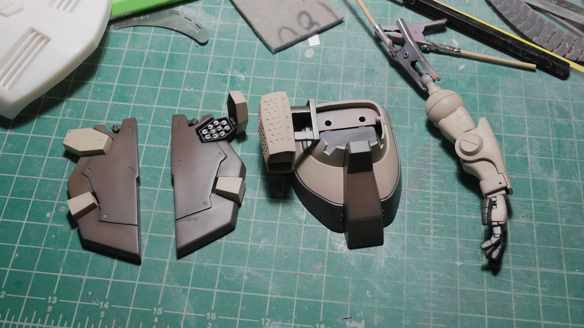
Now onto the exterior armor pieces. Again, I paint inside first then out. Since some of the parts are glued, I painted the internal frames first then glued the exterior armor to fix seams around the painted frames. These frames are then masked off so that the exterior armor can be painted.
Color choices. I’m going default color scheme so I grabbed some more screenshots from the game and tried to match the colors as best I could. Below are the paints I had. I then went and bought a bunch more paint after researching and comparing the colors more.
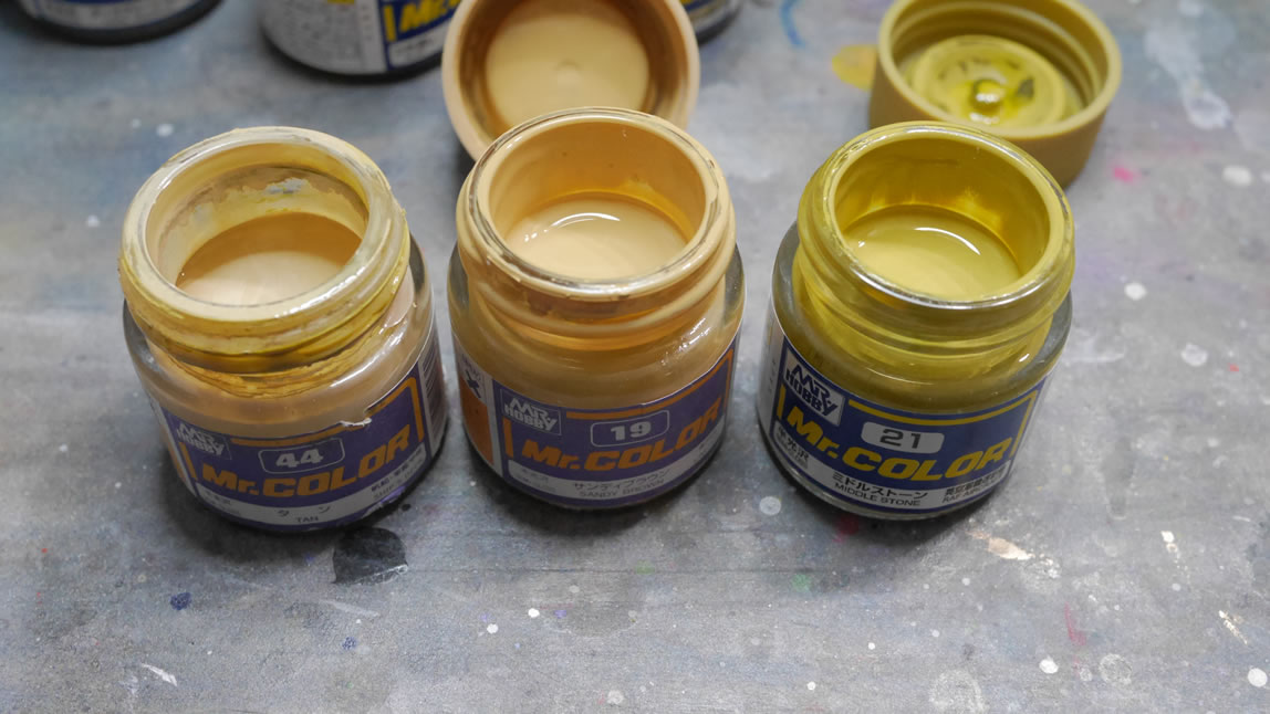
THe paint process I use is straight forward. Over the primed surface, I have the base color. Over the base color, I spray on white with fairly stark shadows. After this, the main colors are sprayed. For the arms, legs, missile pod covers and belt pieces, I started with Mr Color Brown (#7). White is then sprayed to create brown shaded armor pieces. The skirts and part of the foot are based coated in black followed by the white to shade it. The different colors give a different tonal effect to the final color. I also do this to create a color lift effect instead of just a stark dark tone under the final color. The top color effectively blends things together and I get a subtle shading effect.
The top layers of colors are sprayed and here’s the result. And with that, I noticed a problem in the left front skirt piece. There’s an uneven surface from the CA glue I used to attach the front skirt detail to the main skirt. CA glue is difficult to sand because it dries rock solid and is much harder than plastic, bondo, resin, etc. Do I fix this? Yes, I kind of have to.
The process to fix the issue is pretty simple. Starting with the part, I lightly sand the surface to give it a rough edge. Then light curing putty is applied with a putty knife to get a smooth surface. I’m basically building up the area around the hardened CA glue. Now, I could have gone the sanding method and just tried to level out the CA glue with a sanding stick or metal files. But sanding CA glue is like sanding a damn rock. So I thought it was less work to putty over it and then sand the surface smooth to remove the bump visual. With everything, there are multiple ways to do basically the same things; so it is only a matter of preference – or the easy way vs the hard way.
A quick sanding session to smooth things out, a primer session and a paint session. And done right?
Here’s a mock up of the parts. Notice that the left skirt (one I fixed above) is now darker in tone. The is an inherent problem with airbrush shading. It is VERY easy to spray too much paint over a part and get different tones. It is also why I tend to paint in major subsections like the arm, the leg, etc. So this will need to be fixed. The missile pods are glued into position so they need to be masked and for this fix, I just sprayed on some white to reshade the part white and painted over the white with the brown I had created for the skirts. This time, I sprayed slowly and constantly compared the part to the other skirt piece with each pass of paint so I could match the tone as best I could. The tone also slightly changes as it dries too.
I think I got pretty close. I have some pretty bright lights shining so every little defect can be seen. In regular everyday lighting, this should look decent.
Mistakes are everywhere. Especially when masking; you will miss spots, you will tear the mask. So accept this and just fix it. I remasked the back of the legs and painted in the metallics for the frame pieces that got painted with the exterior armor; and done.
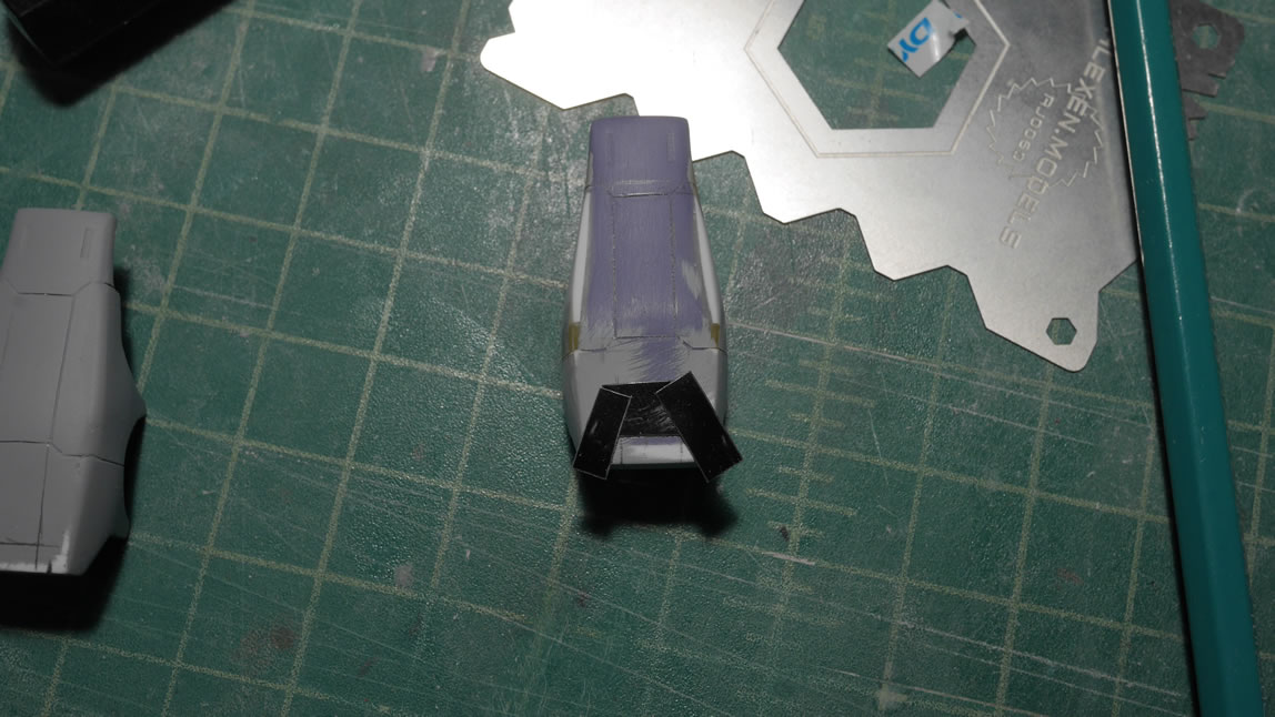
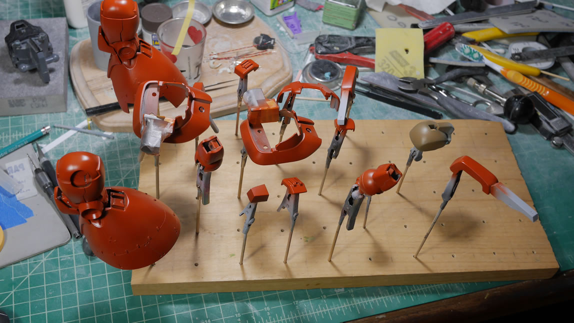
The head was repainted with the correct color scheme; early in the progress for the project, I finished the head first and got it all painted up. The problem was that I used a reference from pictures with an altered paint scheme so I wasn’t using the default scheme I reference now. So the head gets a repaint. The chest is base coated with Mr Color #7 brown and then sprayed with white. The cockpit hatch is the same color as the skirts, so that was painted first, and then masked off to paint the rest of the chest.
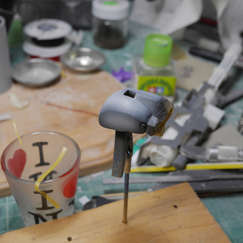
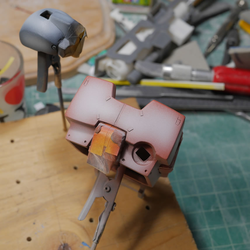
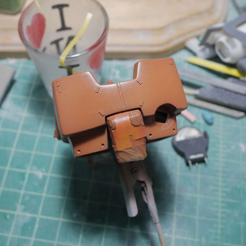
The last bit of work this weekend went to the bottoms of the feet. I added some photo etch details at the start of this post, so it makes for a nice bookend to this update that I finish with them. The round details were painted with alclad stainless steel over a gloss black base. The main thruster piece was painted with alclad burnt metal. That was masked off as well as the stainless steel rounds and the rest was painted free hand using alclad magnesium for the outer ring, alclad manifold exhaust for the first layer down, then the bottom layer and middle top sections were done with alclad steel. The thruster exterior is painted with alclad dark aluminum. At low pressure and spraying close, the airbrush can be quite precise and with practice, overspray can be minimized. The masking on the main thruster is removed and the center area was painted with alclad burnt iron. Some of the alclad colors have a very slight tonal variation which is what I was going for. I will definitely need to display this on a raise mirror base to show off some of these details. I didn’t bother painting the round vent details a different color as I think it works well in with the rest of that area. A panel line wash should help the details pop a little better. But I still have a ways before I get to that. The last bit of work was painting the shoulders. There are 5 colors for the shoulders which mean at least 4 layers of masking. So I’m in the middle of that process as I write this post.
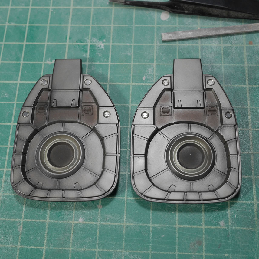
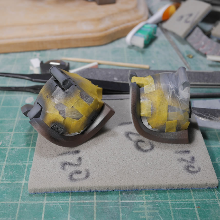
The project is coming along and the light at the end of the tunnel is getting much brighter now.
Juny 5, 2019: No update earlier this week since I went out of town for a quick vacation with the wife and corgis. My documentation didn’t stop before the trip, so I have some things that happened to the kit right before that and right after – most of what happened after anyways. Odds and ends are being worked on as the kit is in an odd limbo of different stages of paint. Some of the 3D printed parts need a decent amount of attention so there is work there to fix things. I also cut out a styrene frame for the rear skirt and that was glued to the base of the rear skirt. The shoulders were masked and painted and then masked and painted and then yet another level of masking and painting. Think inception for painting, start at the bottom layer first, then continue masking and painting until the very top layer; then unmasking everything layer by layer until you reach reality and spin your totem…
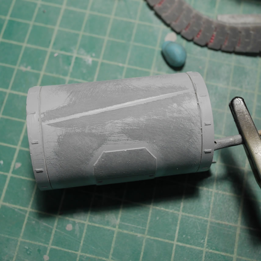
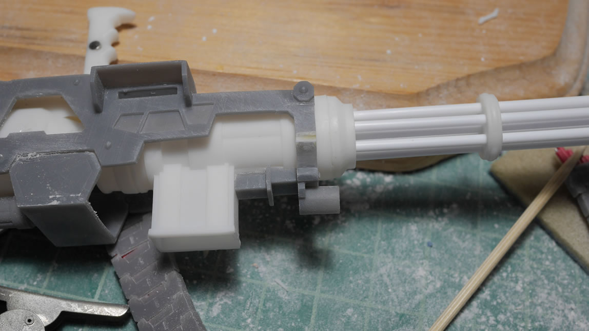
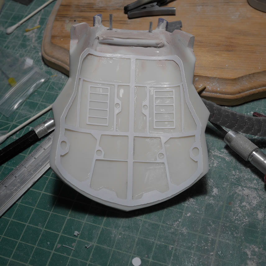
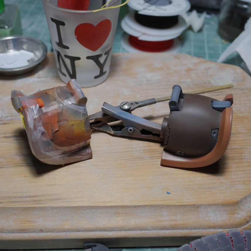
Aside from the underskirt frame detail, the bottom needed a little more work. I added a piece of plastic at the top as a sort of shelf. This also hides all the contact points to the waist piece and while I was upskirting the suit in the game (not creepy at all…) I saw this detail. The part is putted to make it look like it is part of the skirt and a notch for the center of the waist is cut so that the skirt fits with the waist frame. The sides of the skirt are puttied to blend the internal frame piece with the rest of the under skirt. The white of the resin with the partially sanded primer and the light curing putty look pretty cool under the UV lights used to cure the putty.
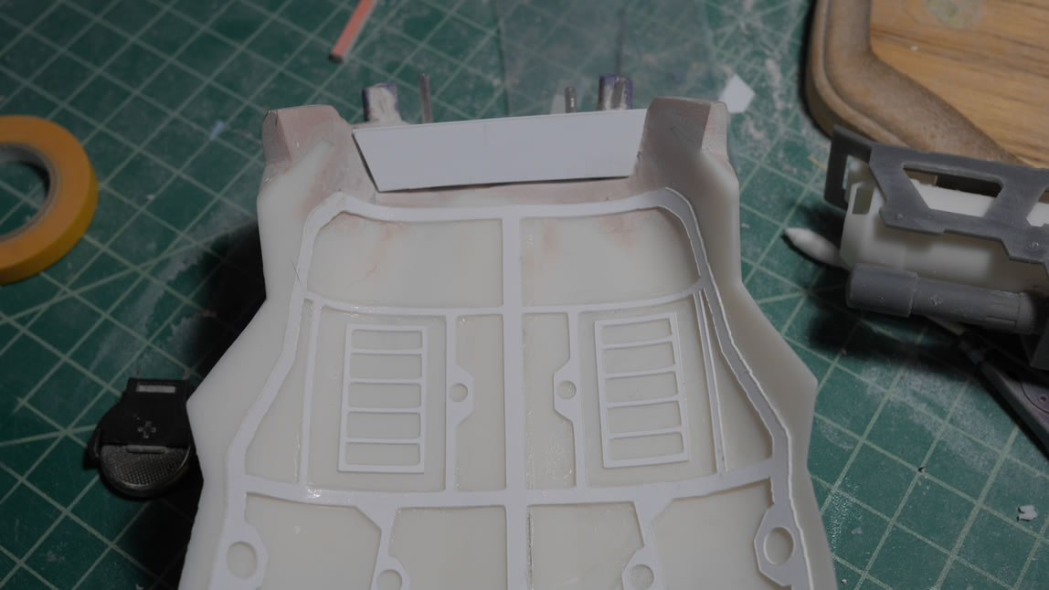
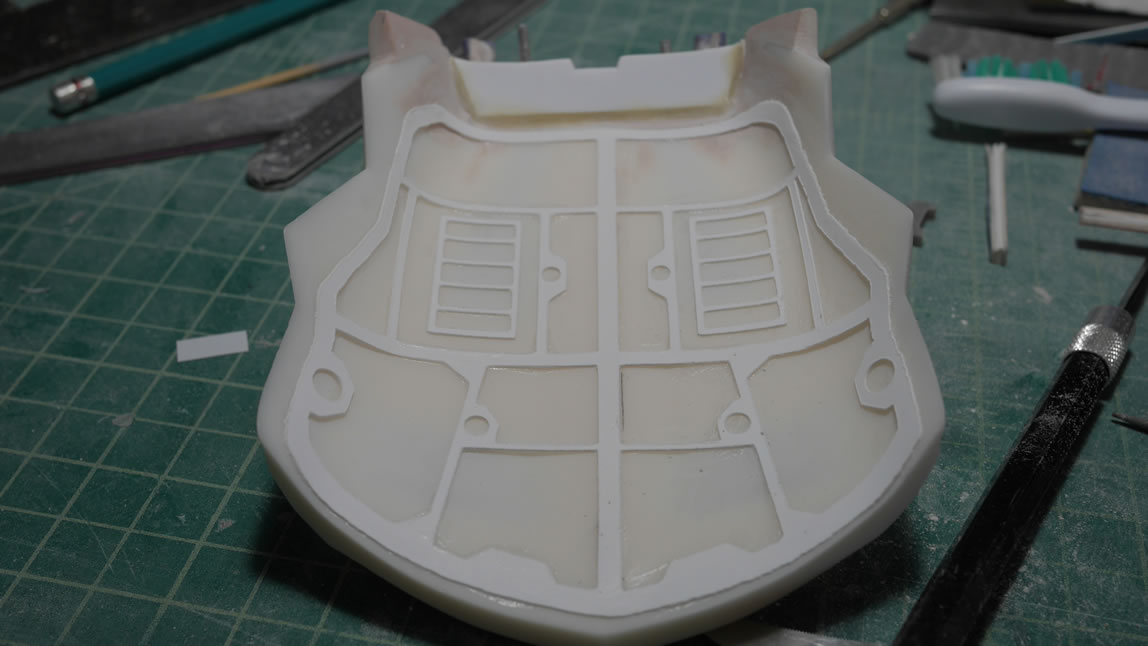
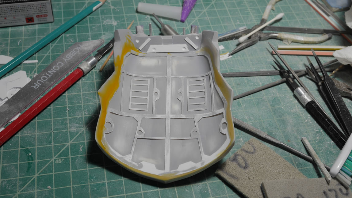
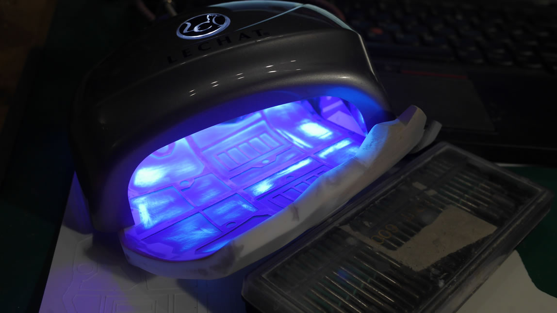
Once cured, the putty is sanded and the top sides of the skirt are also sanded to remove the rough spots and fill any other defects. Primer shows a pretty good finish so I can get to painting. There are still issues with the underskirt, but since it IS the underskirt, I’m not too worried about perfection here. I just need this to be good enough for my standards – which are pretty low to start.
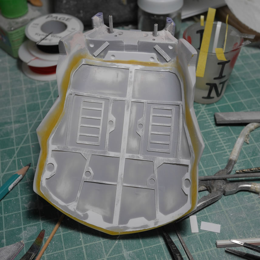
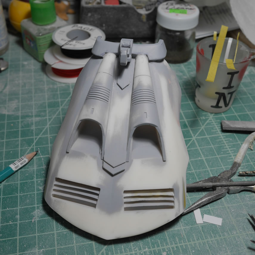
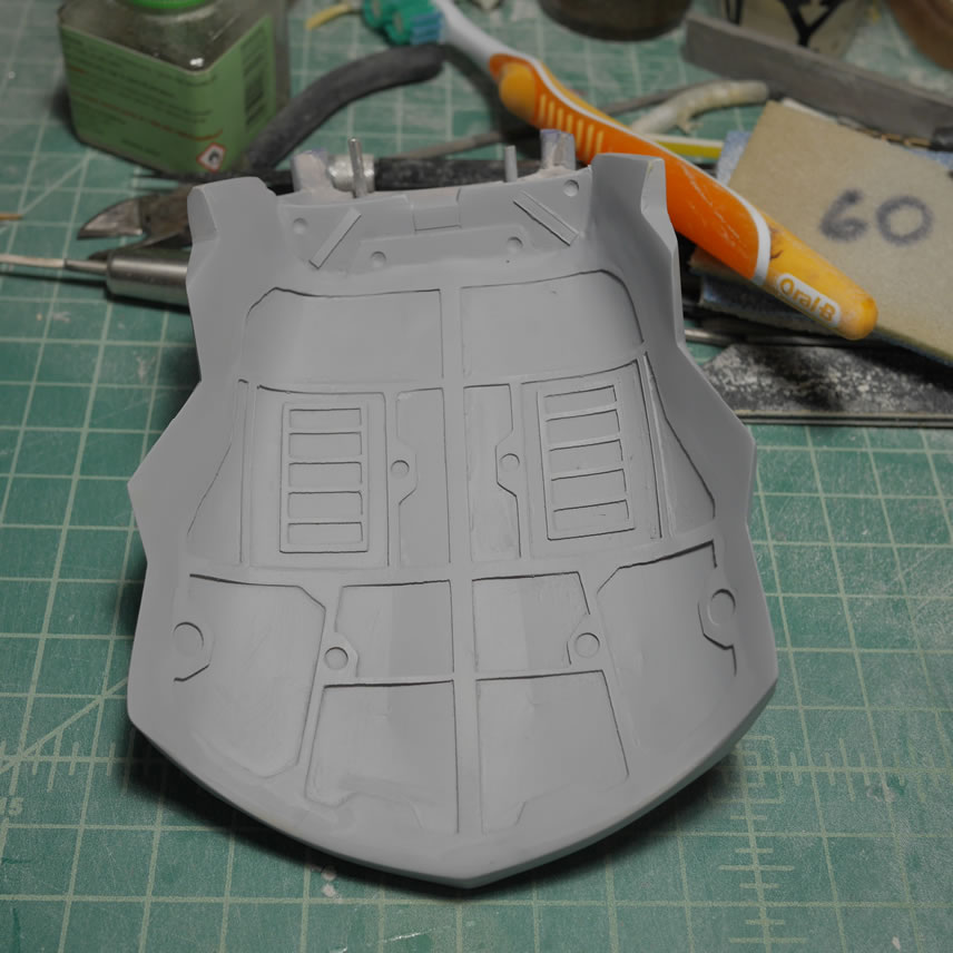
The gun is primed and some areas have dents that need to be addressed. Similar dents can be seen in the first picture of this post for the ammo canister. Light curing putty comes to the rescue here and the ammo can piece too and those areas are puttied and sanded.
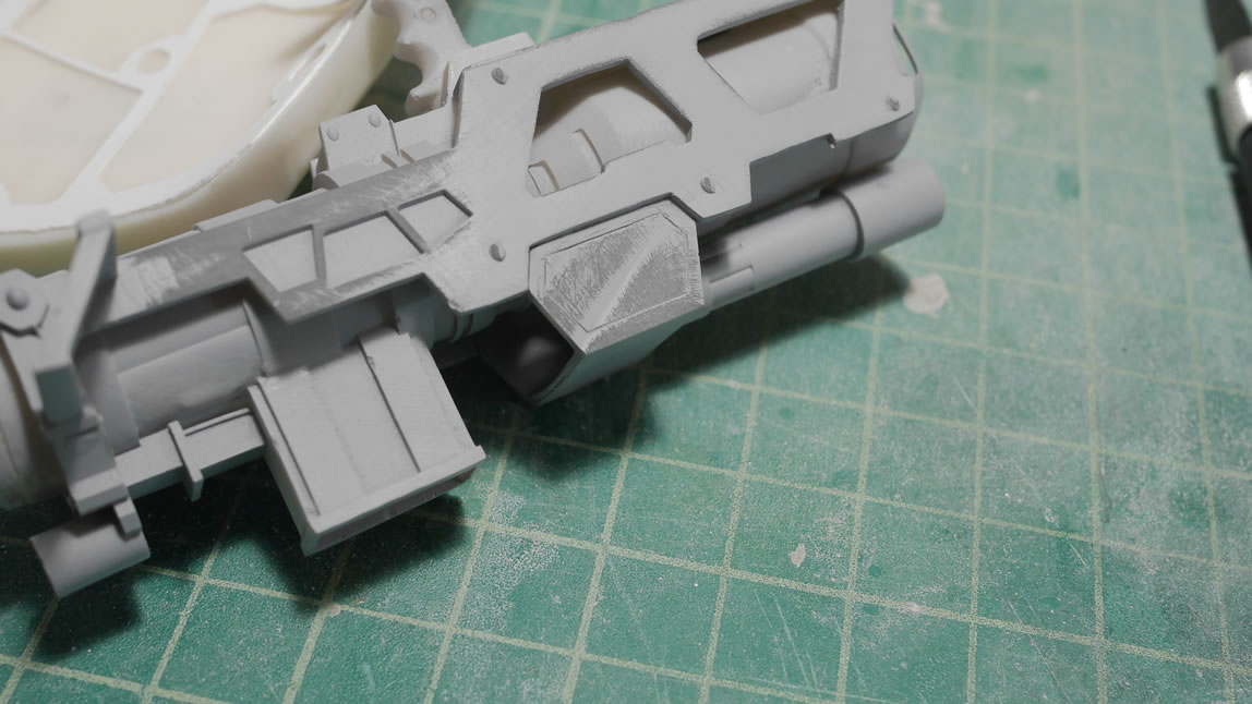
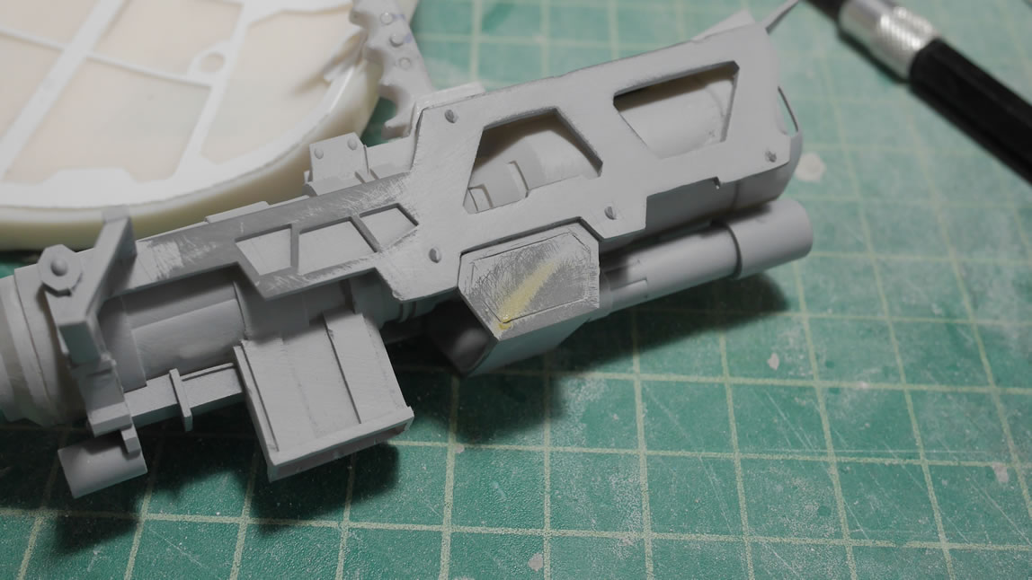
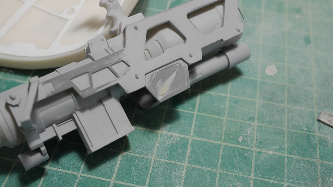
The rest of the kit gets a quick test fit to make sure things are looking ok. And the ammo belt is disassembled and painted.
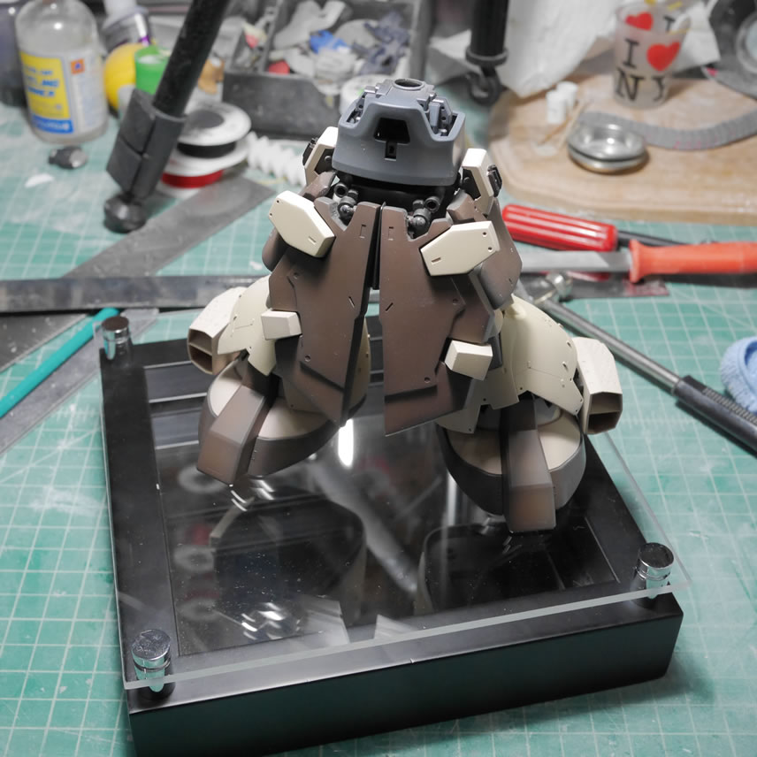
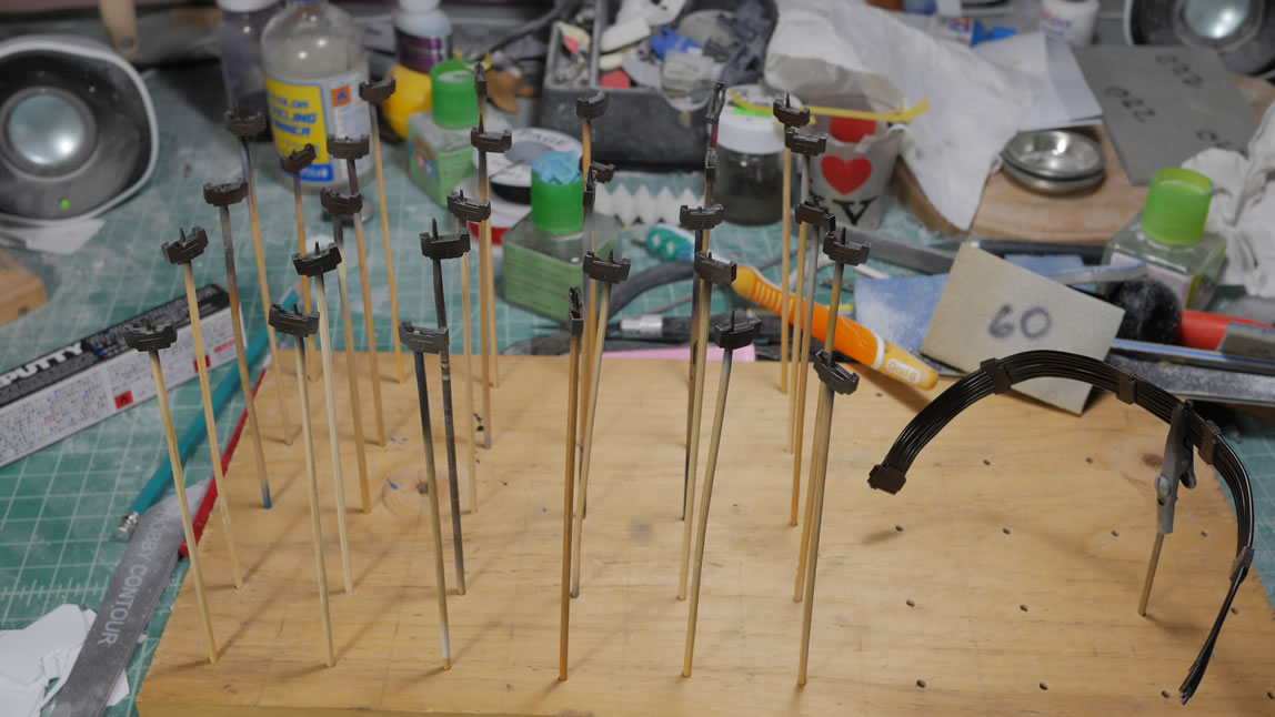
Most of the parts are painted and drying/curing with a help of a dehydrator. The dehydrator is a HUGE time saver and help cut down the dry times I used to have between paint layers.
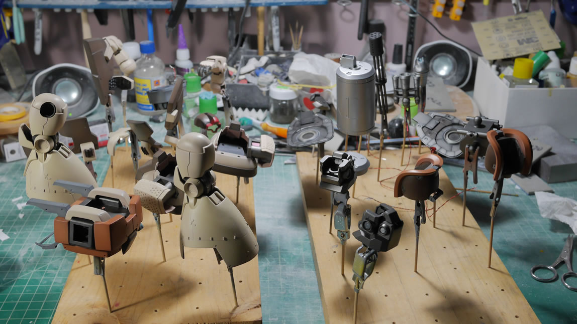
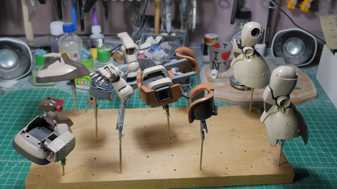
A clear gloss is sprayed onto the parts to prep them for the decal process.
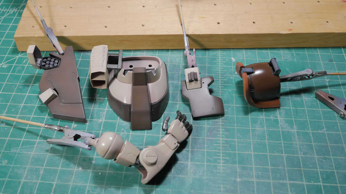
The decals sheets are brought out and I sift through them to find the appropriate misworded/spelled warning labels to use on the Dom. I may have gone a little overboard, there are 22 individual decals on the chest piece. Ver Ka style decaling I guess – it’s all the rage with the gunpla builders.
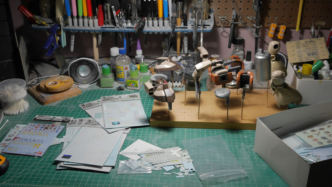
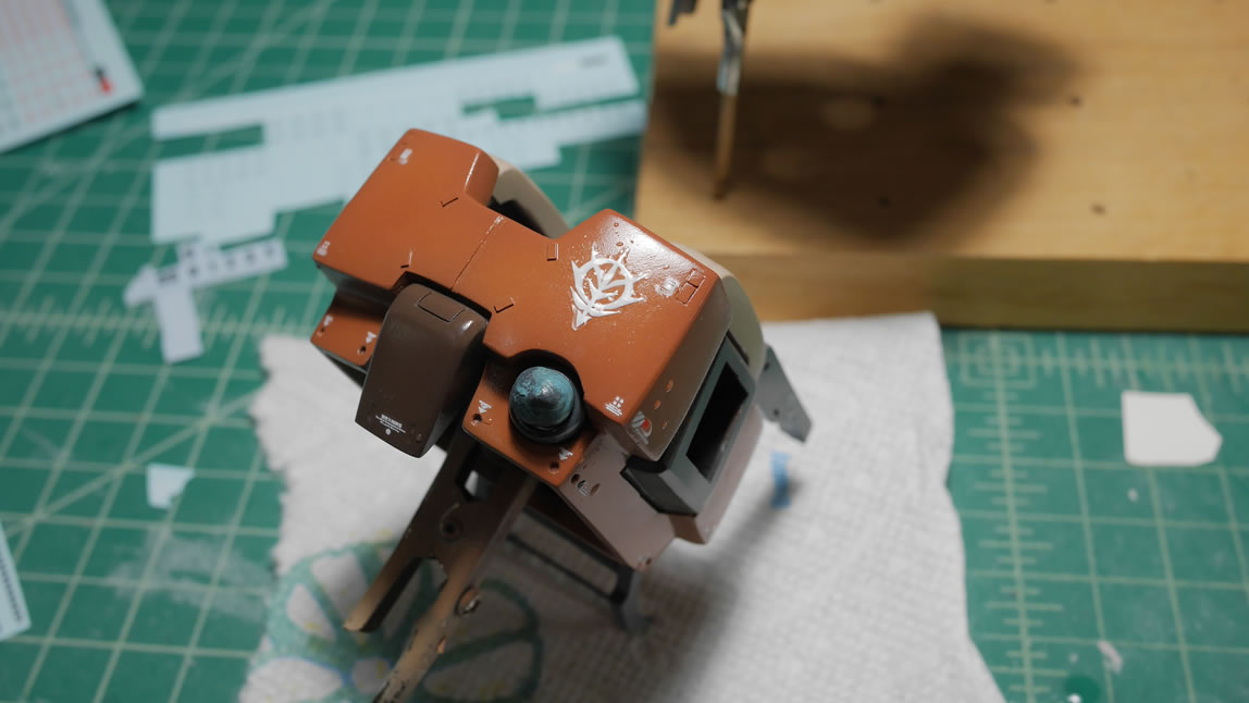
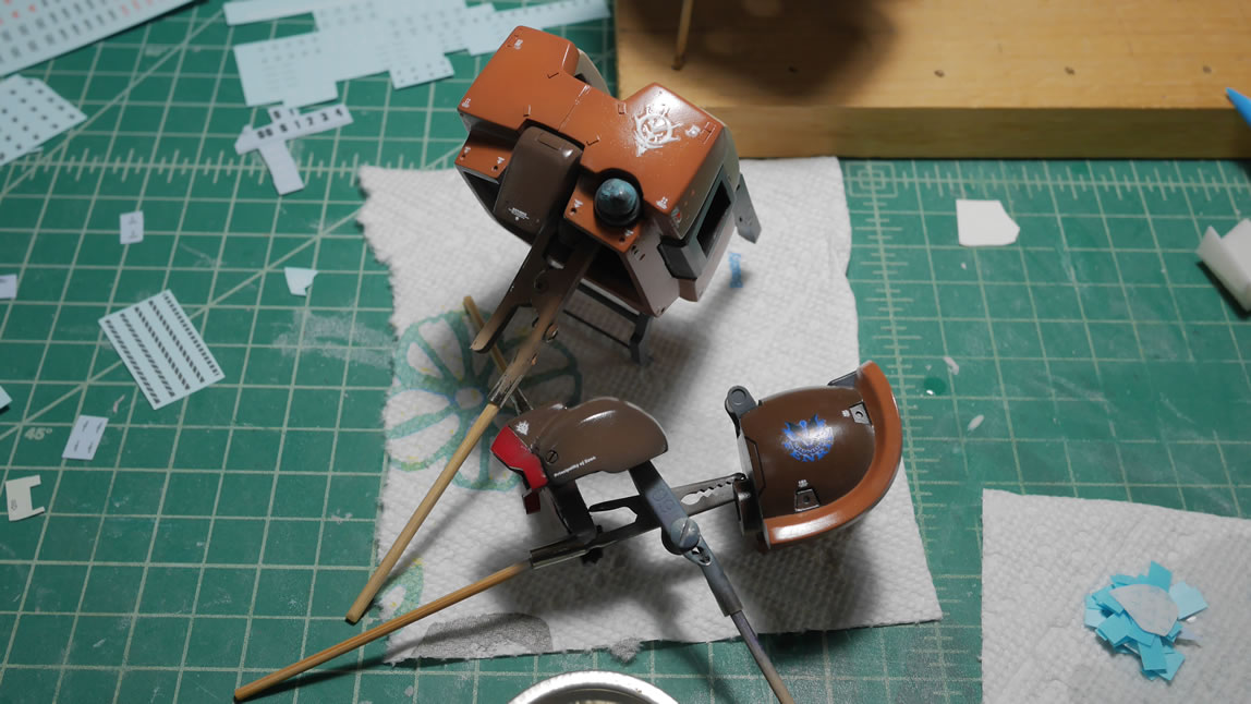
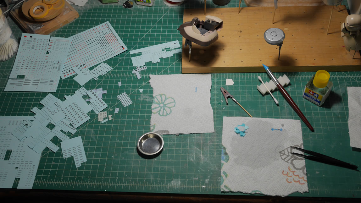
Once decaled, I have a arm comparison for the before and after.
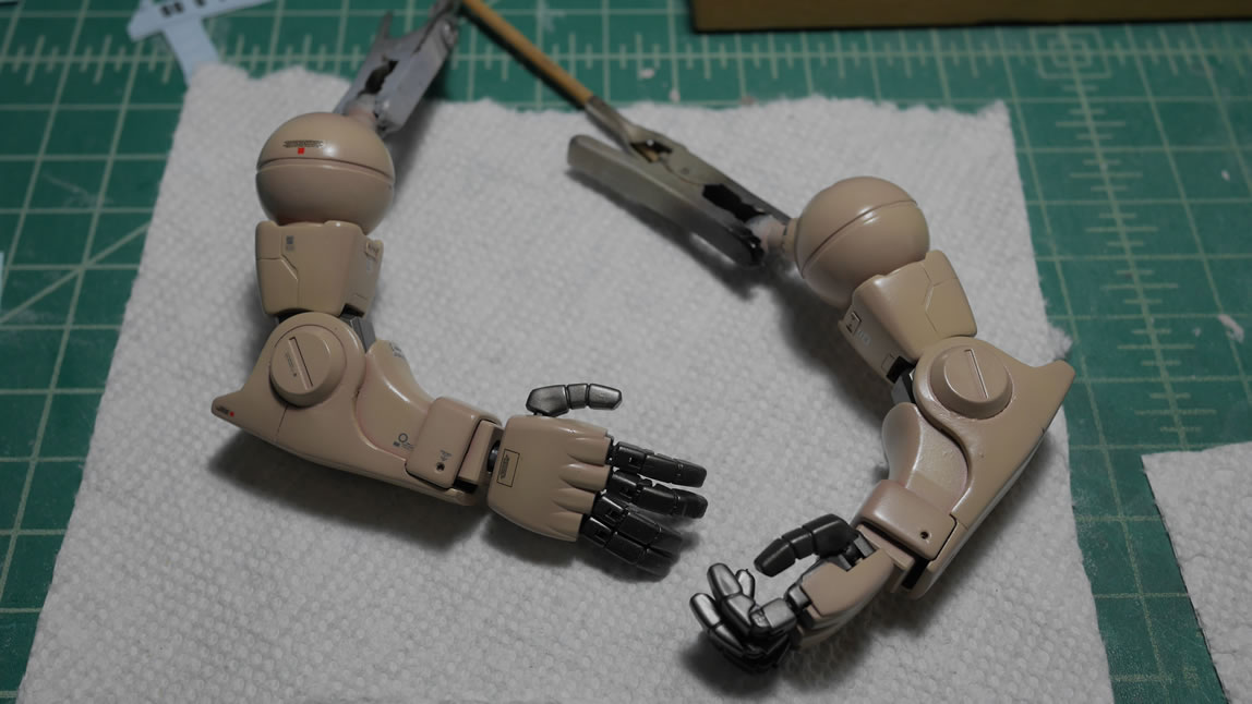
The skirt is painted and masked, and painted and masked some more to finish painting the entire rear skirt.
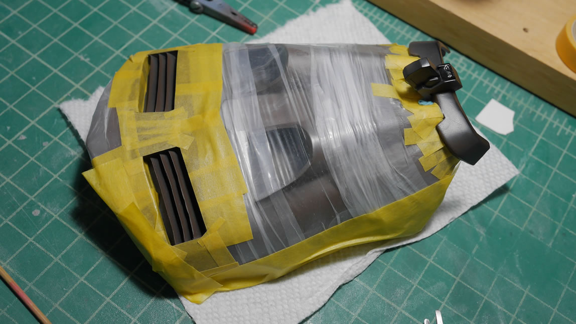
I did a quick light test using a battery and a reed switch. The process is pretty simple, the reed switch is magnetically operated as the two contacts inside the glass tube are attracted to one another in the presence of a magnet which completes the circuit and turns on the LEDs.
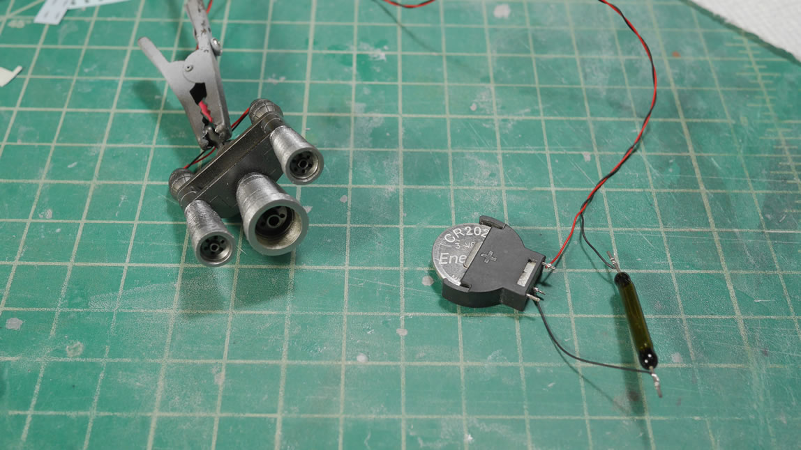
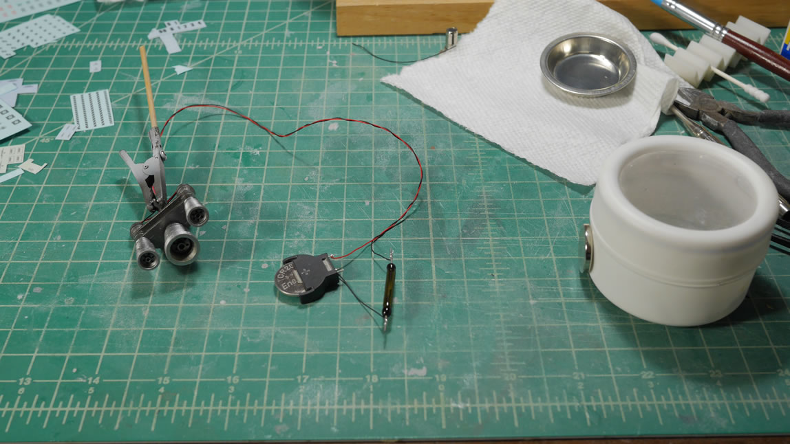

Another gloss coat is applied to sandwich the decals and help hide the decal lines. Once that cures, it’s time for the panel lining which brings out all the little details – especially those in the photoetch accent pieces.
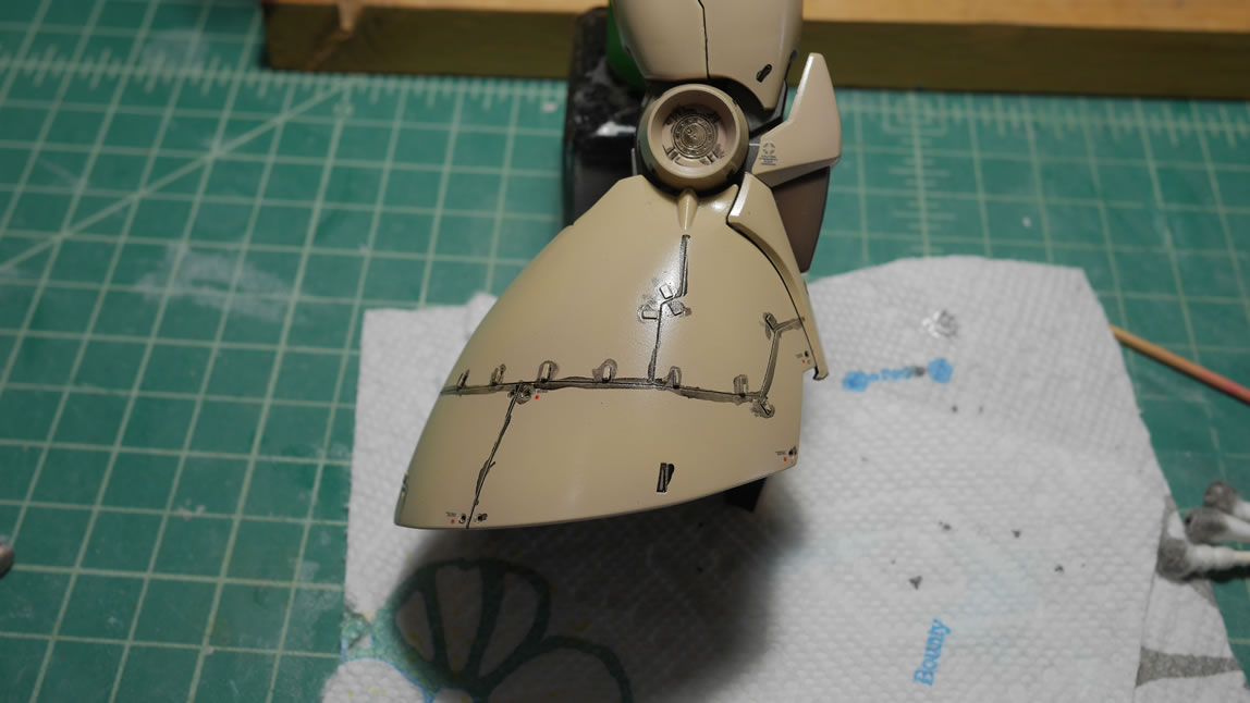
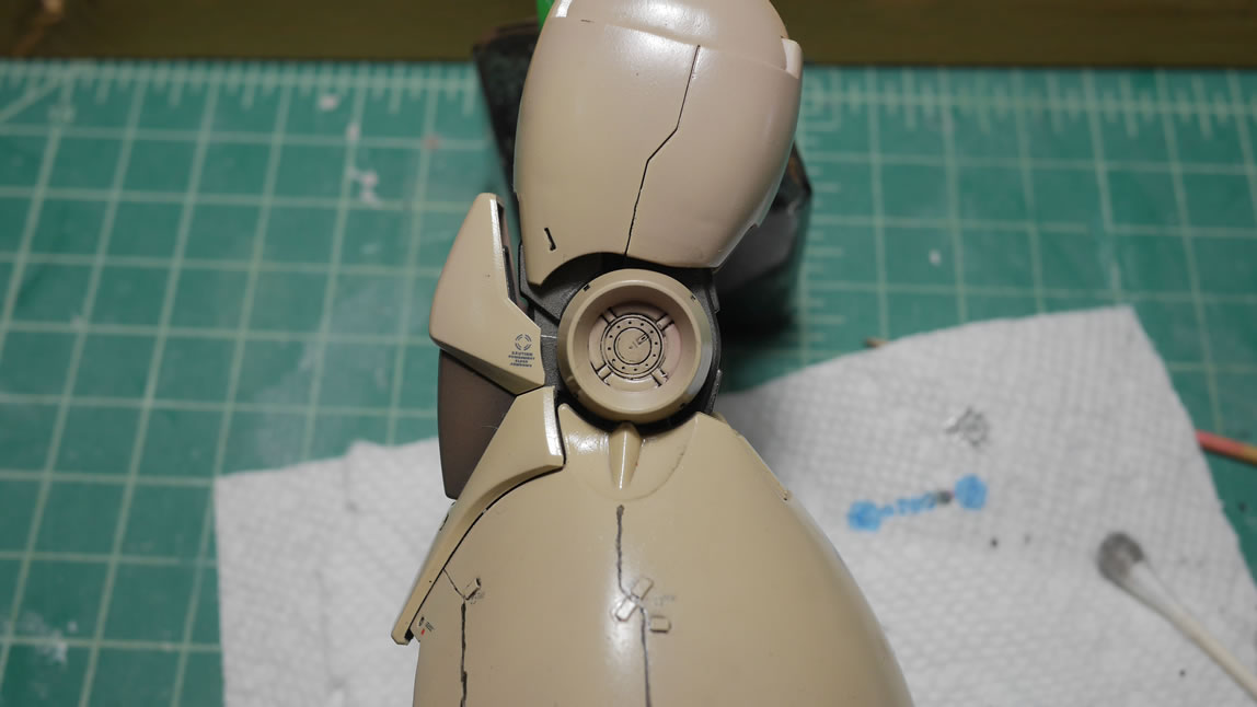
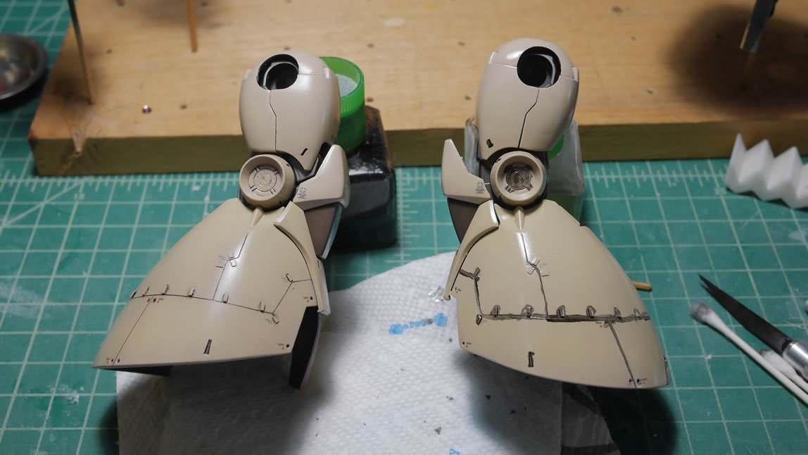
This past Wednesday night, I started working on getting the electronics combined. Batteries and reed switches are placed around the kit, 1 in each foot and one set in the chest. And after successful tests, the wiring is soldered together and it’s about ready to final assembly; sort of.
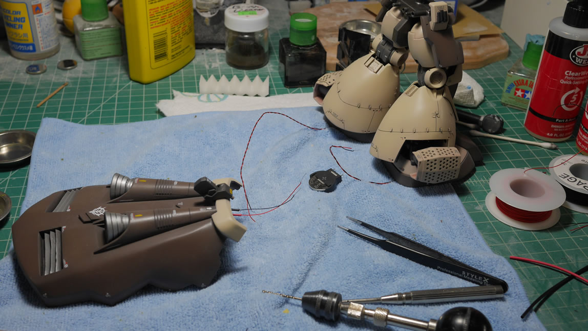
Here is the assembly process. Too focused to take more pictures since it was pushing 2AM Thursday morning.
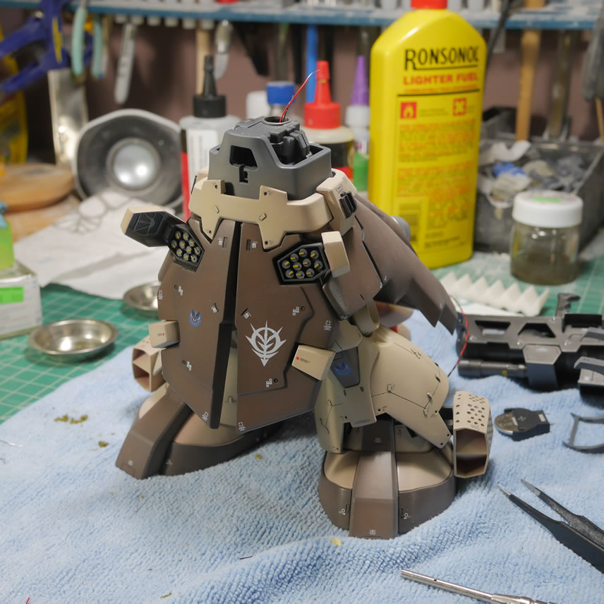
Pictures stop here because I was more focused on finishing the project for AX than anything. But my rushing has resulted in some problems that will need to be addressed when I get the kit back from being displayed at Anime Expo 2019. I’m not a perfectionist, and I can live with the mistakes, I just wanted it in the case so I didn’t have to worry about it and sorta enjoy the rest of the week at AX. Once I get it back, I will probably apply a slight bit of weathering just to complete it. The kit just feels like it should be weathered; not necessarily heavily, but at least SOME weathering. And my screwed up decal can sorta help with that.
July 12, 2019: As promised, there were only a few last steps for this project. The kit has been broken down into major subsections. Some subsections bigger than others. And I start off with applying some paint chipping using an enamel based metallic grey. A very small brush is used and I just slowly and carefully apply some chips here and there. I don’t want to go overboard, I just want to see that the suit has seen “some” use.
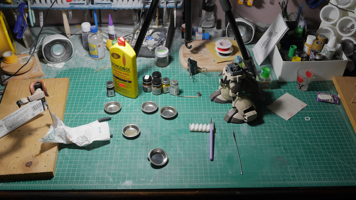
The arms are paint chipped and I have one that wasn’t touch as a comparison to one that I started weathering. It is a very slight touch of chipping. Next up I clear glossed the parts and started in on the filter.
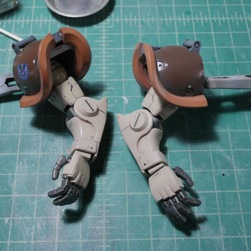
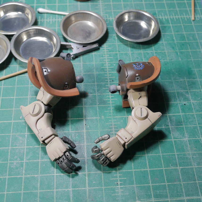
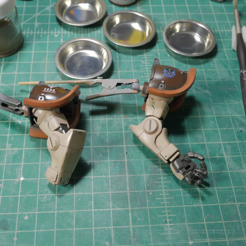
The filter is composed of 3 main paints, zinc (yellow), white, and dark earth. A 4th color of rust is added but only in small select areas. Once the parts are dotted up, I take a stiff brush and lighter fluid and proceed to wipe away the dots creating a blended faded effect that changes the tons of the parts.
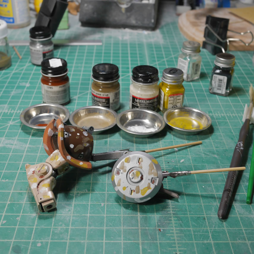
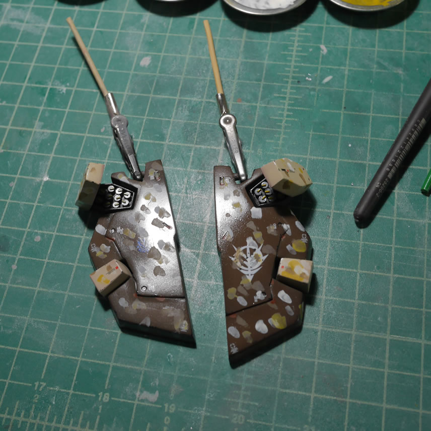
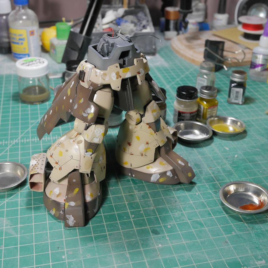
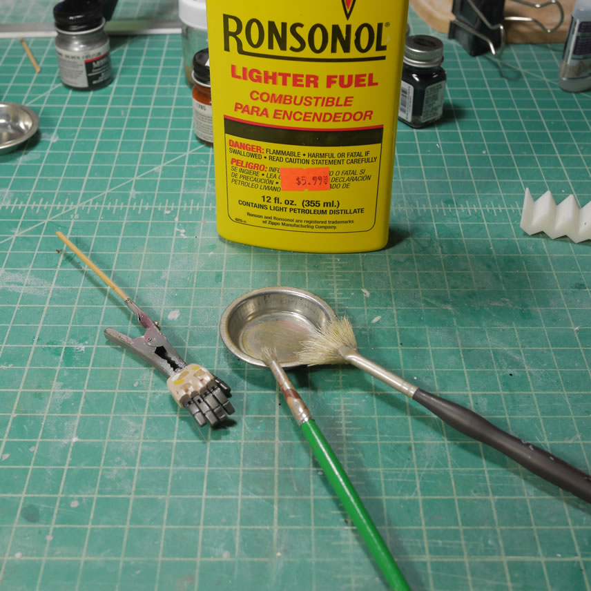
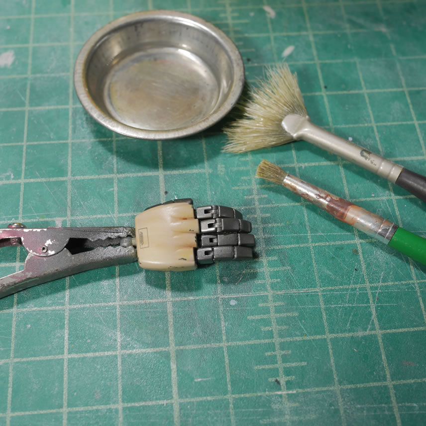
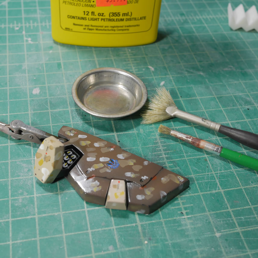
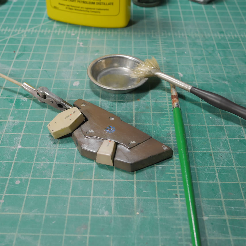
Light fluid works very well. I had some problems removing the white so I dipped my brush into some testor enamel thinner and that stuff was WAY too strong and started removing a little too many layers. I think I salvaged it a bit, but the right side of the rear skirt took the brunt of that mistake. Below is a quick picture of where I stopped with the filter on these parts.
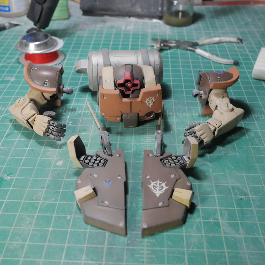
A few updates ago when I glued the smaller missile pods into position, I failed in test fitting and test functioning the opening mechanics of those pods. Had I did it correctly, I wouldn’t have had the problem I had now. Those doors did not open, or if they did, they barely opened. The back of the pods did not have enough room. I left this as is and just figured I’d only open the bigger missile pods. While doing the weathering, the fact that I spend considerable time designing and working on the smaller pod doors, it just ate at me because it seemed a complete waste if I didn’t go and just fix it. Last night, I couldn’t sleep so I got out of bed and started chiseling away the excess plastic making room for the pod doors to open. Here is a comparison with one of the doors before and after.
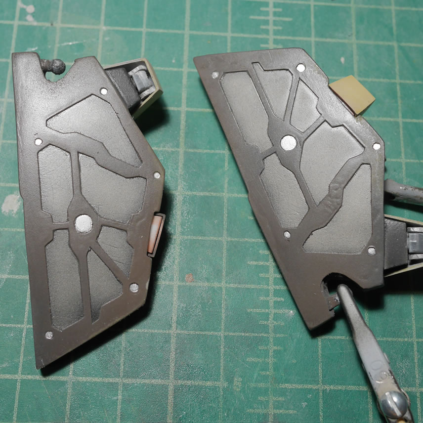
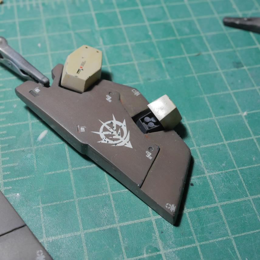
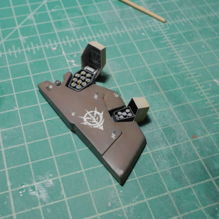
The BMC 2mm chisel is used to scrape away plastic slowly and in a fairly straight edge. Once that was done, the other side was fixed and then lightly sanded.
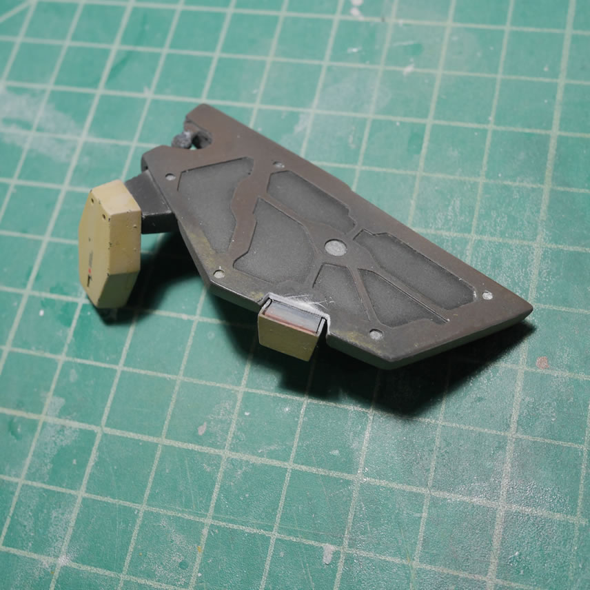
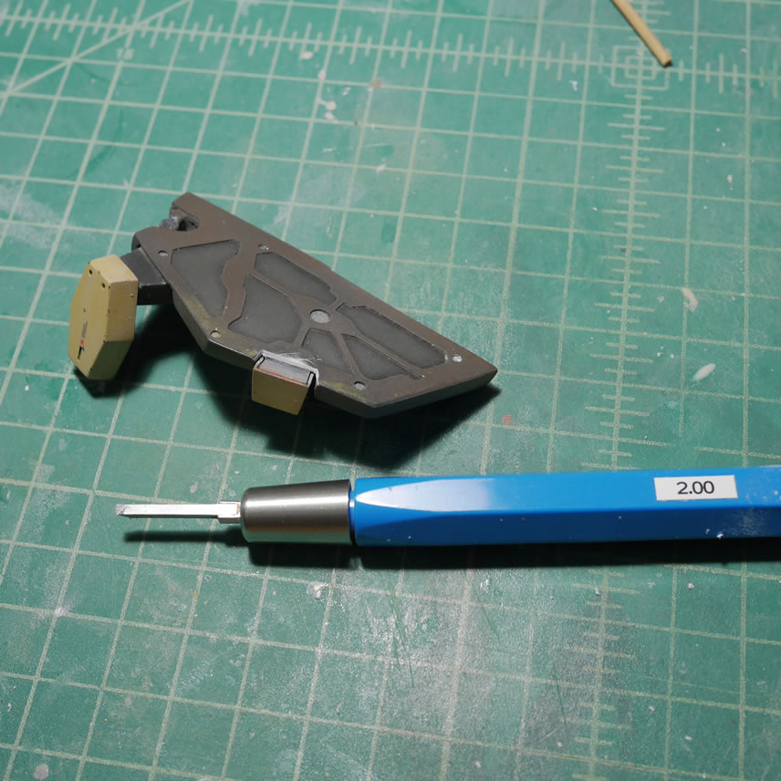
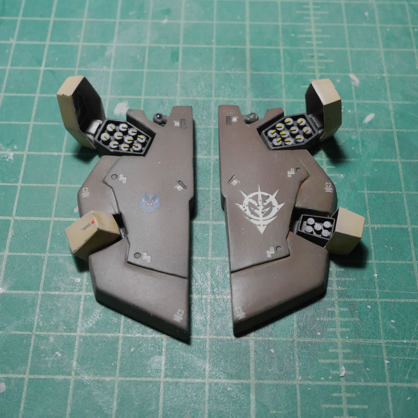
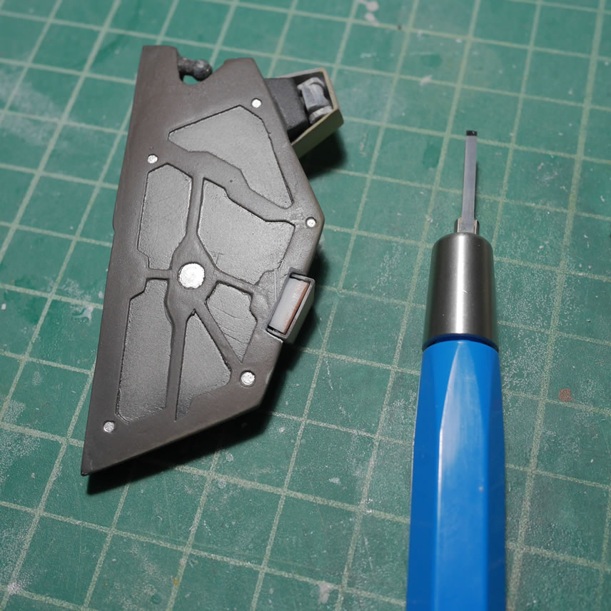
Both doors work so I added some details to the missile pods and painted the repaired area as well as the missile pod details.
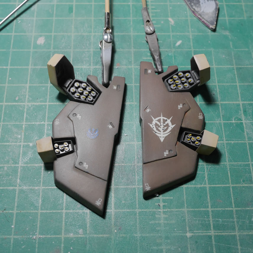
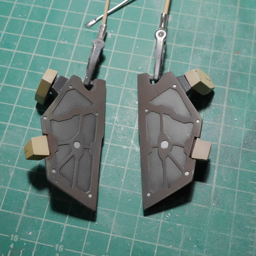
Today, after a clear flat sprayed last night over the dried filtered pieces, I applied the tamiya makeup kits and did some pigment weathering for the kit.