May 7, 2018: Our theme for this year’s SCGMC is the Bearguy, so I’m finally getting off my ass and starting up my Bearguy project. I think I may have bitten off more than I can chew at this time. Sometimes when inspiration hits you, it’s like being hit by a motorcycle speeding from your blind spot. You’re not expecting it at all, and *WHAM* the ideas just start flowing. I had been working on the Grim Reaper figure kit and I just had to pull a complete stop. The force is strong with this one and cannot be ignored. Little Miss Reaper joins the rest of the projects in various modes of development hell.
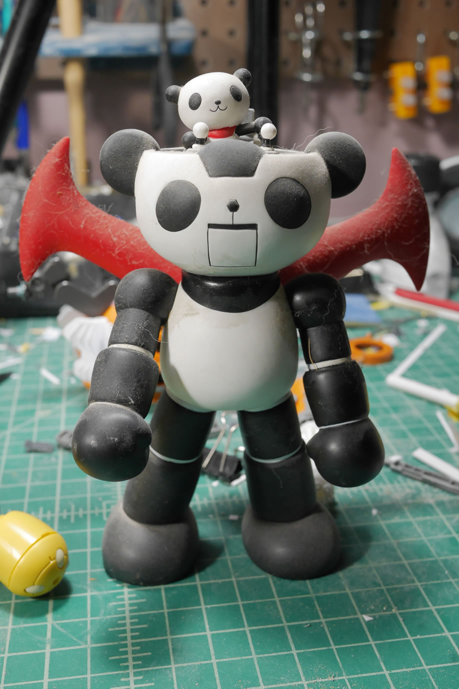
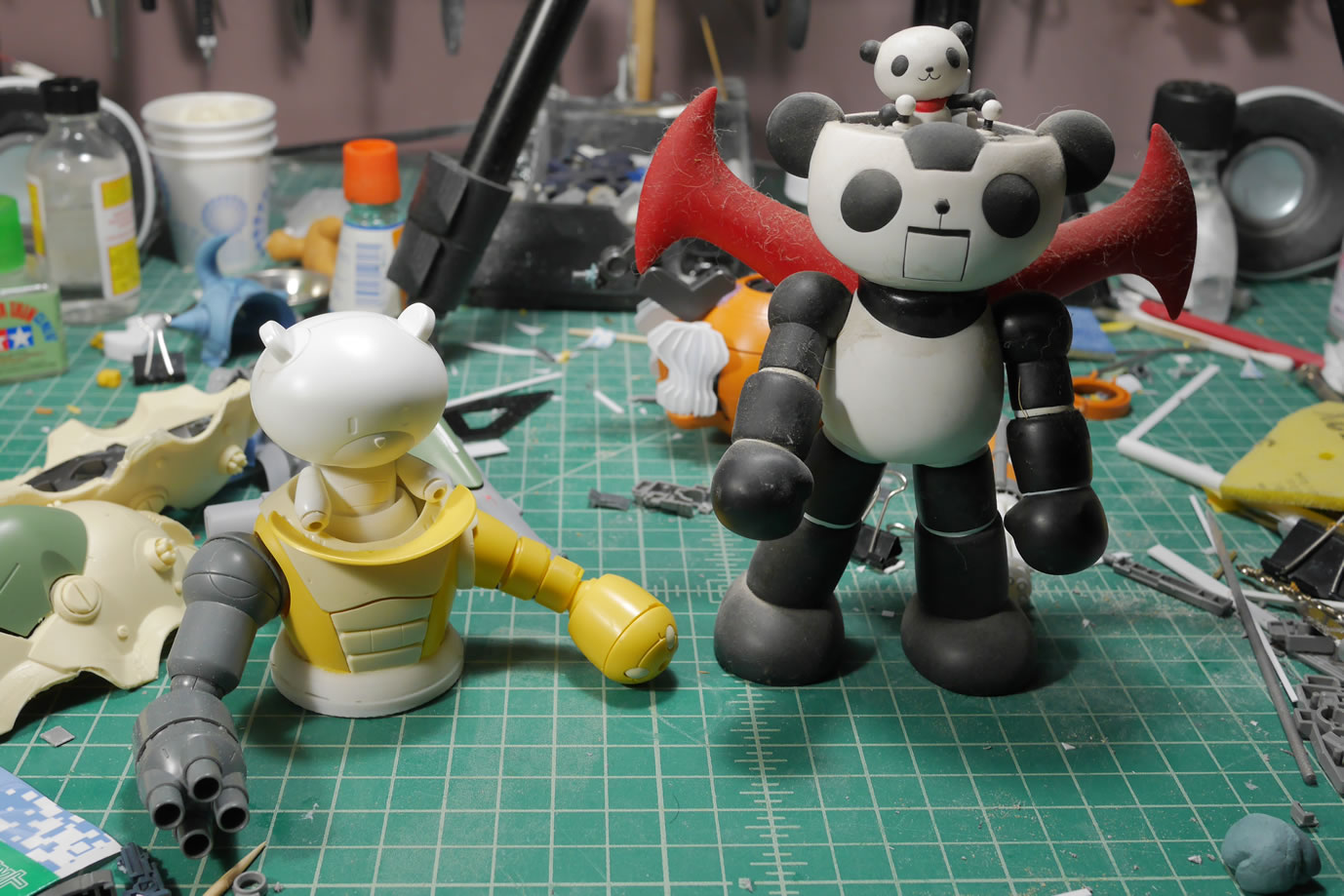
Way back when the first Bearguy came out, I had an idea of fitting the kit (1/144) inside an MG Acguy (1/100). The idea stems from the Panda-Z anime/toy that I picked up almost 20 years ago. The idea floated around for a while then just faded away into the back of my subconscious with the rest of the half-witted ideas I get. Then comes the Petit-Bearguys and the idea slightly resurfaced, but was quickly overruled by other projects in progress or of higher priority. Fast Forward to the end of last year when we announced our 2018 SCGMC Theme and add a few months before the true inspiration that really kickstarts the project.
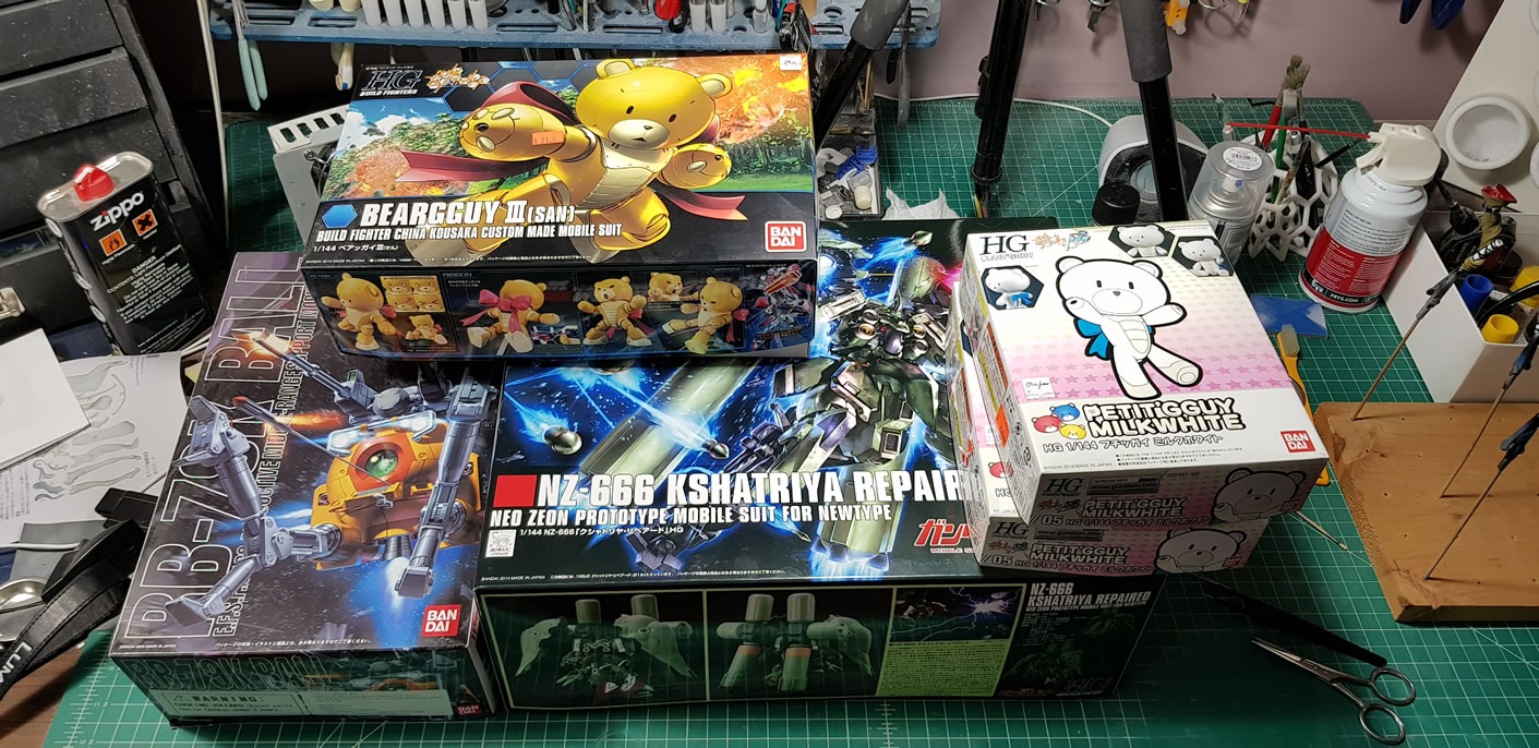
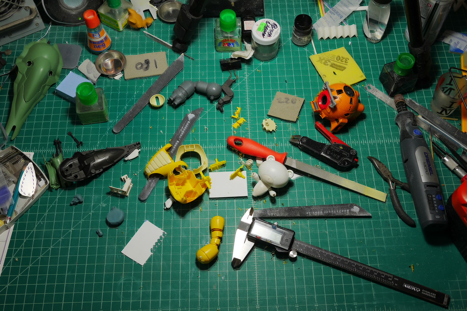
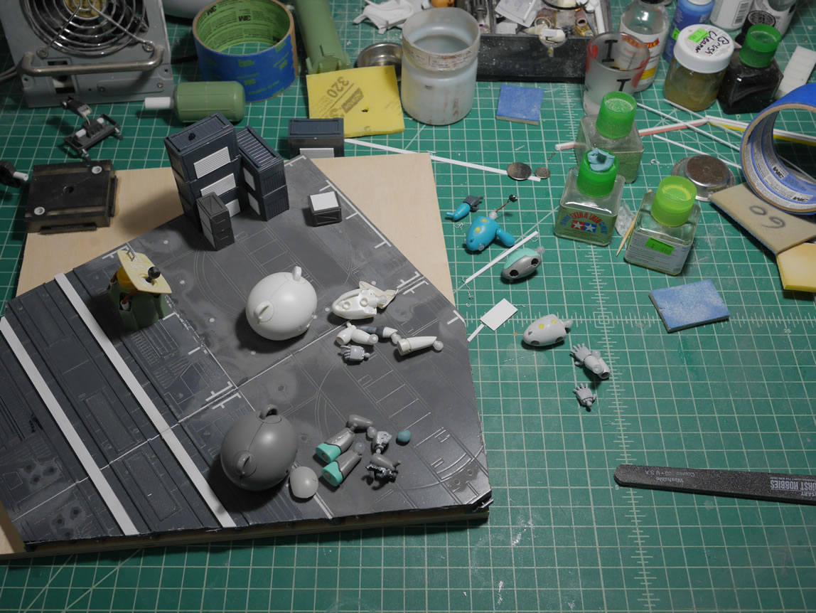
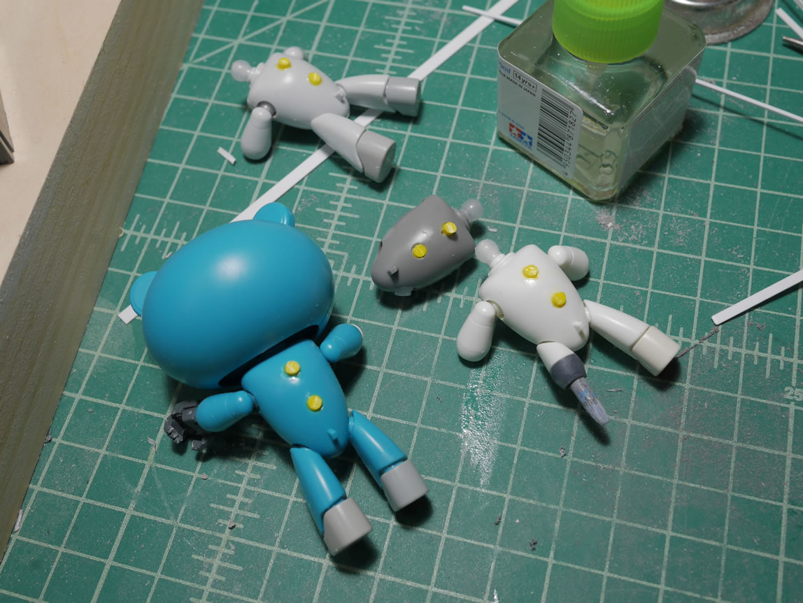
Aside from the Panda-Z, I’m also inspired by the giant Omni-droid from Incredibles. First step is to acquire the kits my imagination pulled together, so we have the 1/144 Kshatriya, the Bearguy San, an MG Ball, and a Petit-Bearguy. The arm of the MG Guntank was an afterthought so not really one of the full kits being used; I’ve already been cannibalizing that kit for several other projects; so what can one more do to hurt? The main pieces from the kits are quickly snapped together so I have a very rough idea of what I’m planning on bashing together.
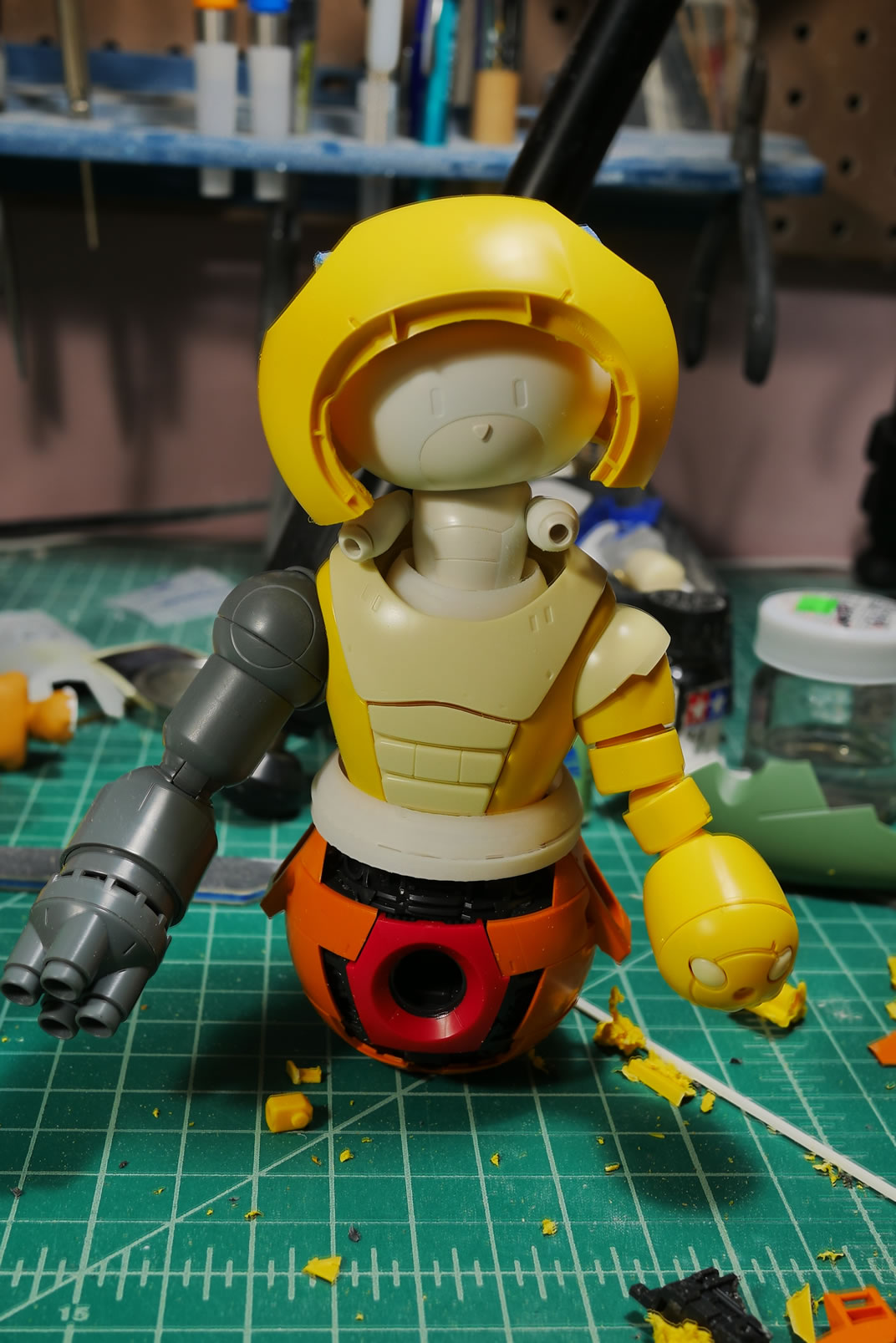
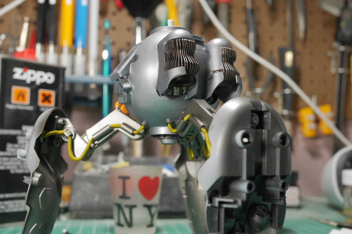
What I end up with is the Petit-Bearguy (PBG) as the driver of an upper torso of the Bear-Guy (BG) with a lower torso of the MG Ball, and the Kshatriya (K) binders as legs in a tripod configuration.
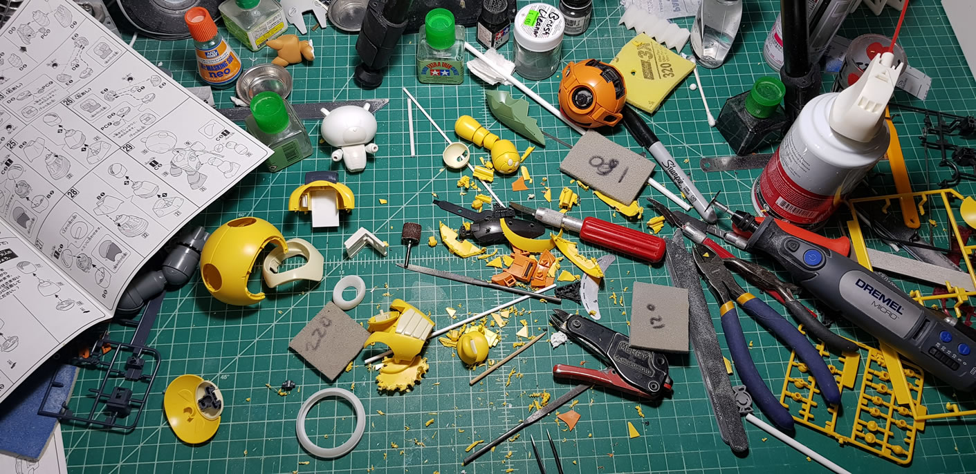
This project started near the end of March, and I’m only just now getting around to making a post because I actually have a fairly decent progress flow. So after the jump, this wall of text and pictures taken over the past month continues. A snide note, I used a bad option on my camera that pretty much ruined a good number of pictures. So the different resolution size are pictures from my camera phone and what pictures I was able to salvage.
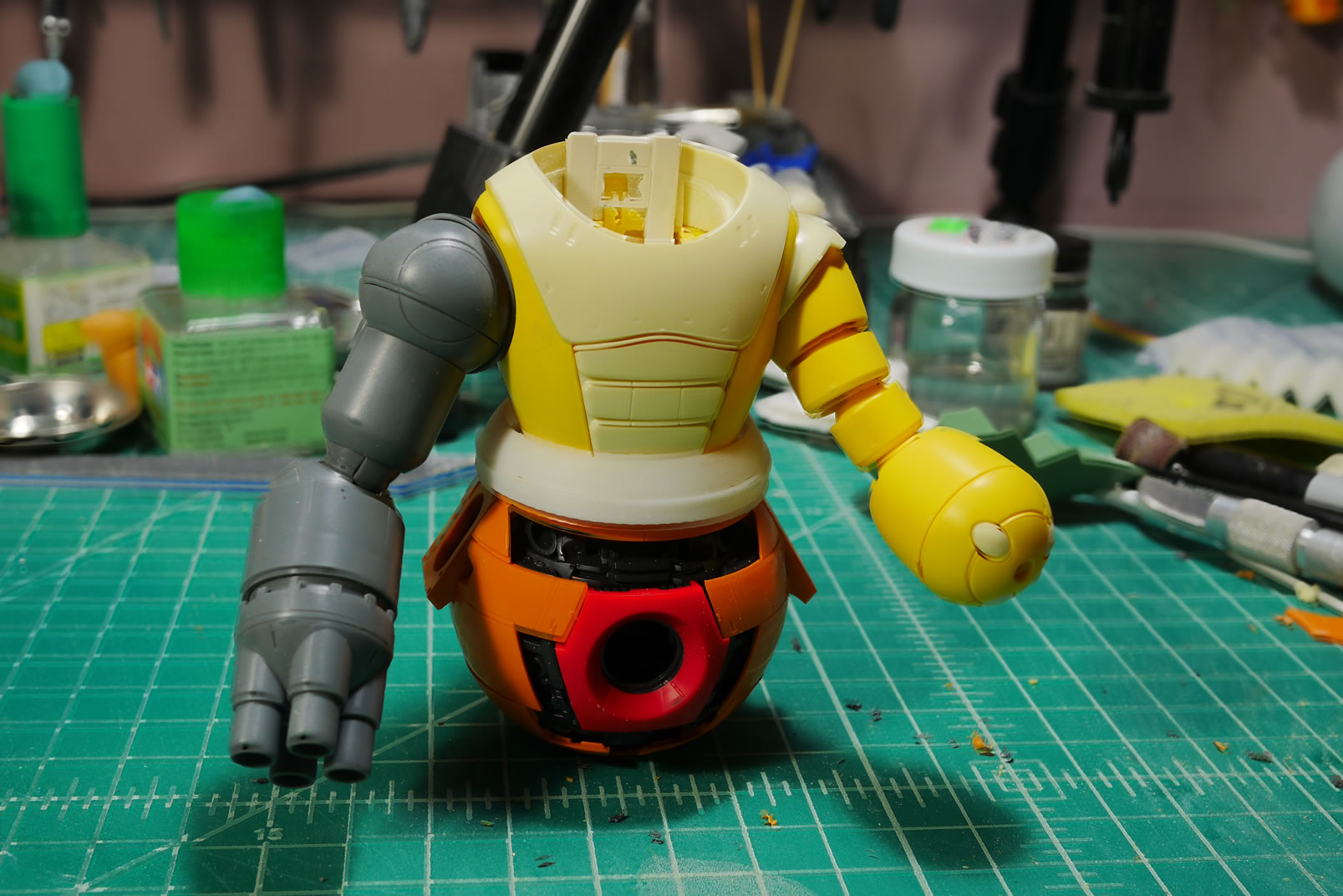
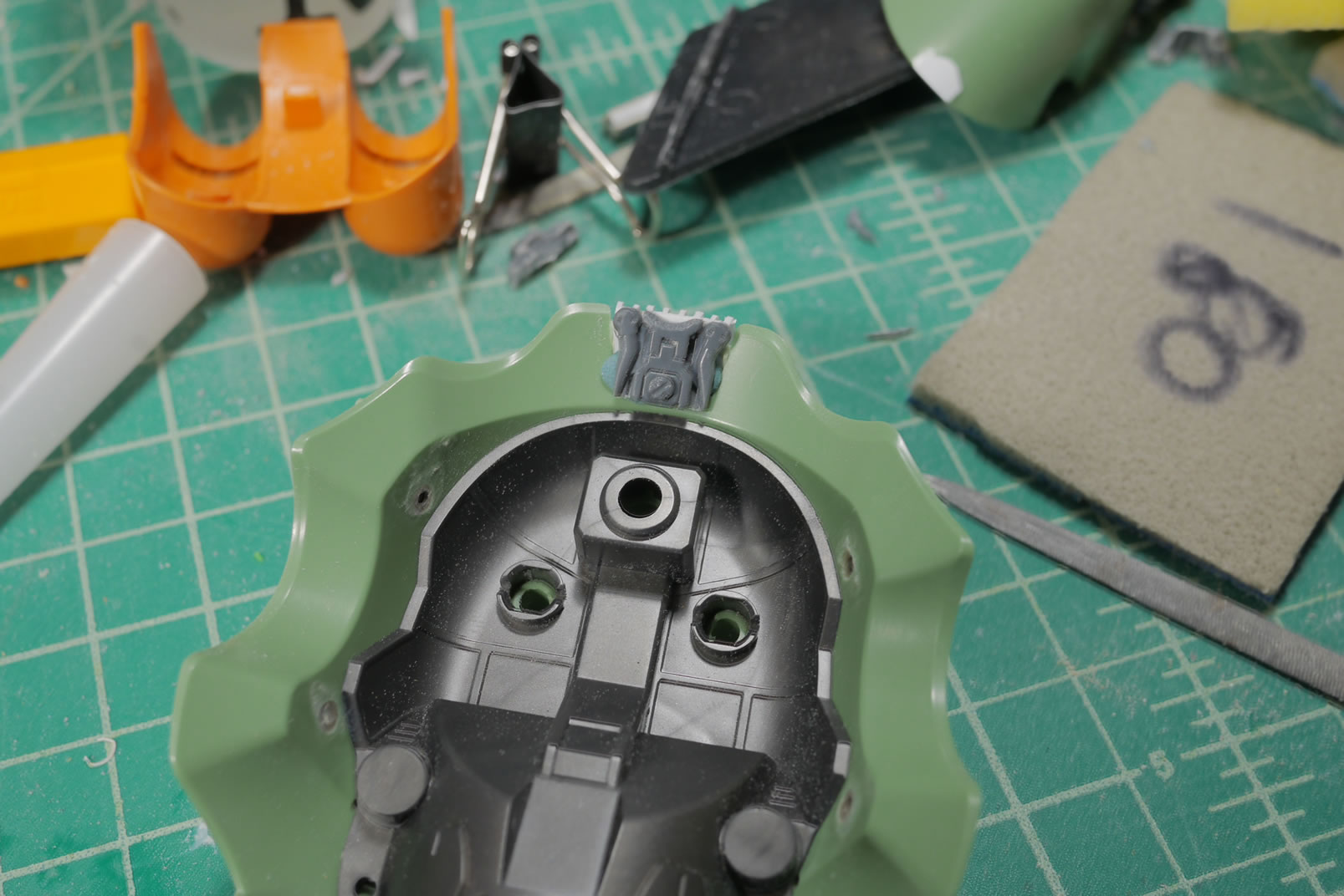
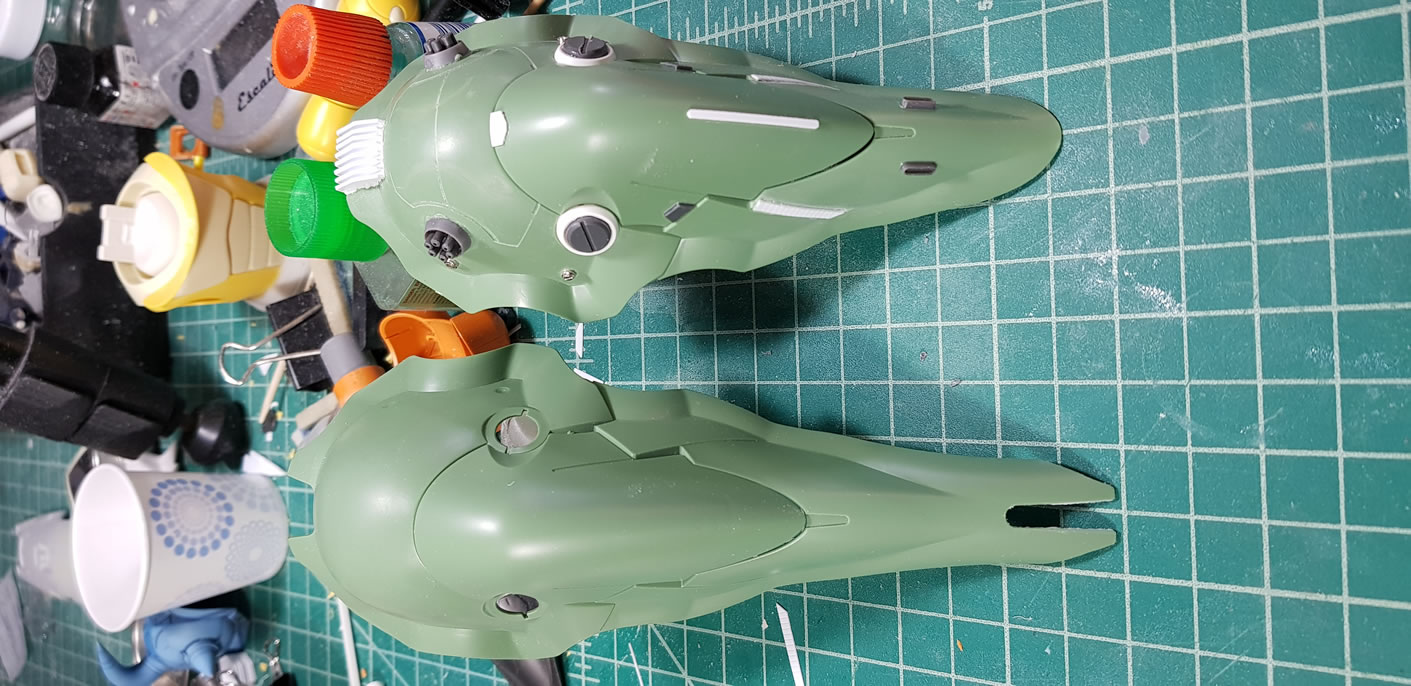
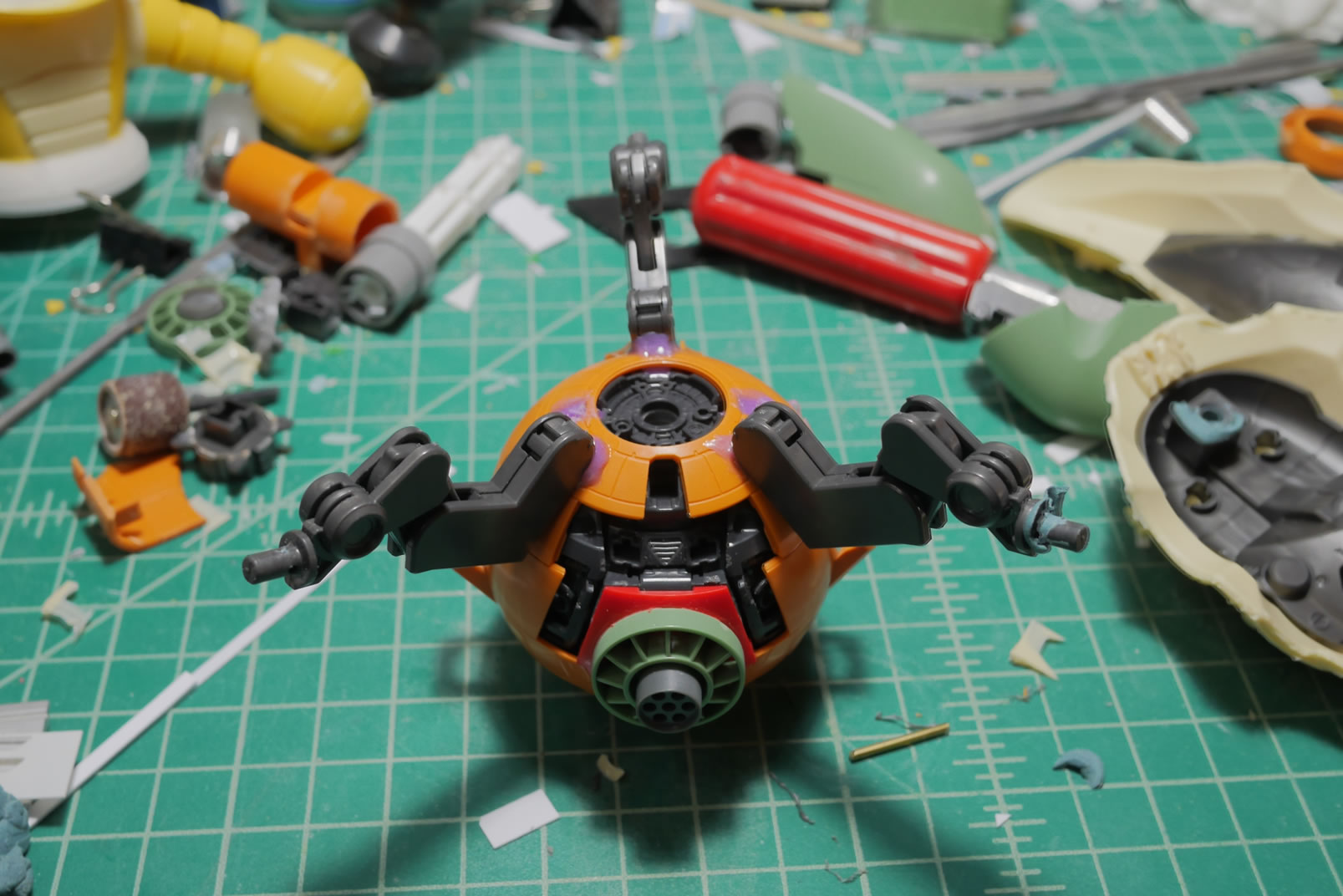
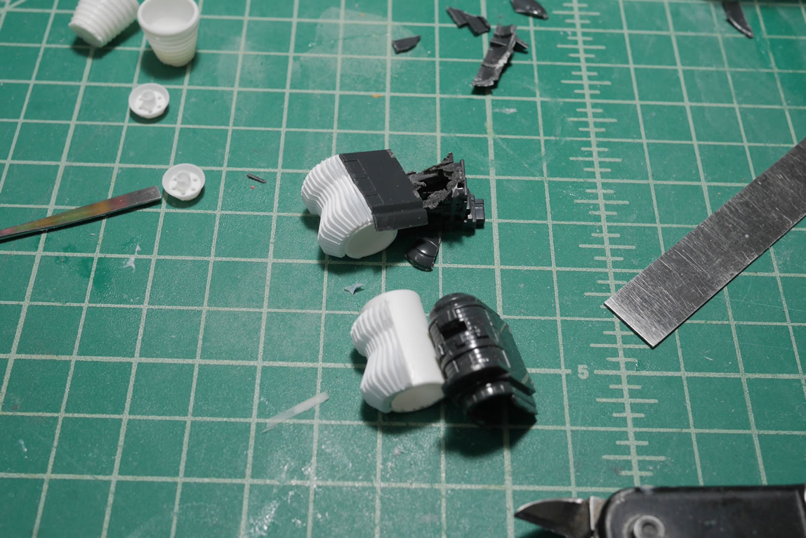
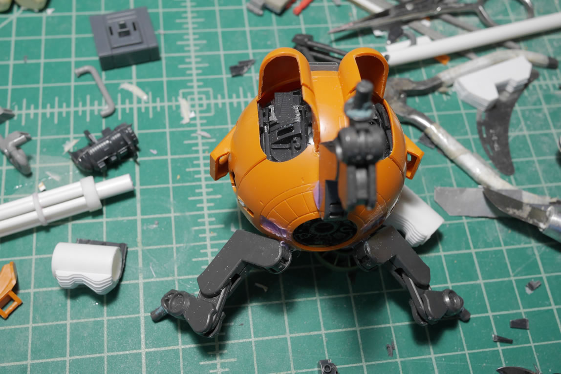
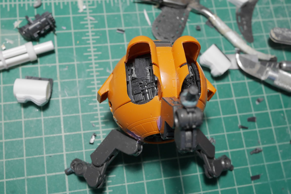
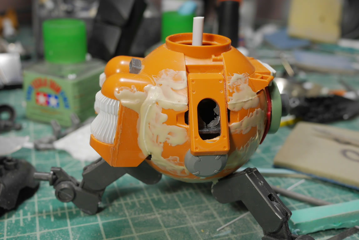
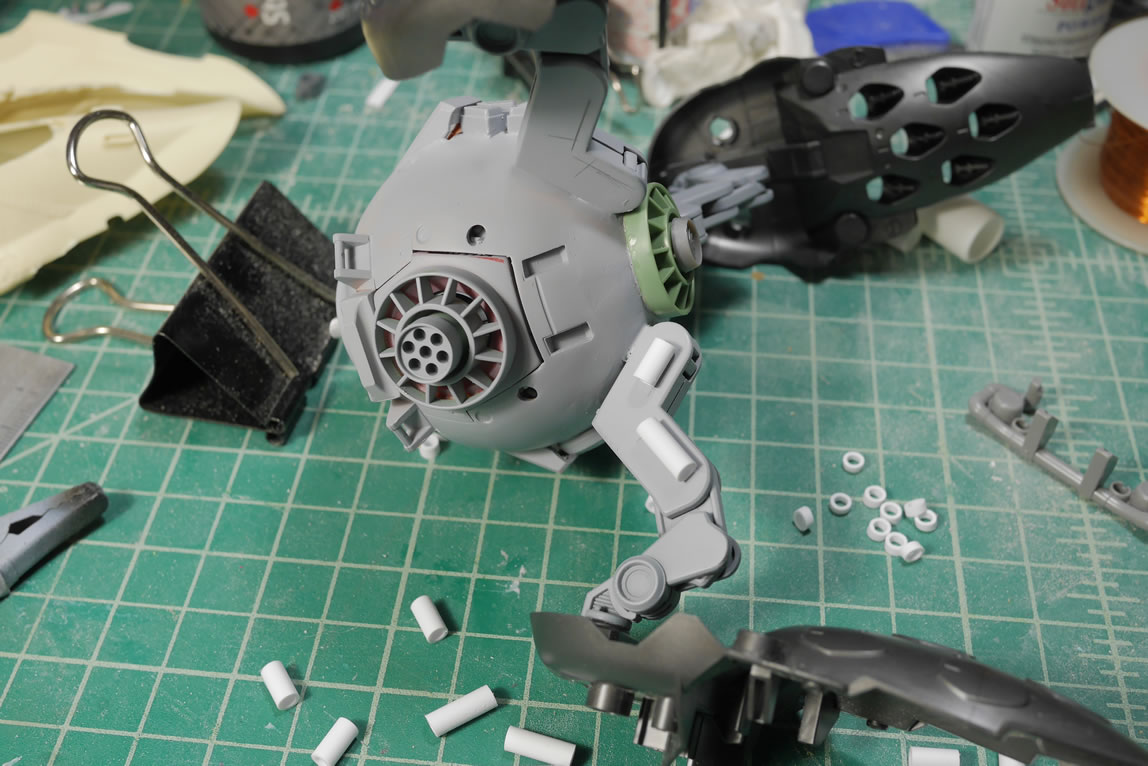
The first step is any kitbash project after the initial test fits is the destruction. Dremels, cutters, hobby knives and flying plastic everywhere is a really fun way to start a project. The torso of the BG is cut apart so that I have an area to combine with the Ball. The upper area is cleared so I can reconstruct the internal areas to create the beginnings of a cockpit. Some plastic plate is added to the bottom and new polycap joints are added to the left side torso and the bottom of the torso for new connection joints for the Guntank arm and the lower torso Ball.

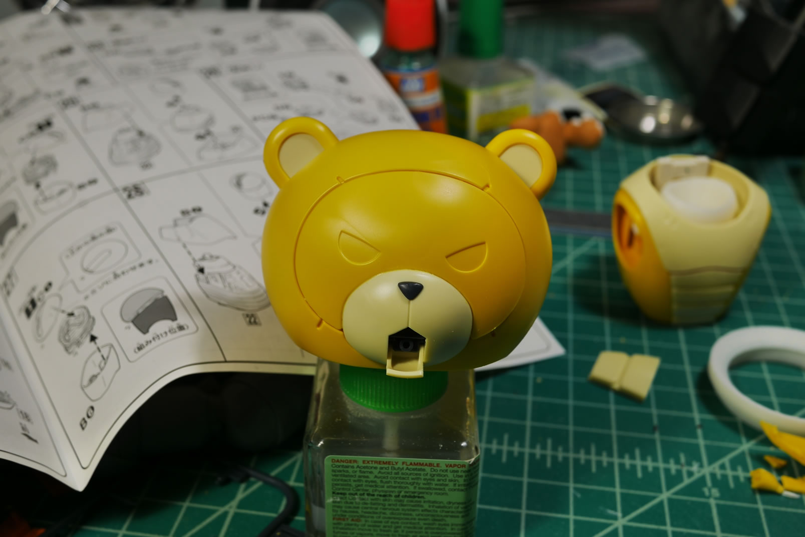
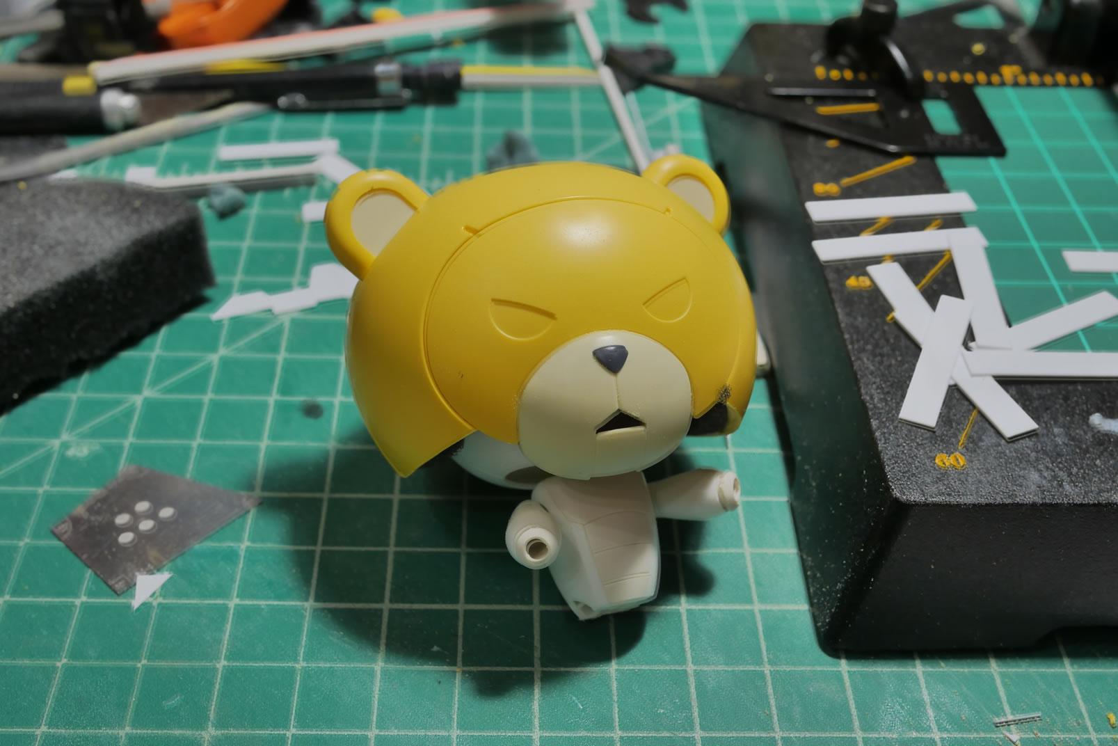
I typically work in a very stream of consciousness method. I have a rough plan or idea, but as I progress, the ideas will change and evolve as the project unfolds. Once such idea that quickly jumped into the forefront is the BG’s head. It seems fairly wasteful to not use the iconic BG head in this project. But how was I going to use this along with the PBG? Heh, I know, I’ll create a motorcycle helmet.
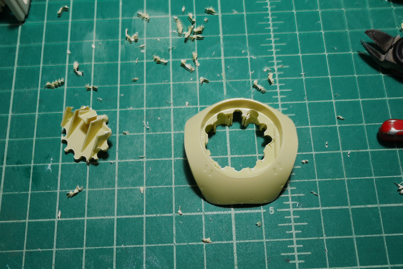
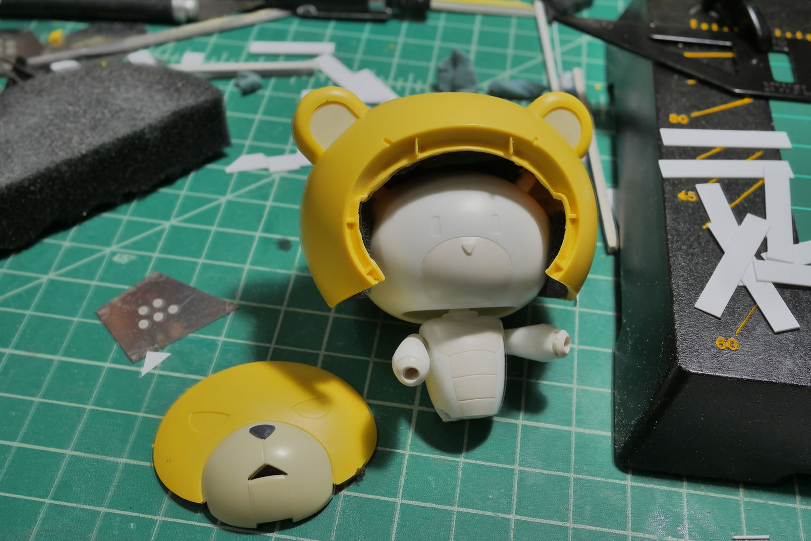
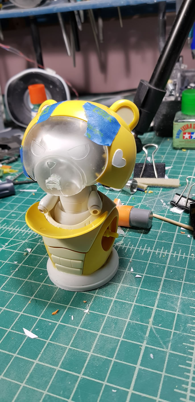
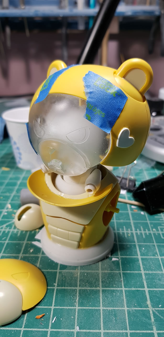
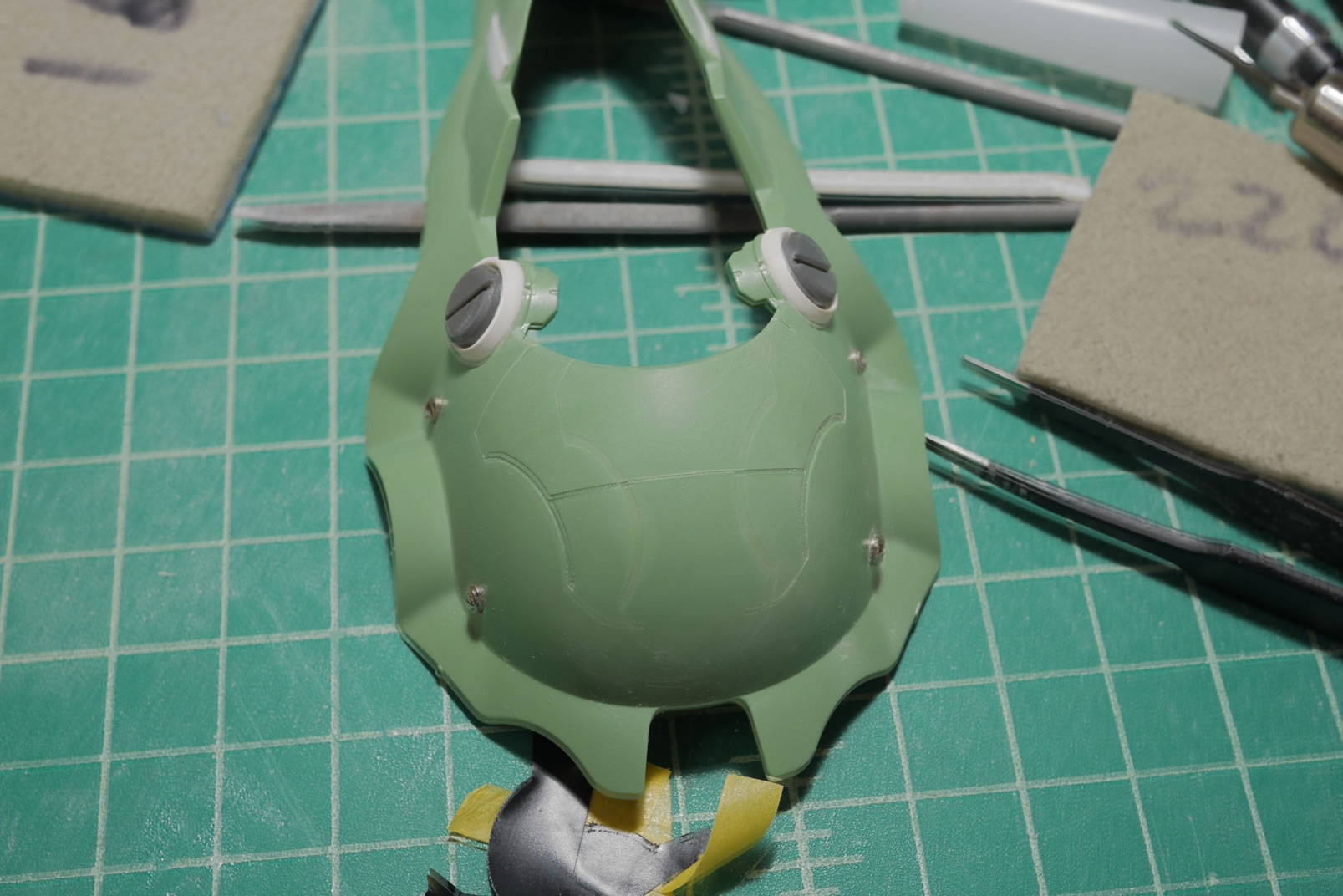
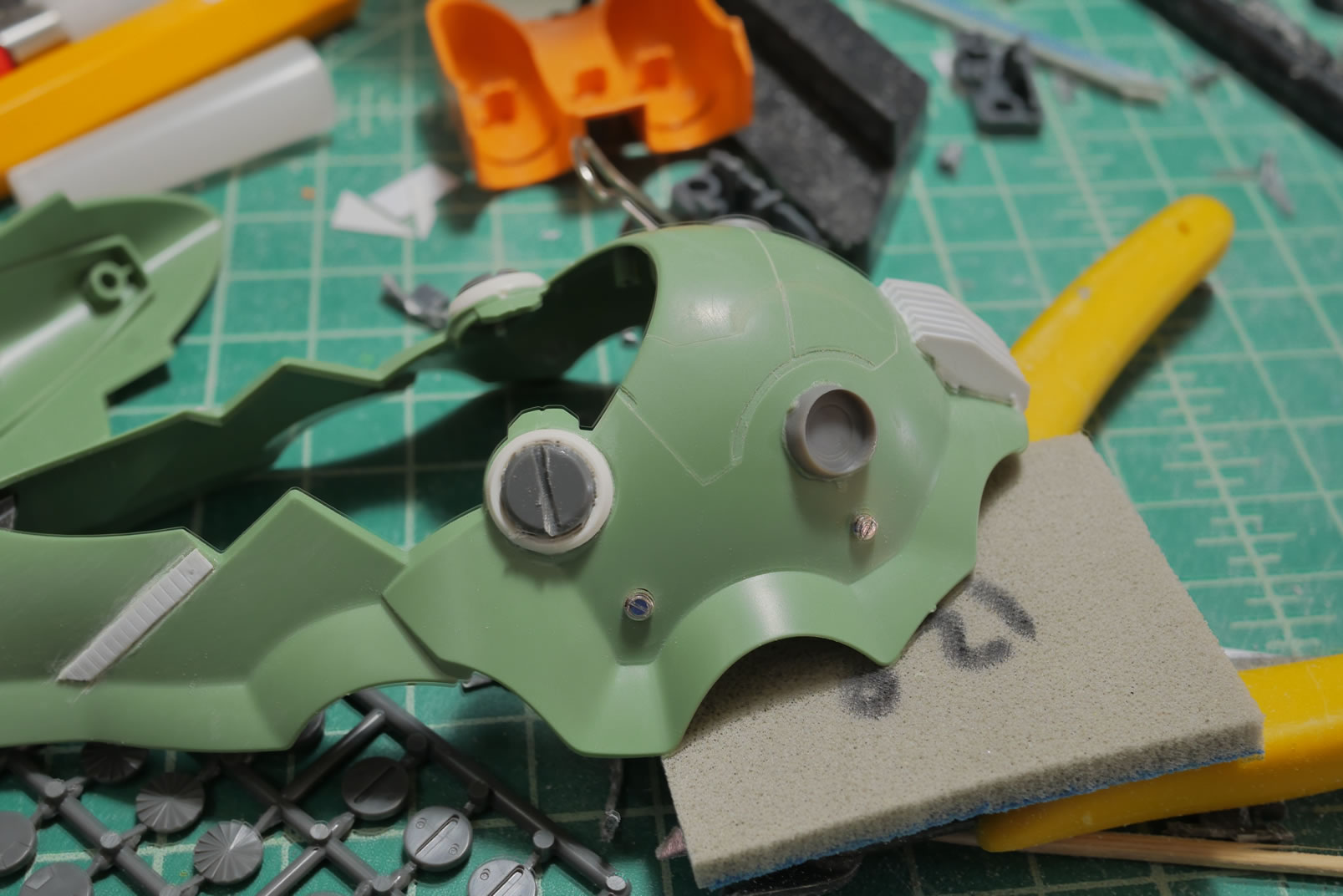
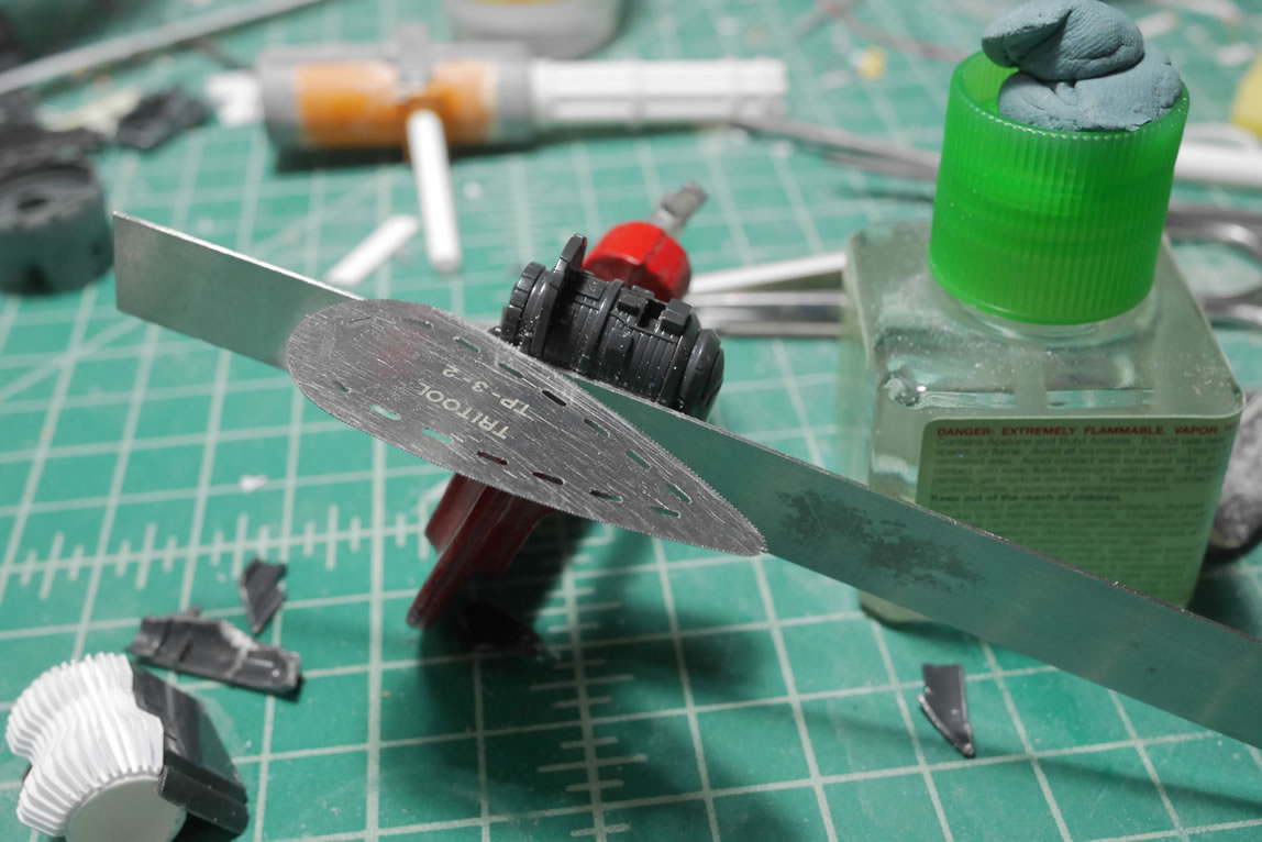
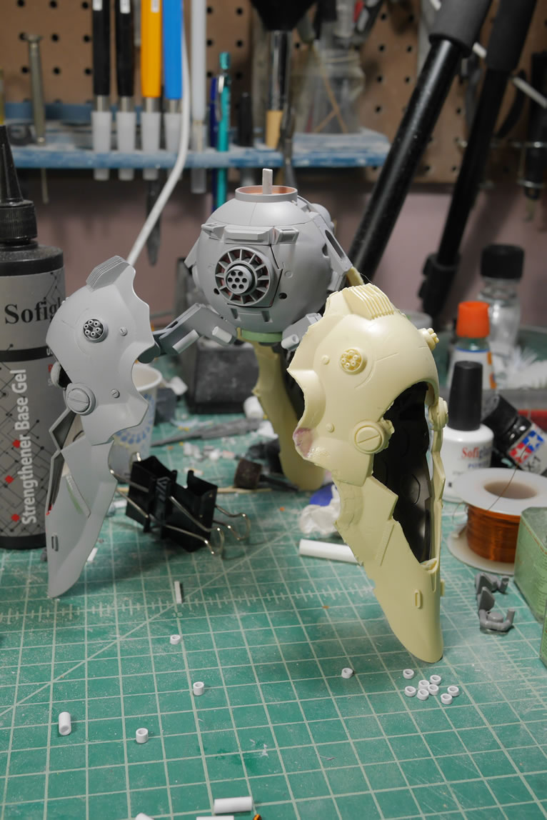
The first step here is to clear out the internal plastic structure to the BG head. The to main halves of the head are cleared and the faceplate is assembled. With everything cleared, I do a quick test fit over the PBG’s head to ensure not just a good fit; but that it actually fits over the PB’s head.
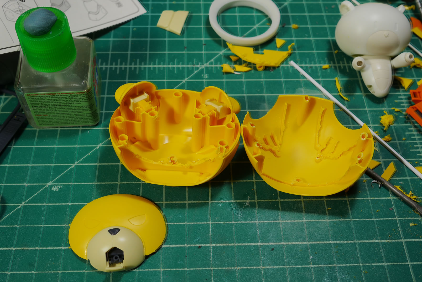
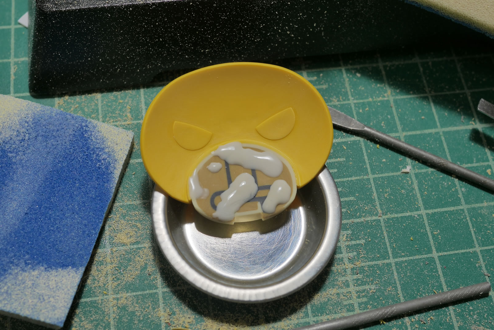
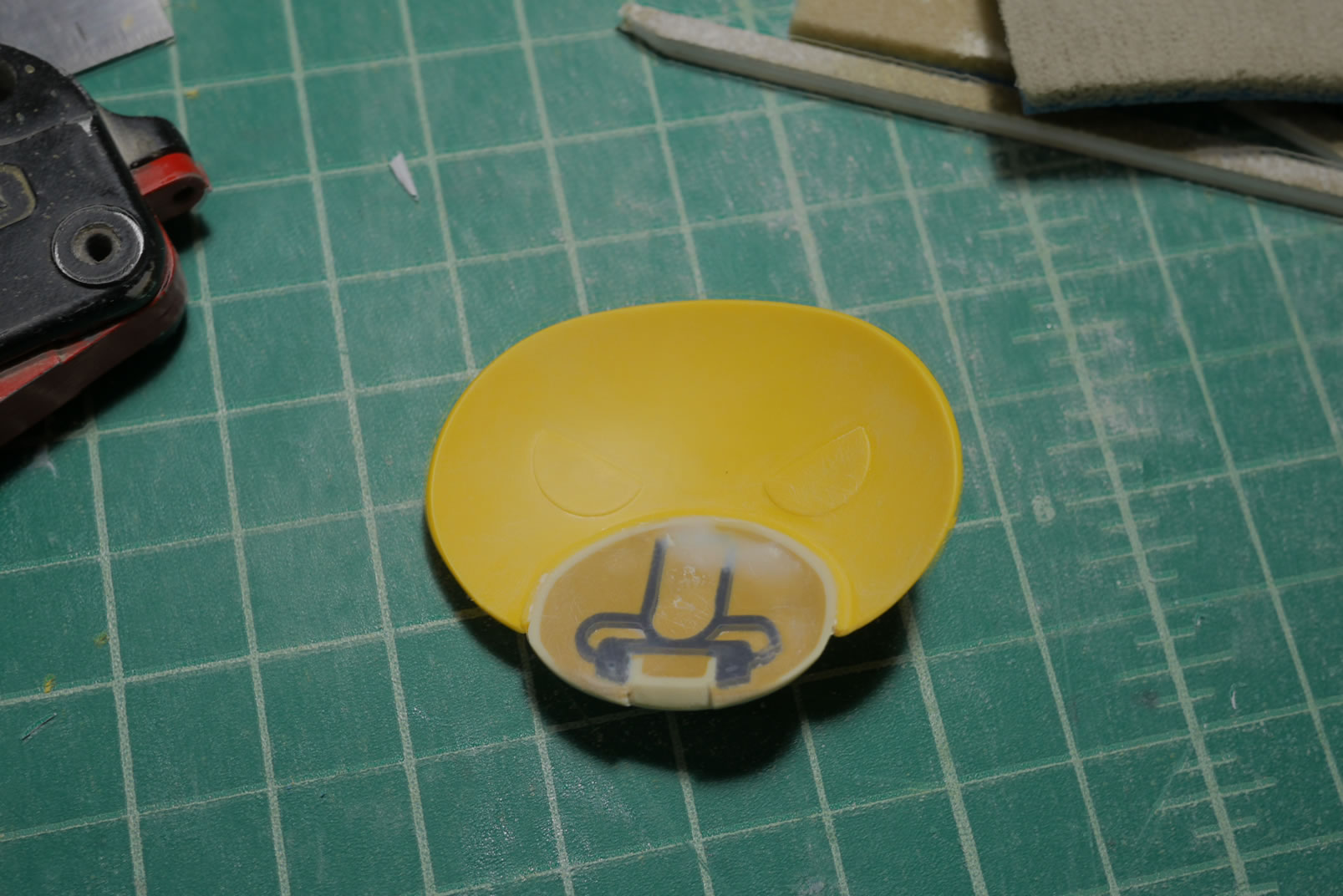
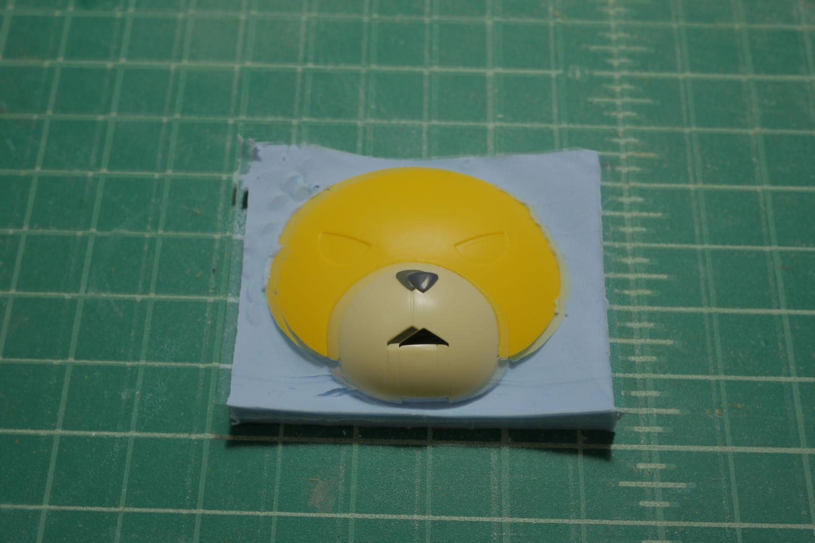
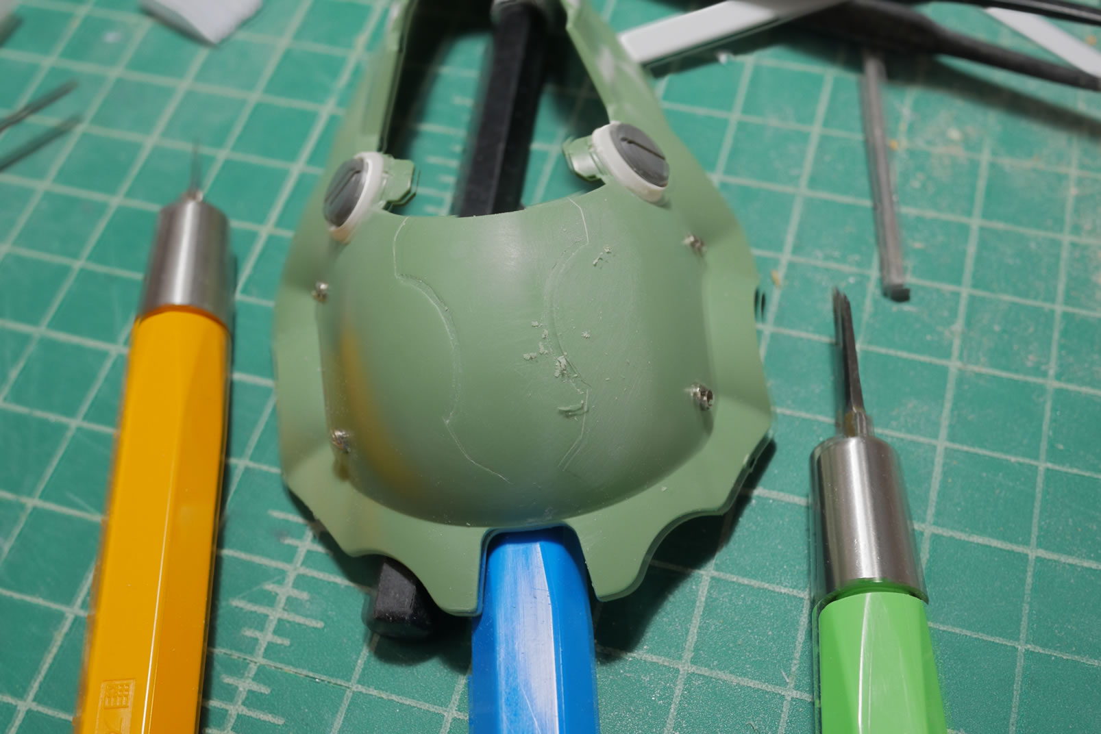
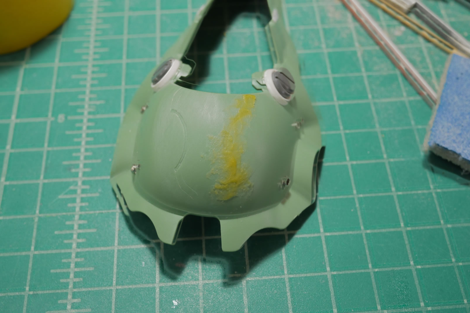
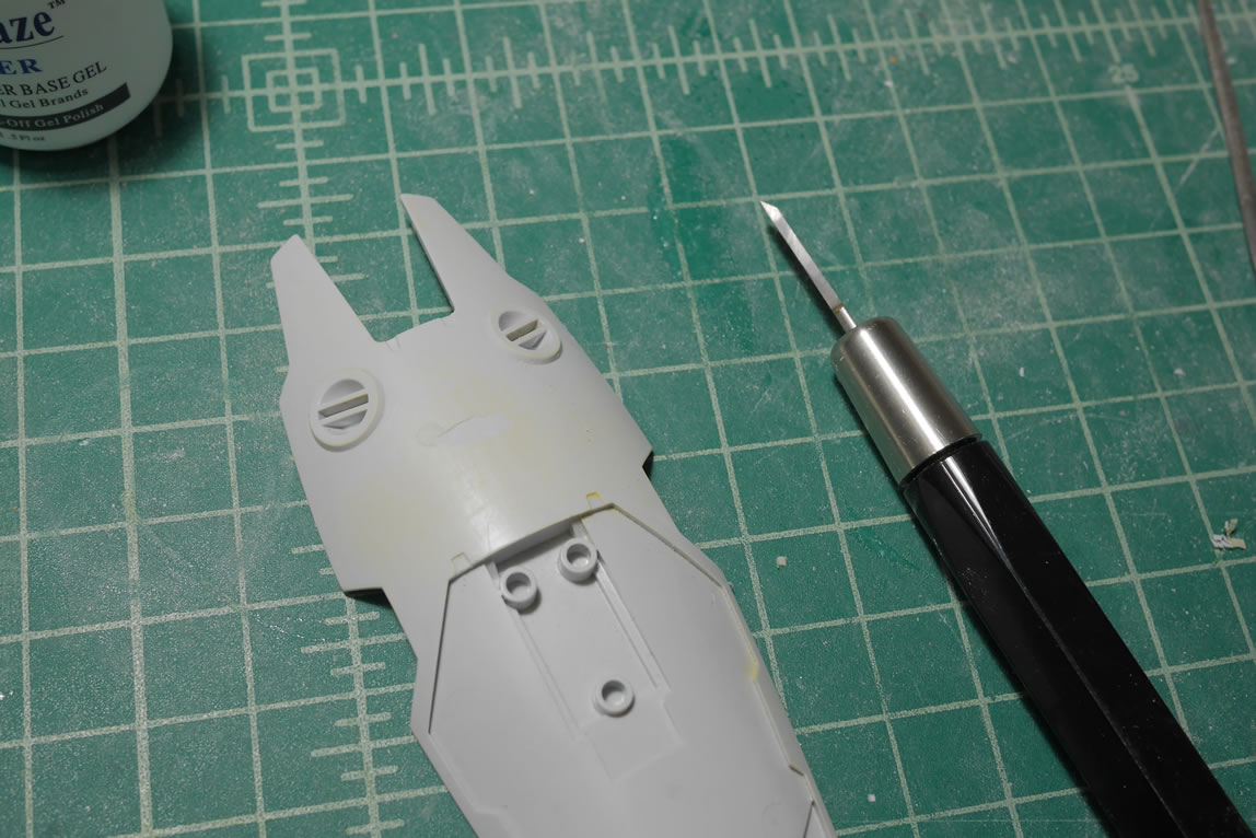
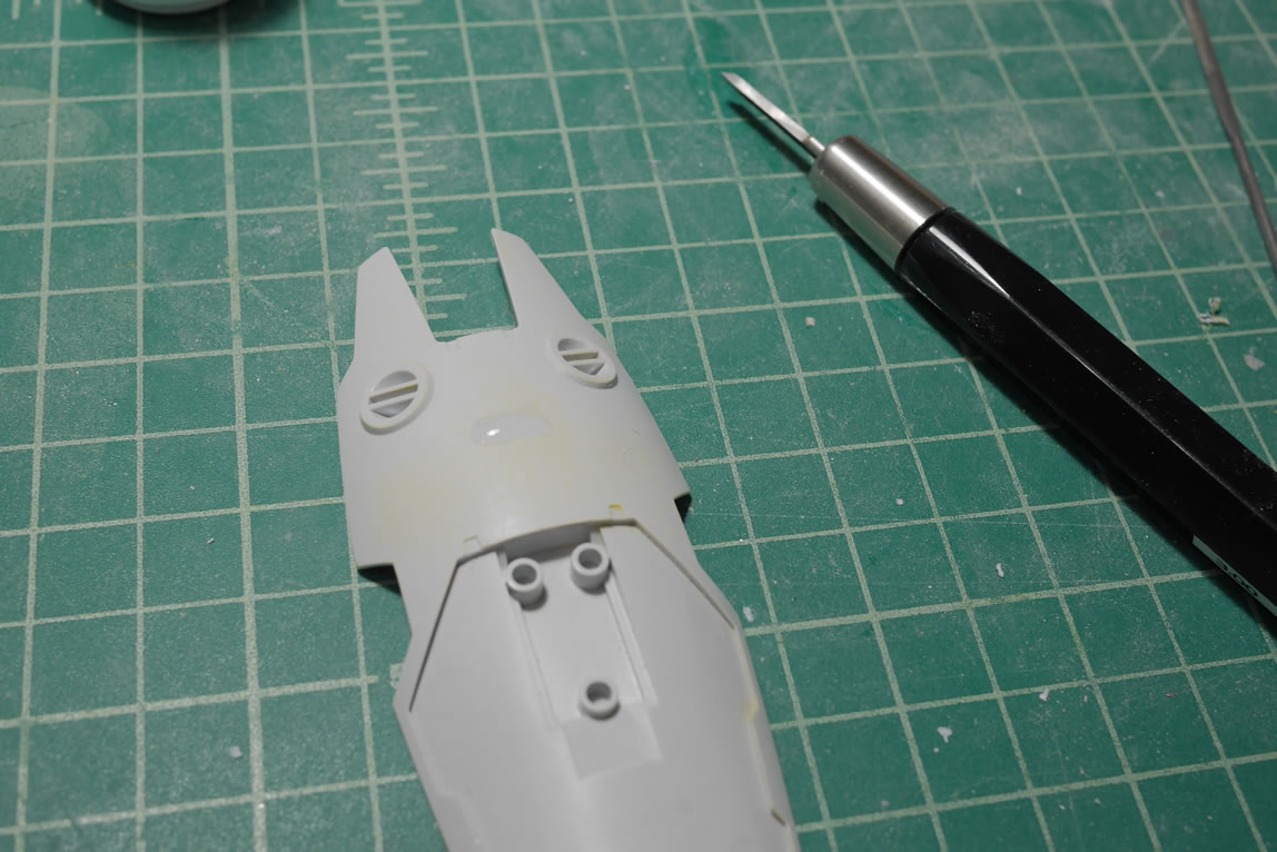
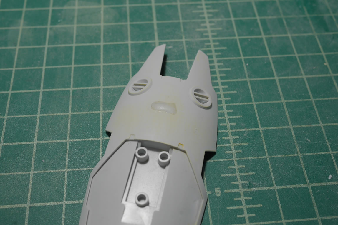
The main two bits of the head are good to go, so it’s time to focus on the face. The idea is that I will make a mold of the face and make a clear resin copy of the face. This will act as the helmet’s clear face piece. For this to work, I needed to glue the face pieces together and putty the hell out of the back side of the face since there are plastic structures that attach the face to the original head areas. Now, the structures in the main headpiece are gone now, there is no need for these. And once I make a clear copy, I don’t want to have these structures in the resin either as it would just look out of place. This whole area is puttied and sanded down.
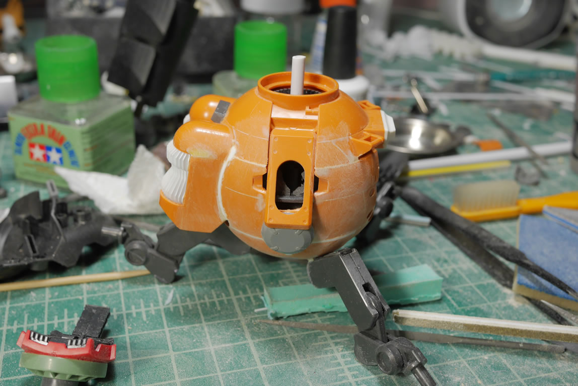
Small pockets of bubbles and surface defects need to be fixed, so dissolved putty is used. While all these putties are curing, I’m working on other areas of the project; but for the sake of continuity and ease of following the project progression; I’m grouping the focus areas in this post. Another few quick test fits to make sure the putty isn’t blocking anything with the PBG head inserted.
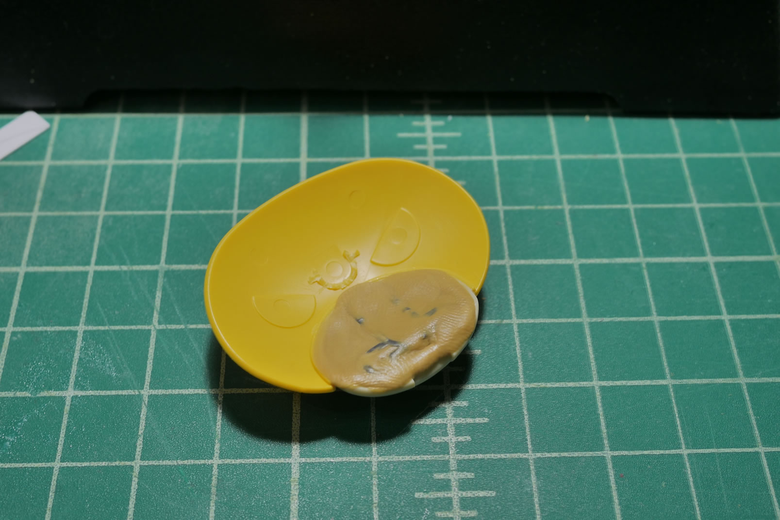
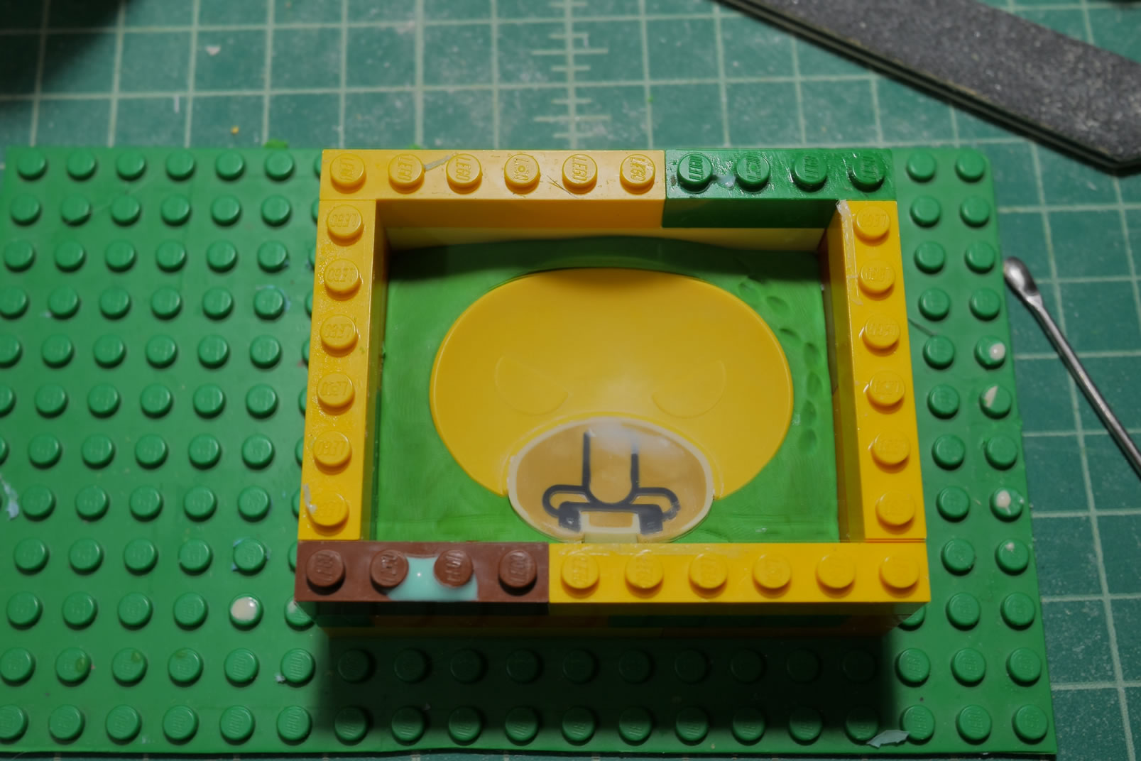
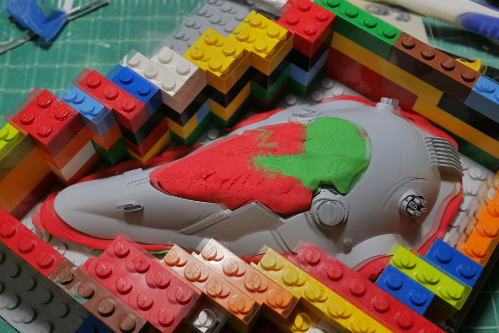
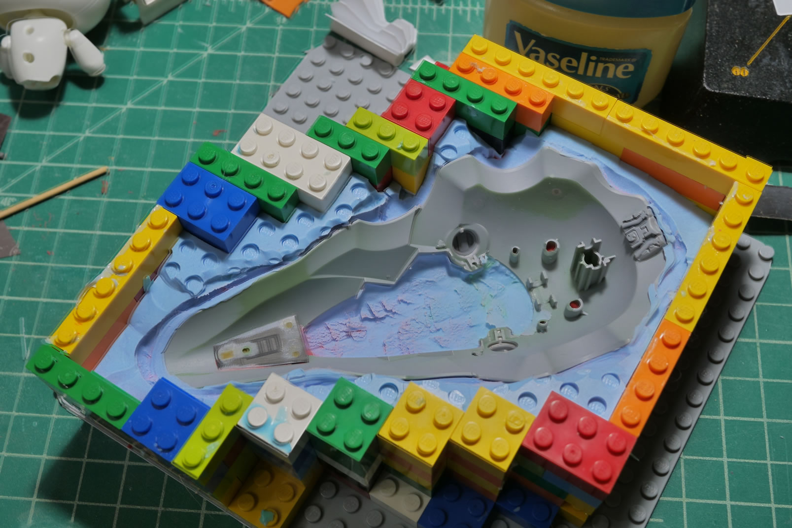
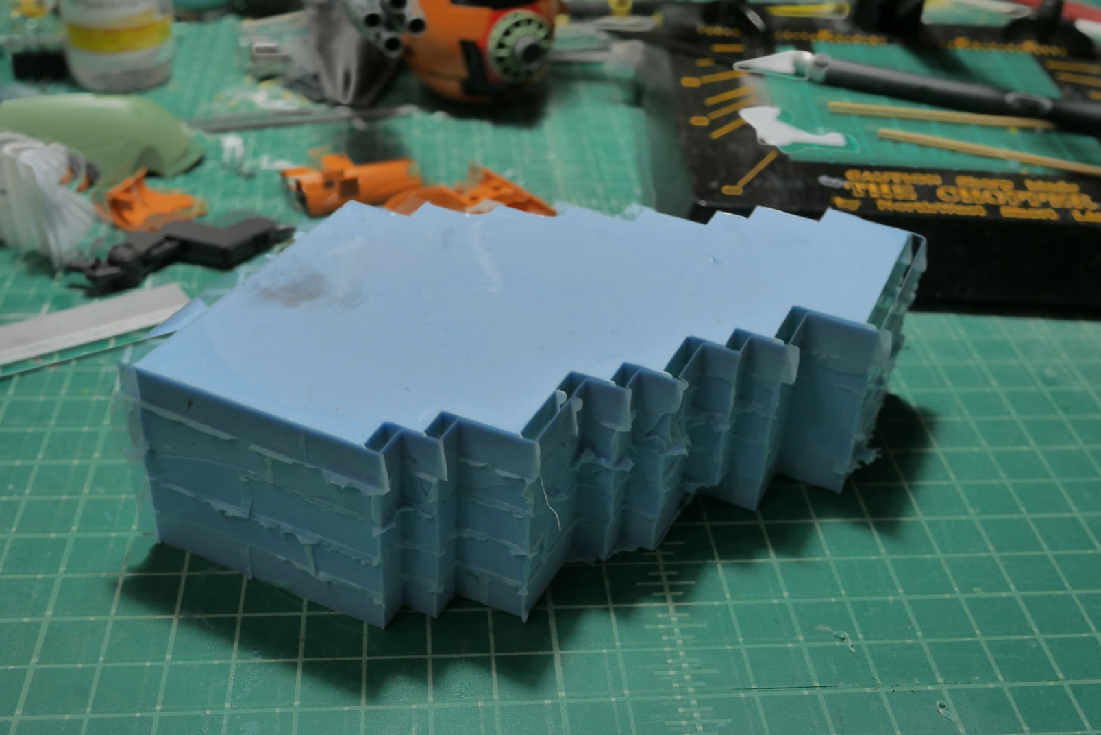
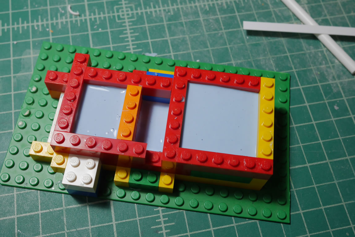
With the surface sanded and ready for paint. I don’t actually go to paint since I can eyeball the look and just go right into making the mold. A bounding box of legos is built and the bottom layer is filled with playdough. The face side is pushed into the playdough and the first half of the mold is made with silicone RTV. Once cured, the box is broken down and the playdough washed off and it is ready for the second half of the mold.
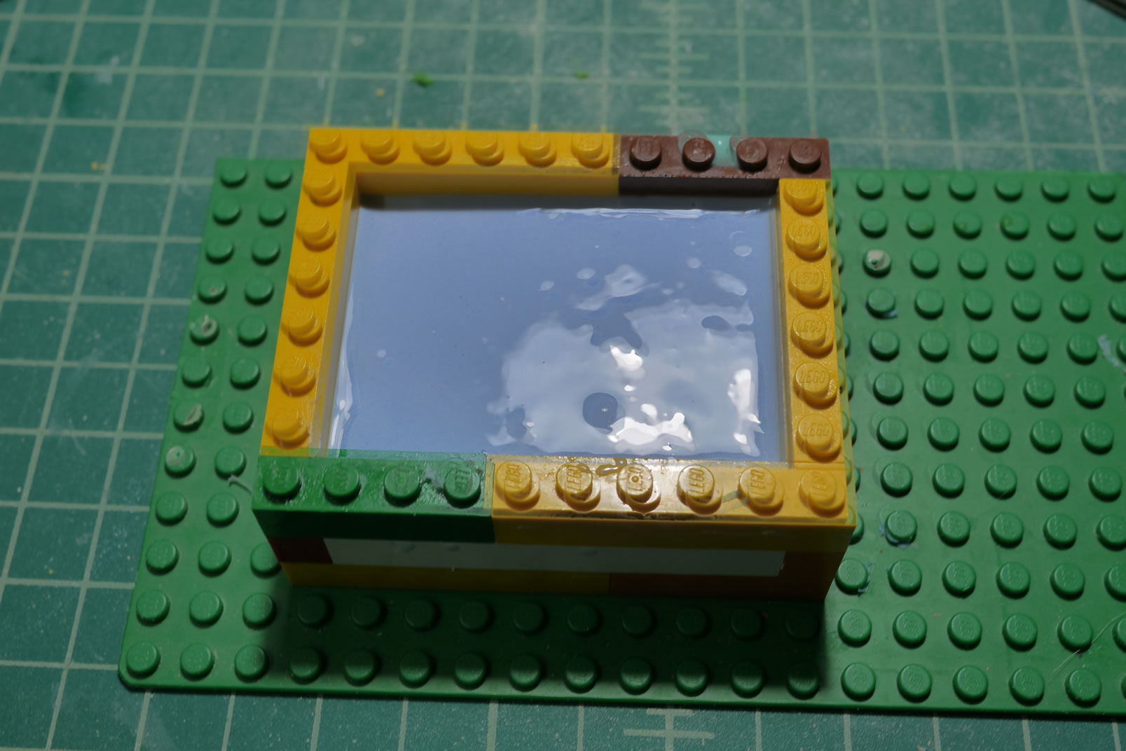
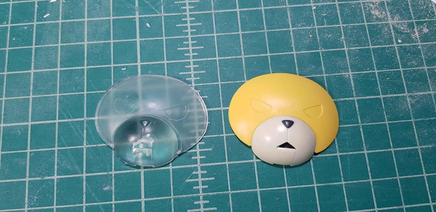
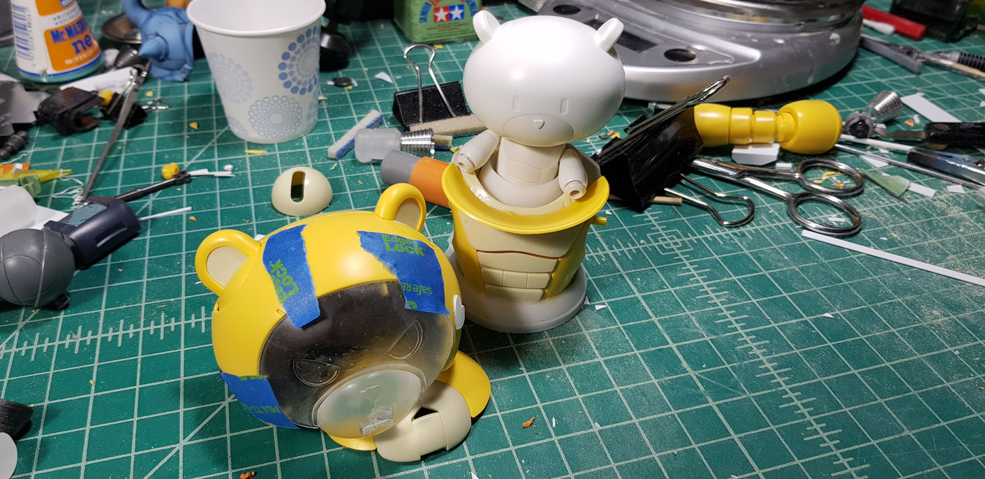
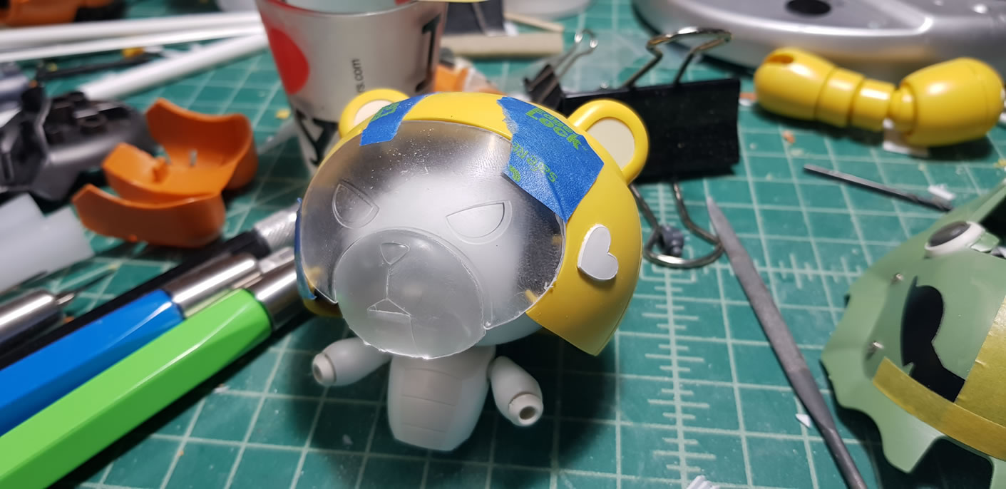
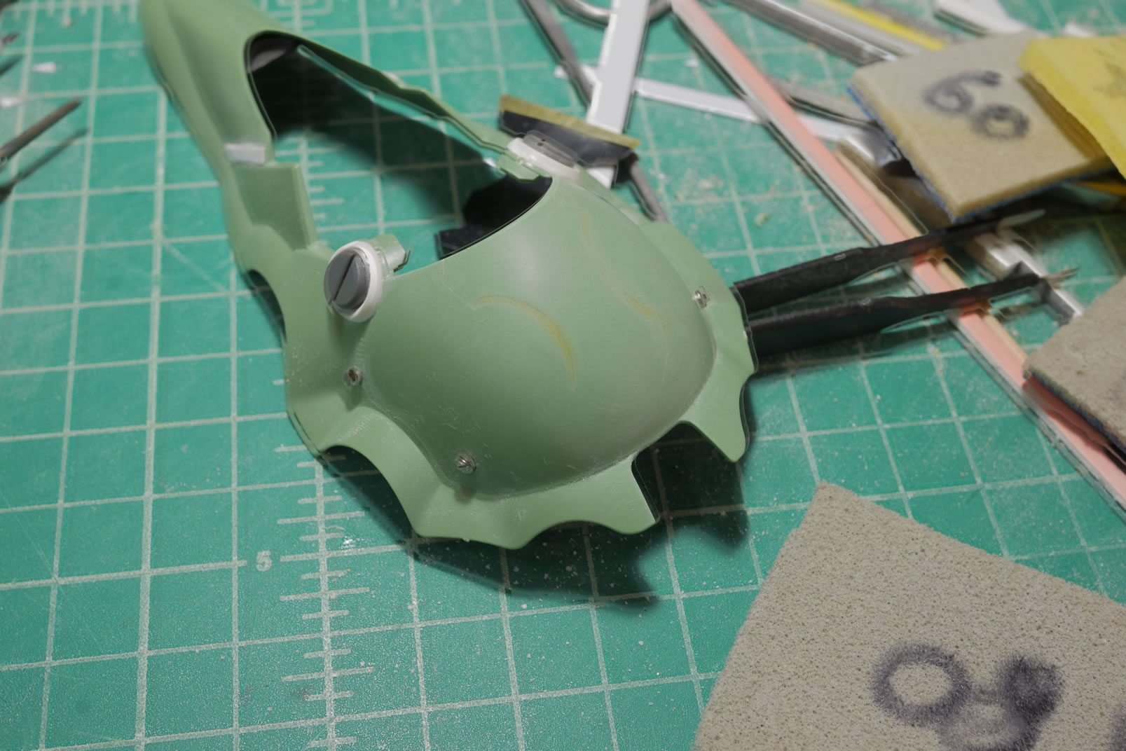
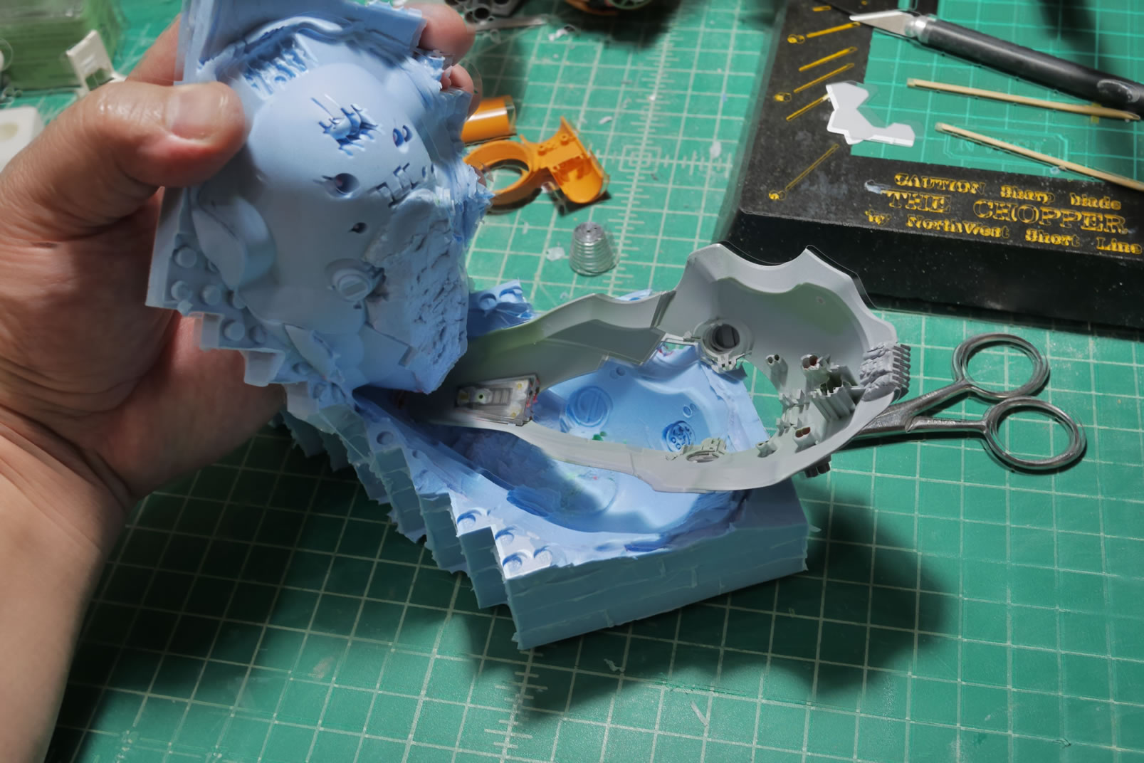
Once the two halves of the mold are made, I can pour clear resin and stat making clear face molds. Once cured, I get a quick test fit and start to see how this will come together.
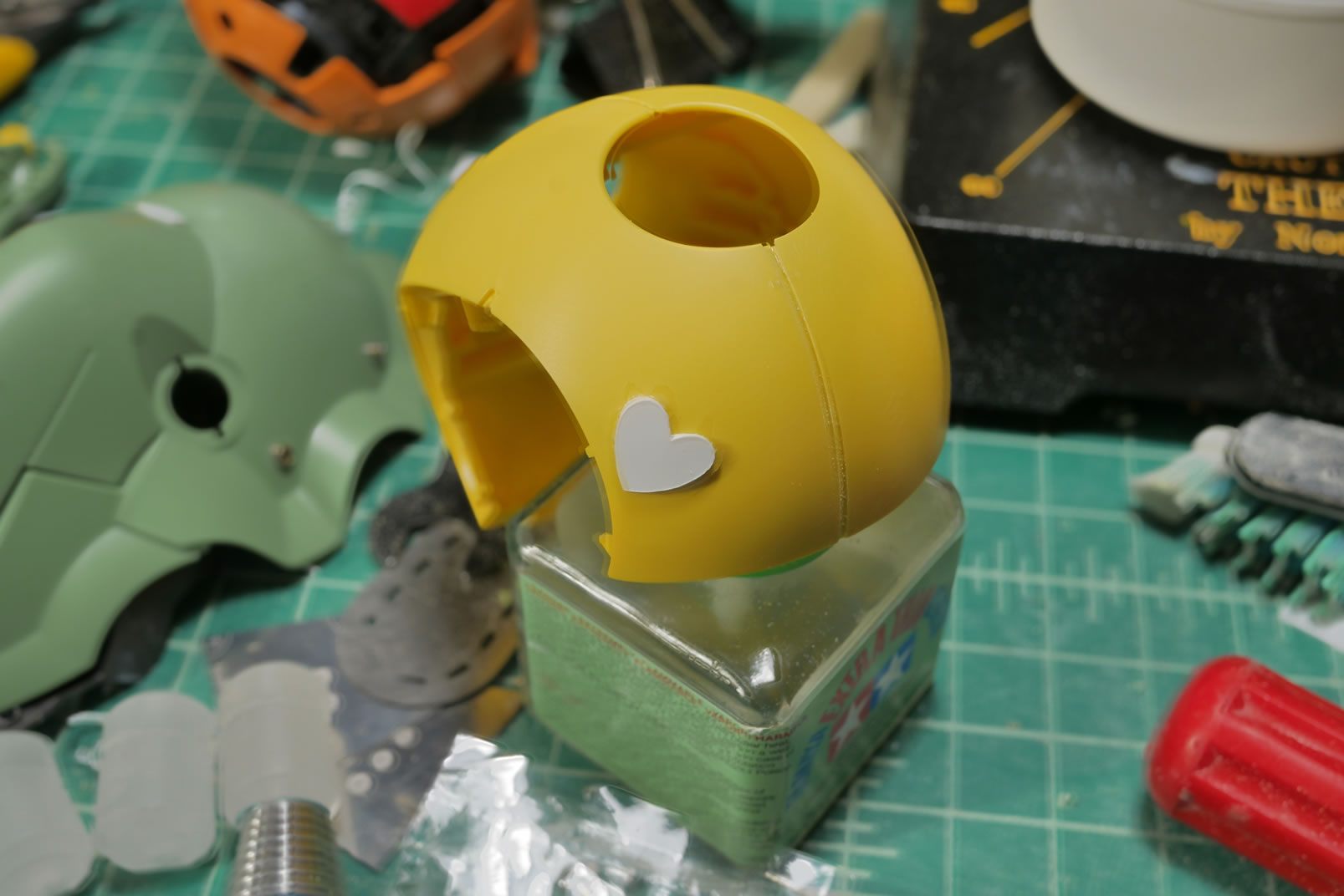
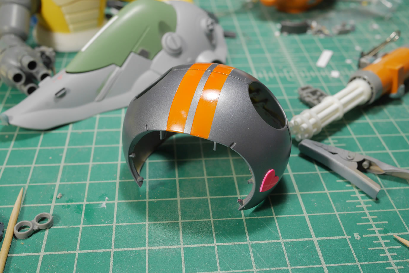
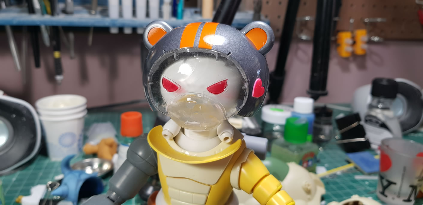
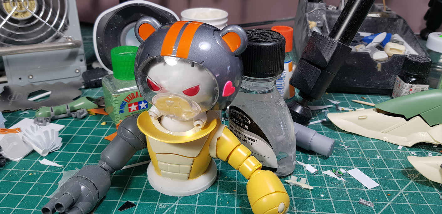
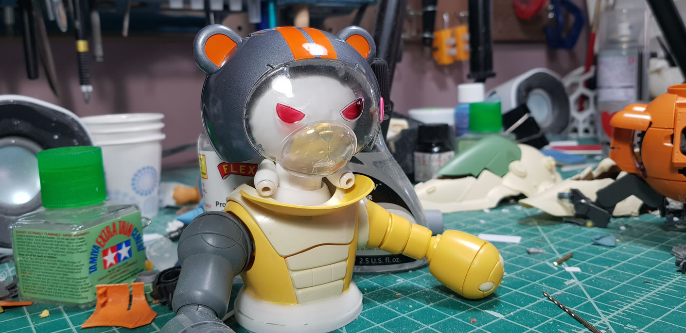
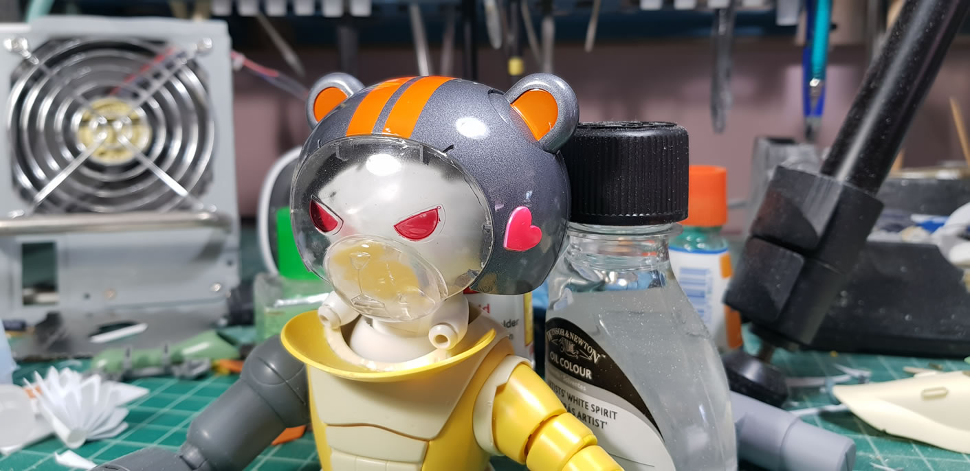
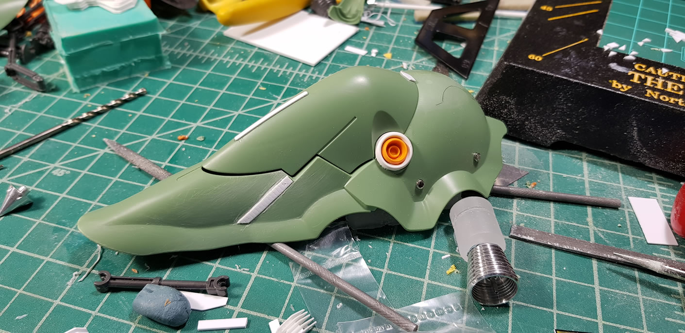
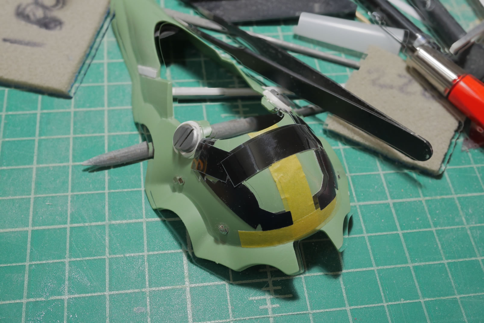
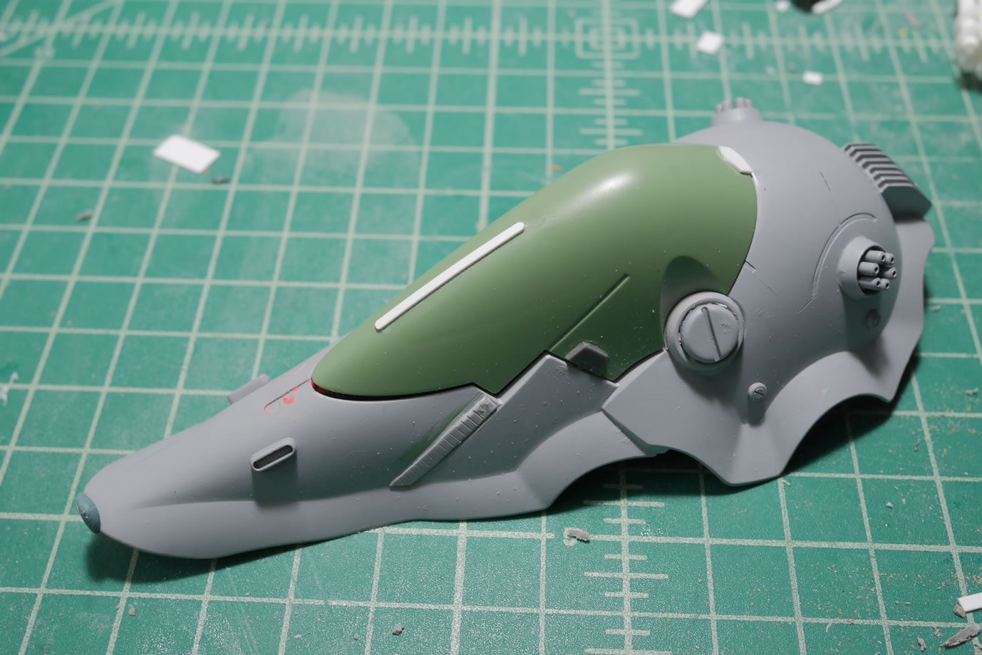
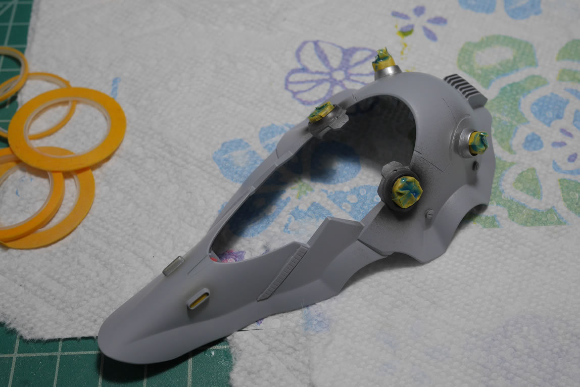
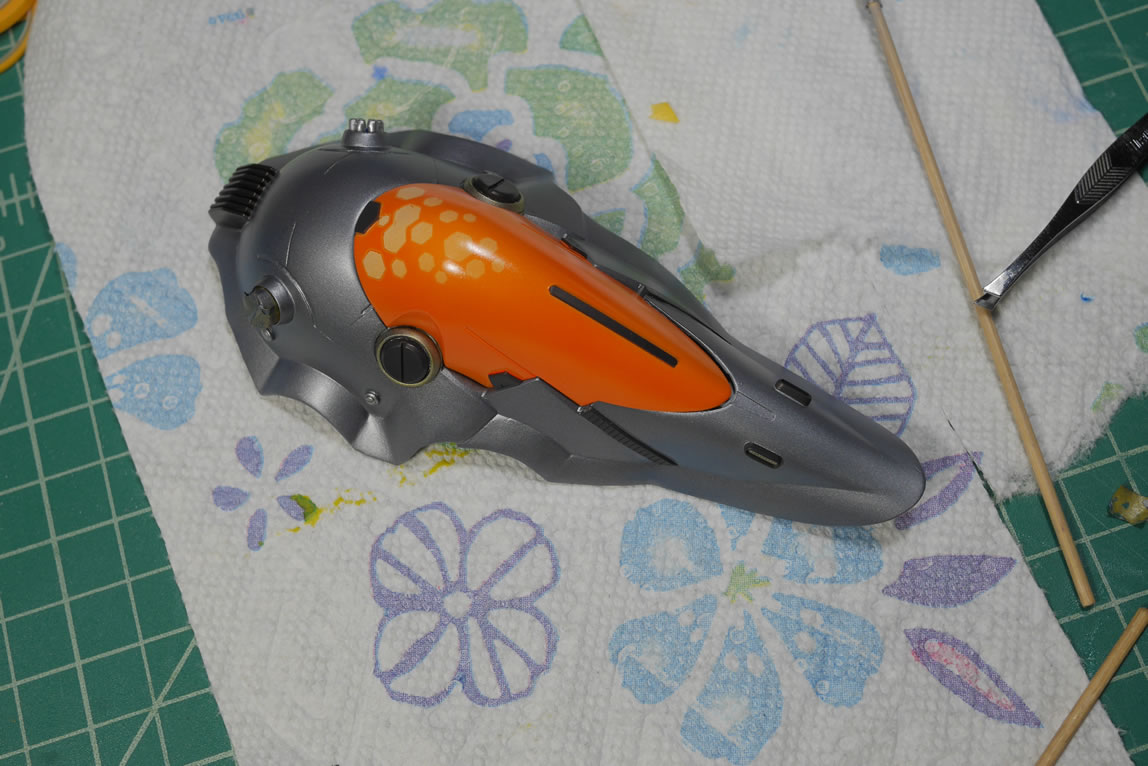
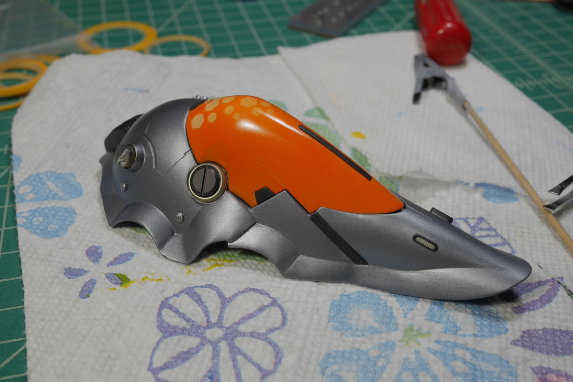
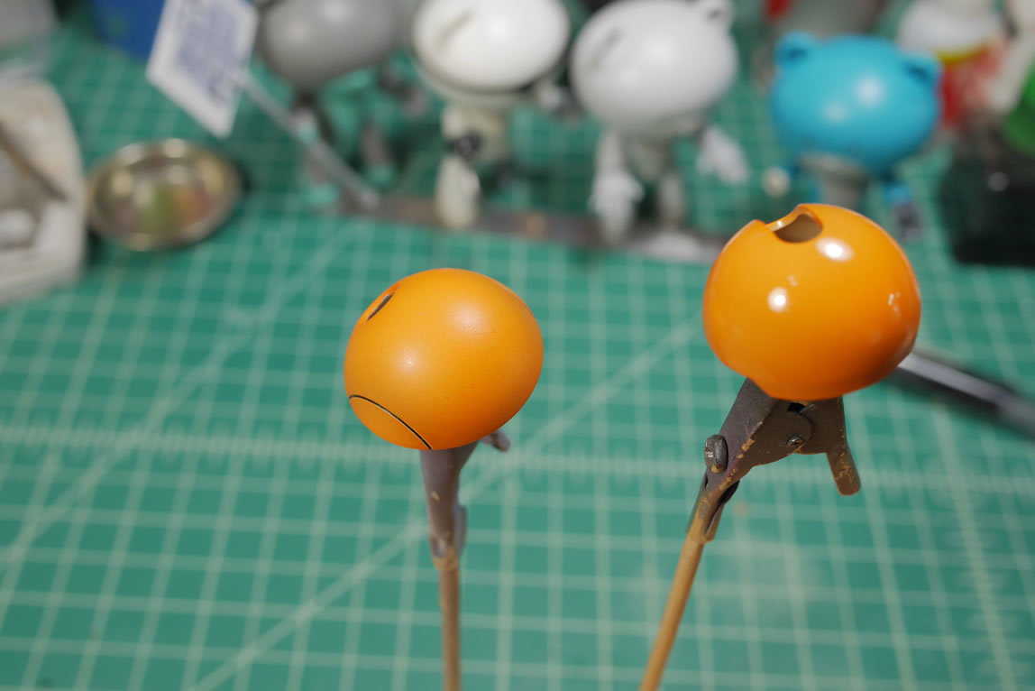
A few more test fits and some surface prep for the main head piece get it ready for paint. I added a little heart plastic detail that I will go into more depth on how that was created later in this post. The little heart detail is a nod to our BearGuy shirt design. Again, I’m working on several areas of the project at the same time while other areas are curing. The head piece is primed to check for surface defects and then everything is painted.
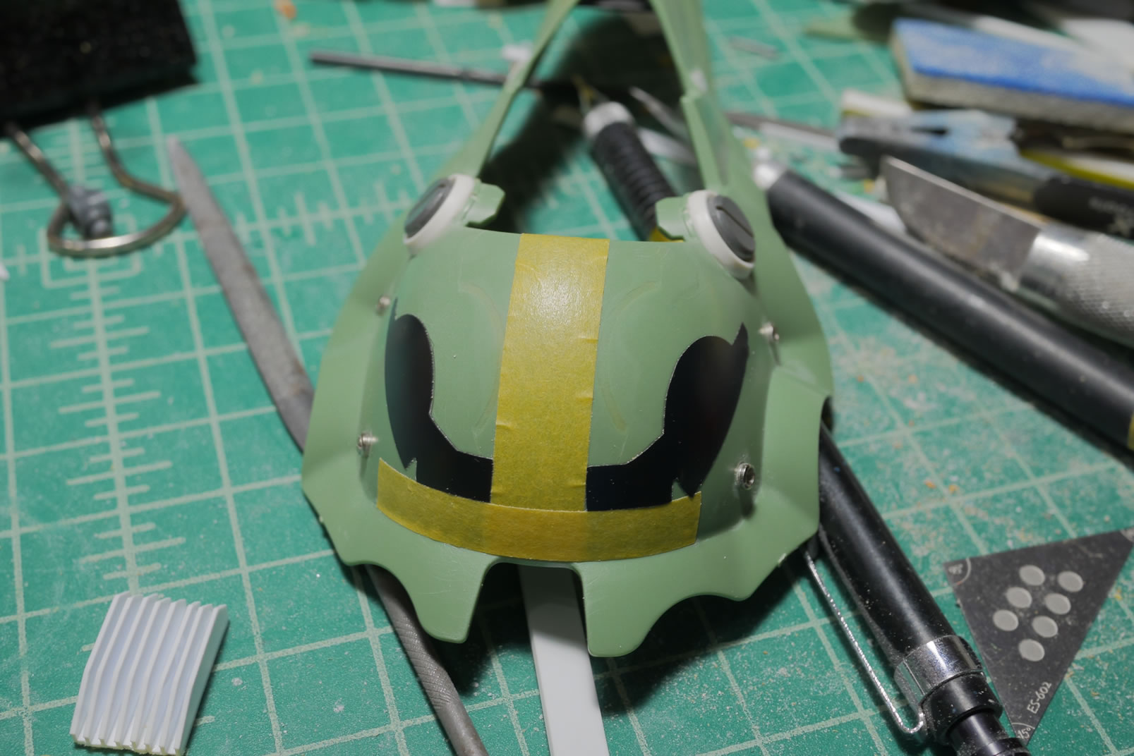
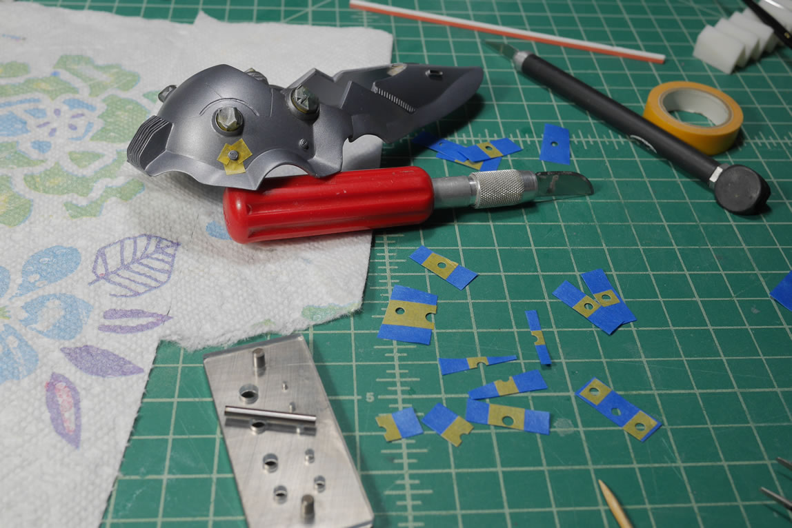
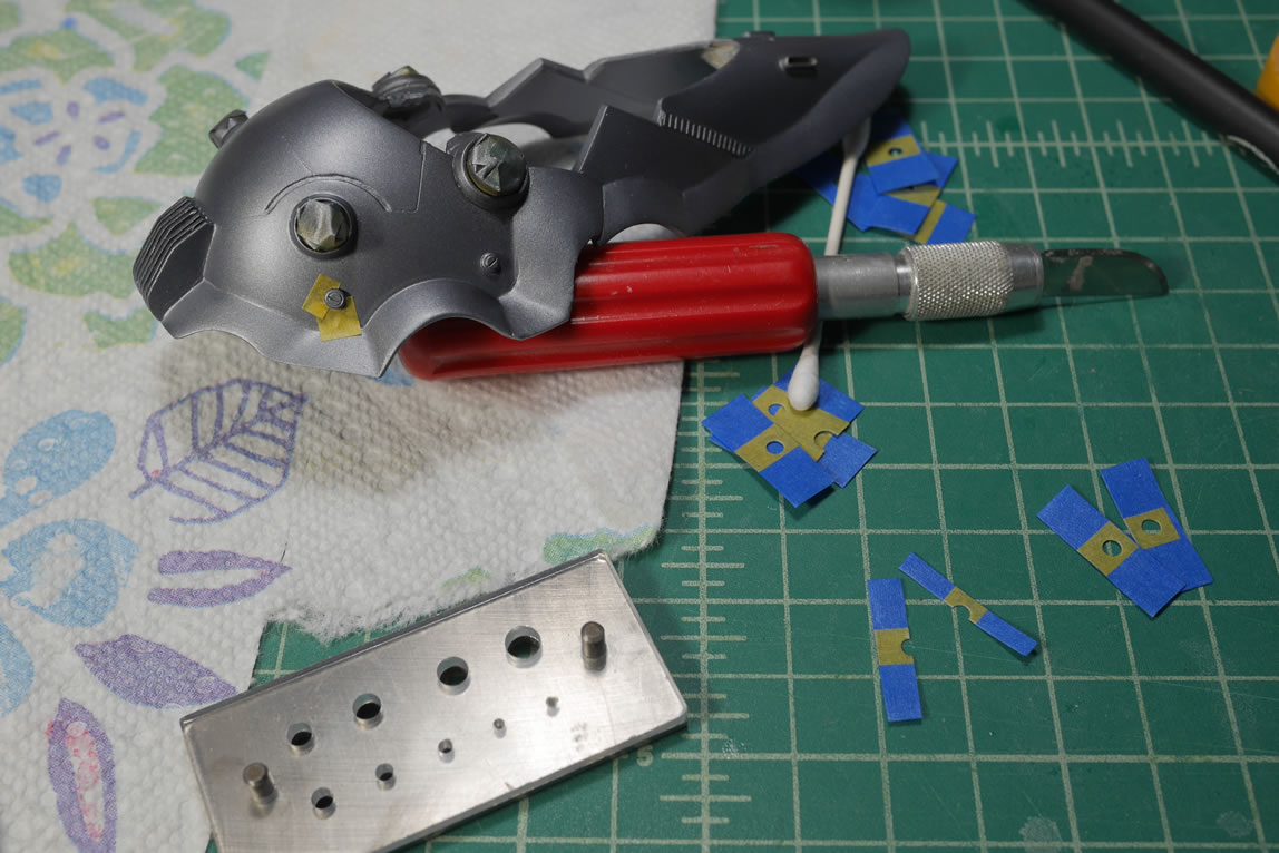
The main helmet is painted with Tamiya TS-100 which I used for my Mercedes build. I masked and painted an orange stripe as well as masked and painted the heart with Finisher’s lumi-pink.
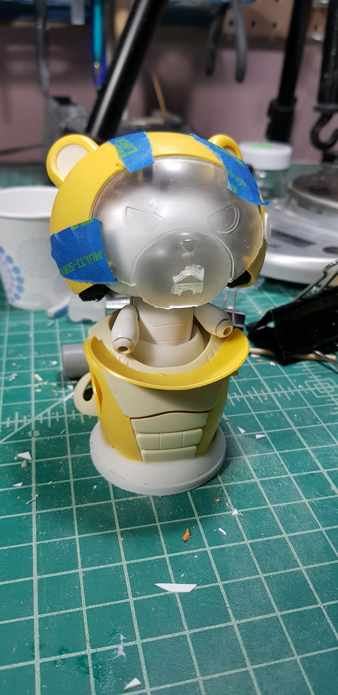
The eyes of the face are painted with clear red. The back side of the face is painted with clear gloss. Then the whole head is assembled with the face piece glued to the main head using aircraft canopy glue. Once everything is set, the whole helmet is sprayed with copious amounts of clear gloss to get that shiny motorcycle helmet look and feel. I have foam inserts glued to the inside of the helmet to provide some cushioning when it is on PBG’s head. It also works to center the helmet over PBG’s head. At least I have something finished in the first progress post for the project.
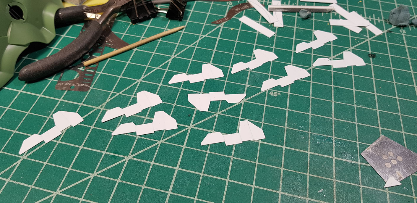
Below is the first attempt at making a shaped heatsink. So this was a complete failure. But it works to illustrate how to do this if you have the patience. Also, while I was working on this, the original plan for where I was going to place the heatsink changed. But the idea here is to use the chopper and cut plastic pieces out and glue them together to create each individual fin of the heatsink.
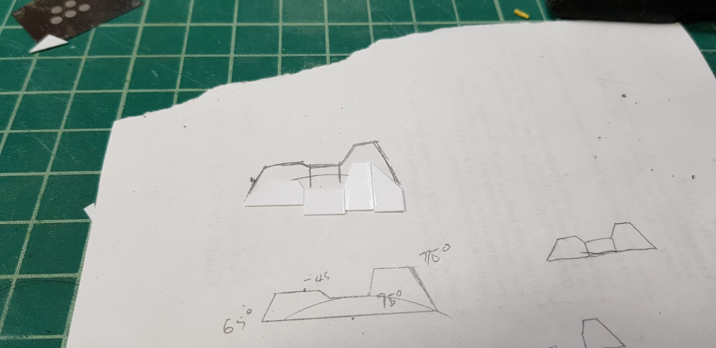
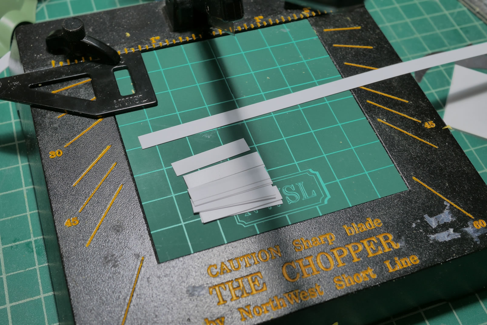
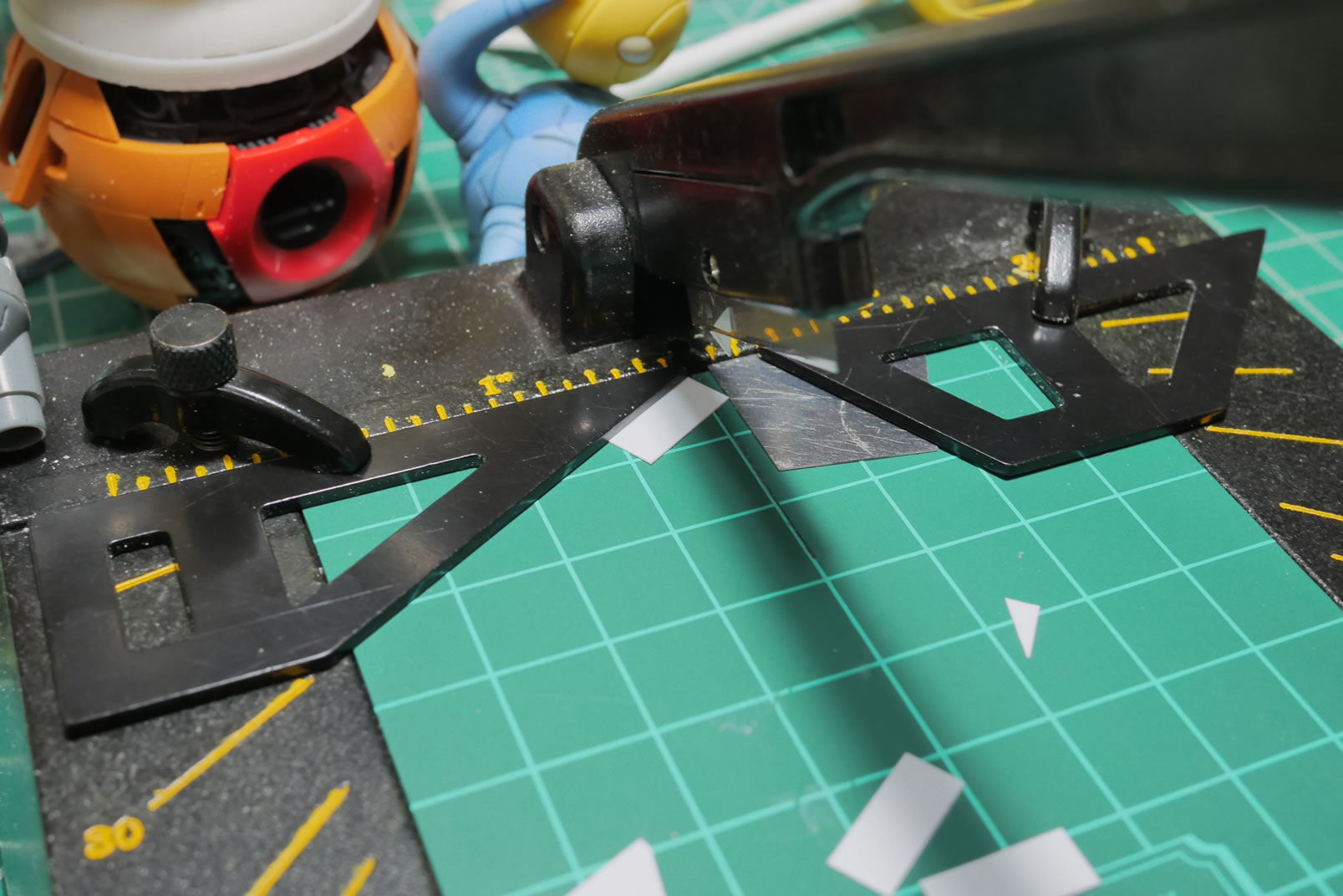
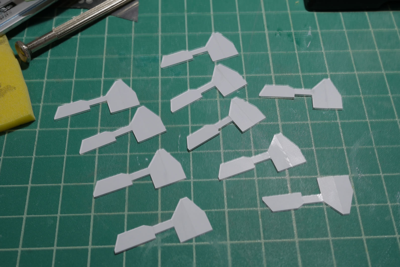
Once the glue cures, I can start sanding down the connection points and then start gluing the pieces together to create the heatsink. The original plan was to place the sink over the curved surface of the binder, so each individual fin was cut and a separation piece of plastic is glued along the bottom to build the sink.
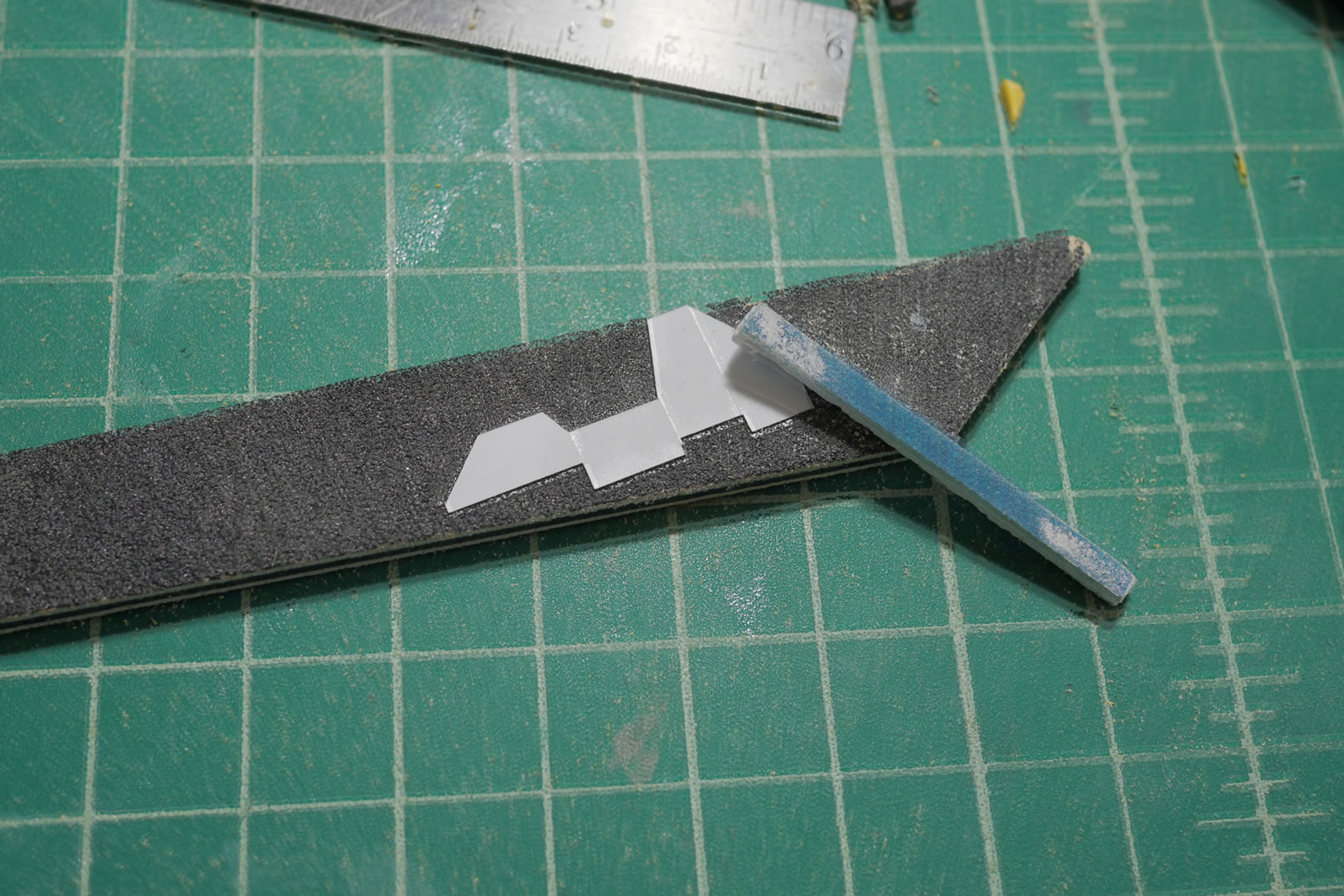
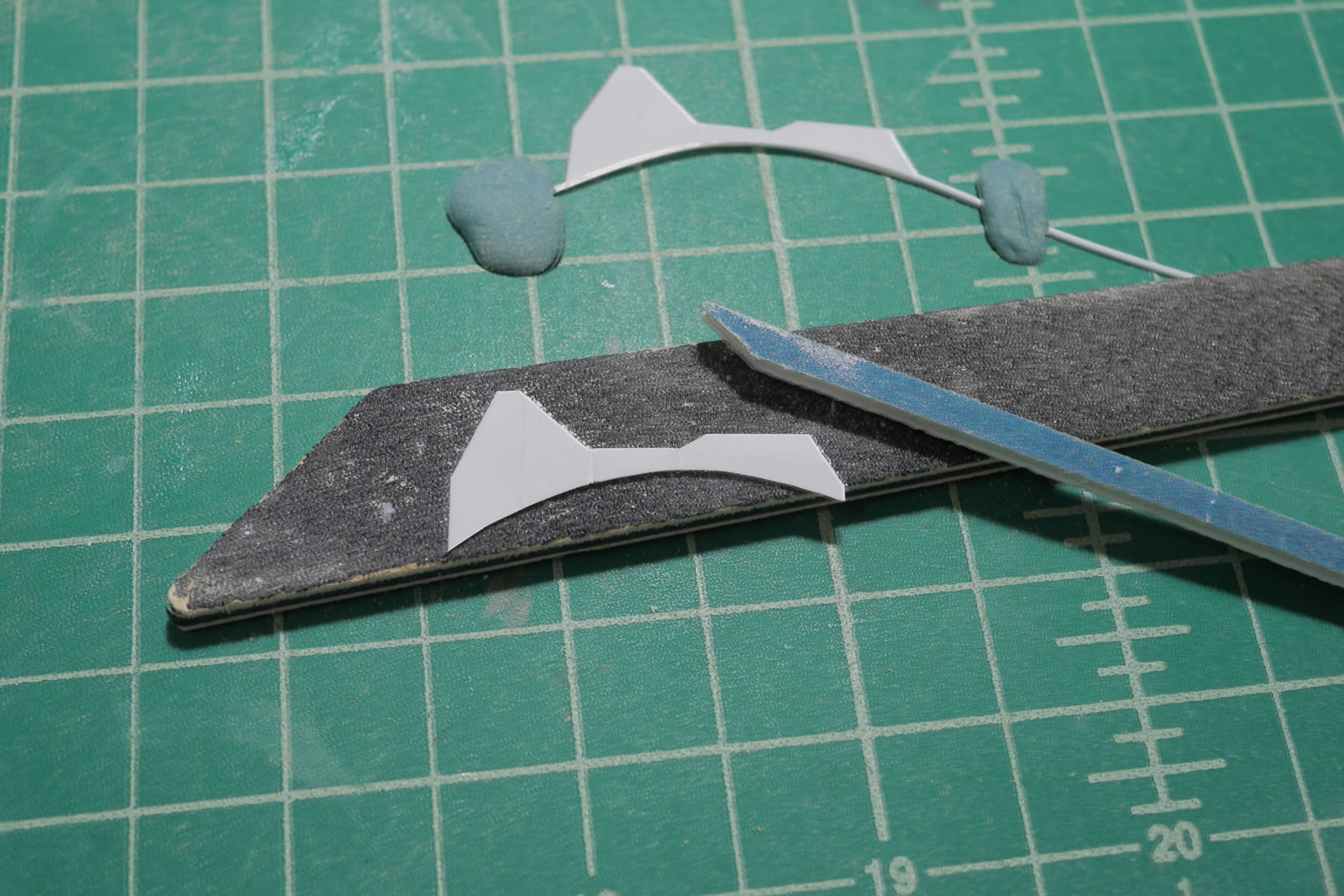
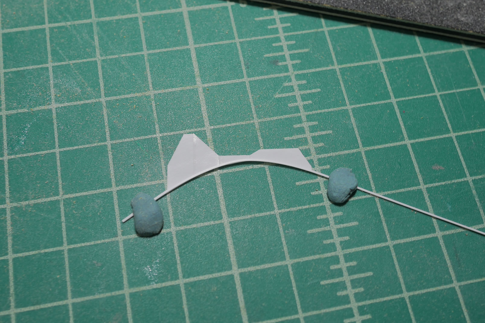
My impatience and the practical placement went out the window and I sort of backed away from this idea.
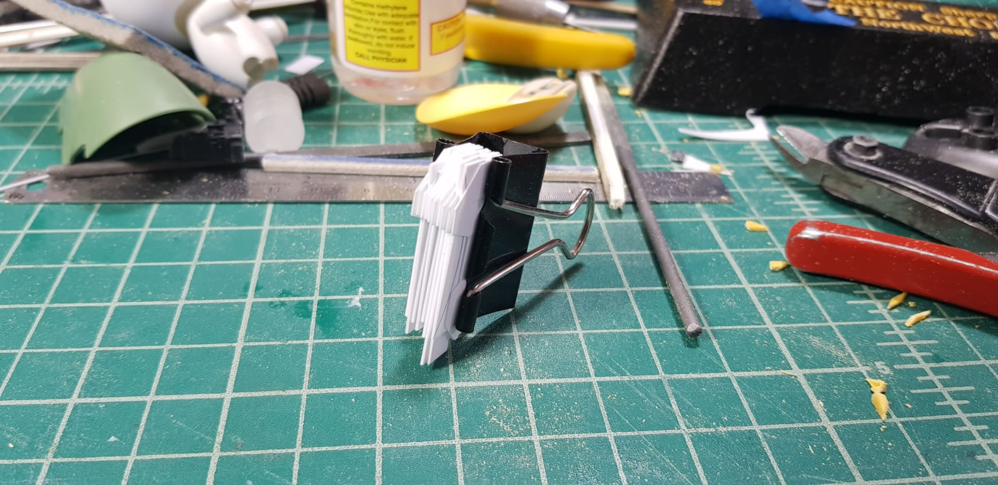
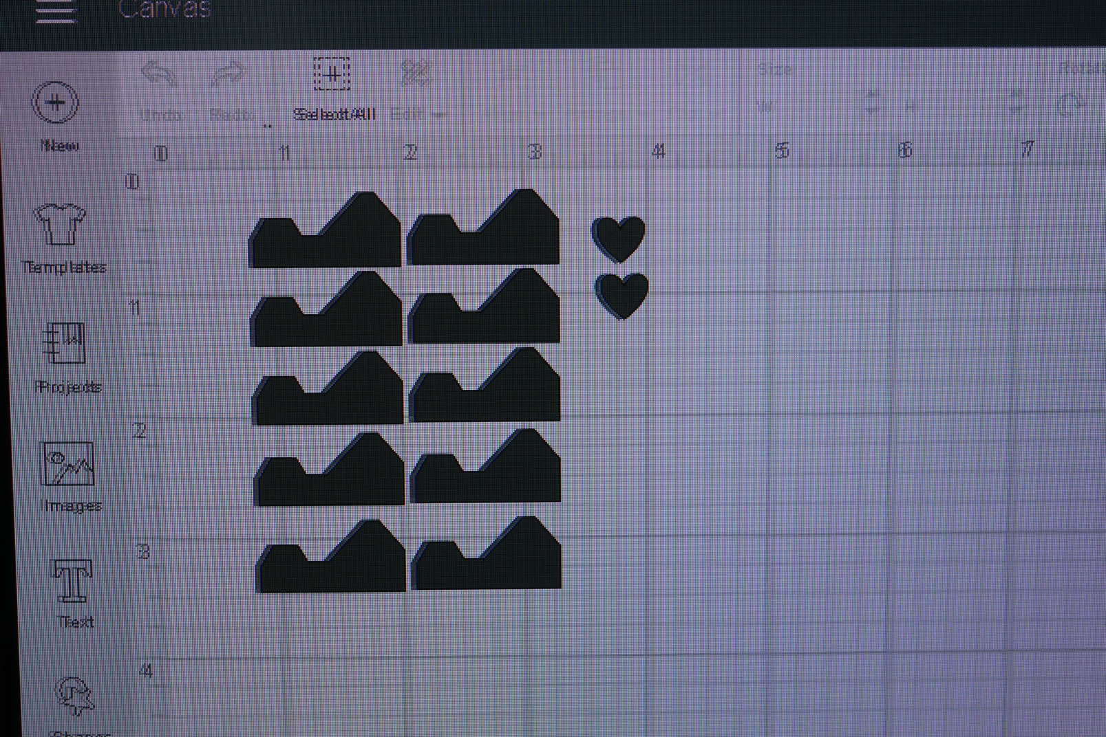
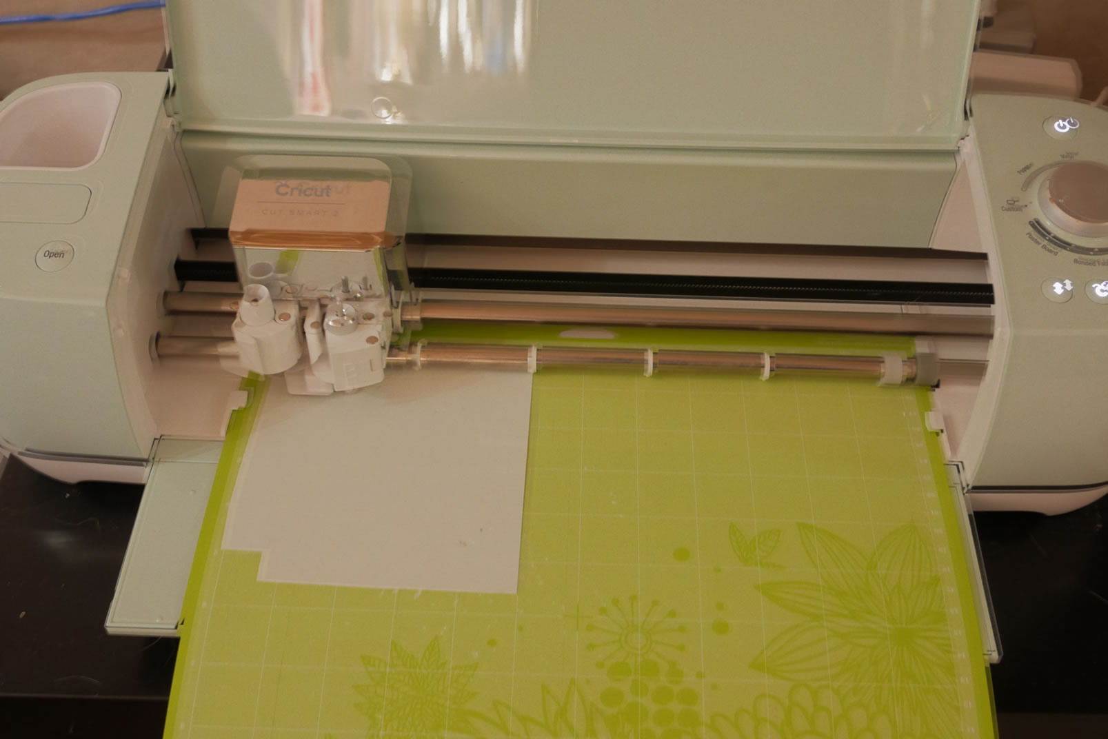
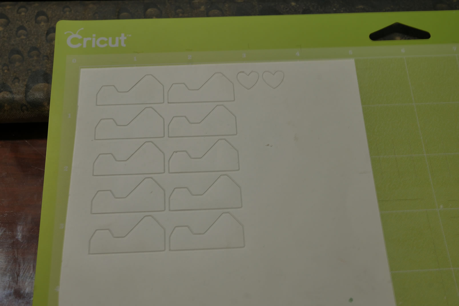
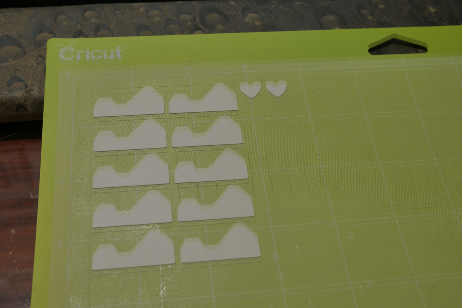
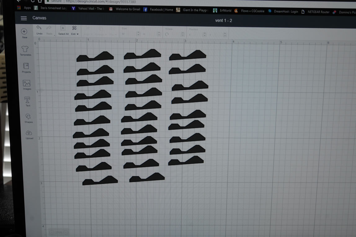
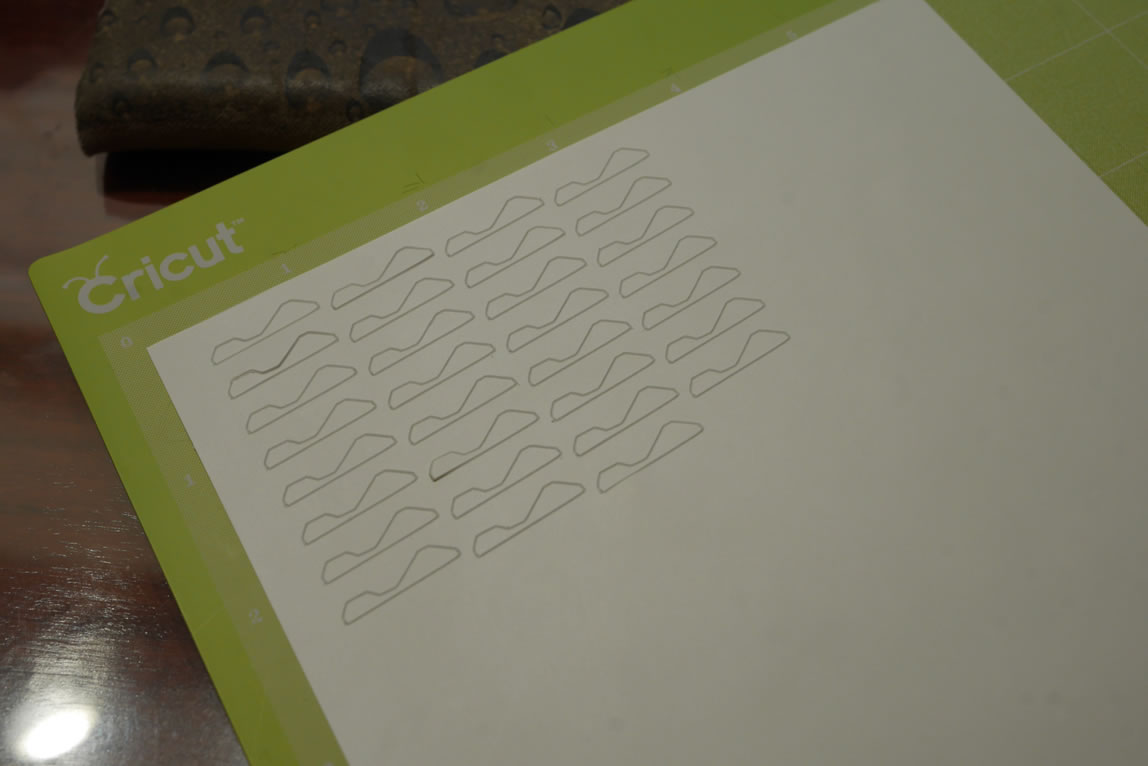
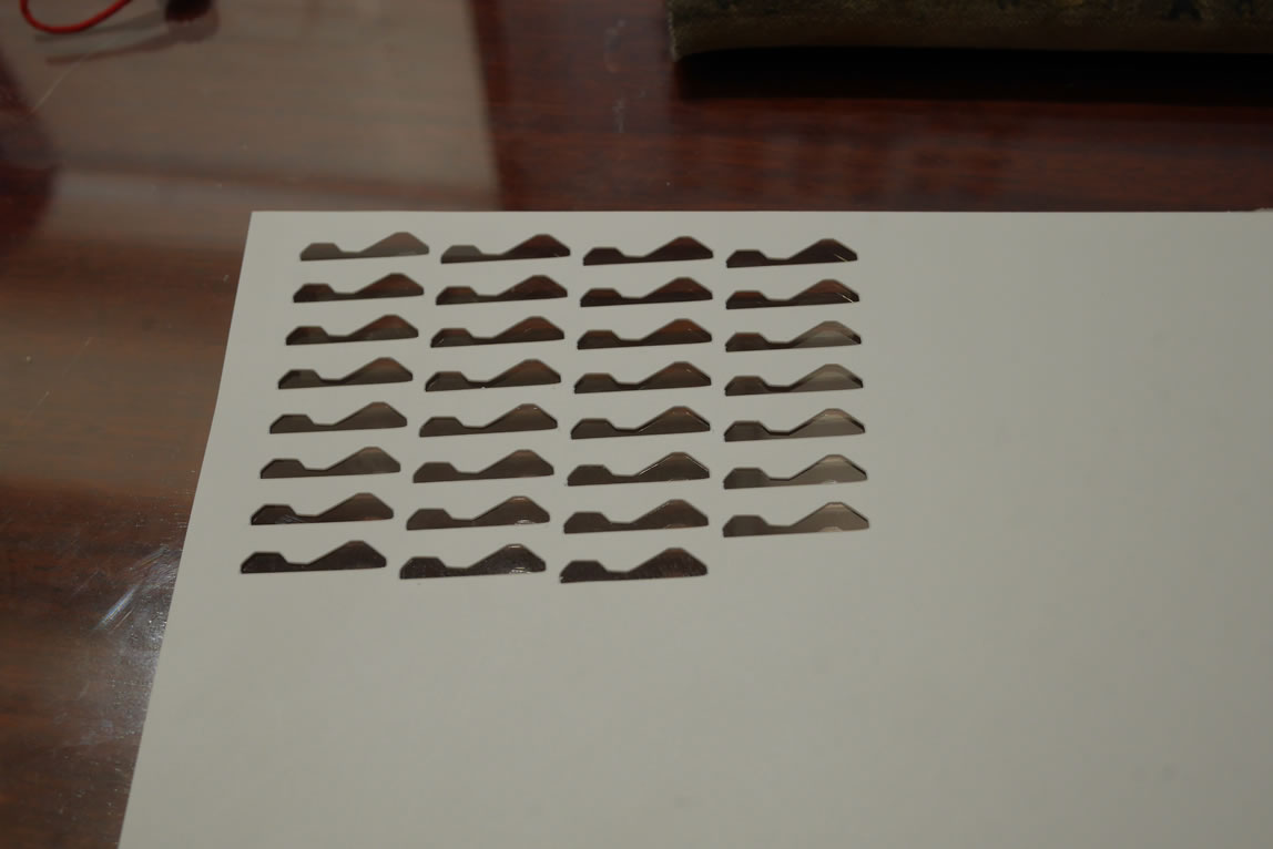
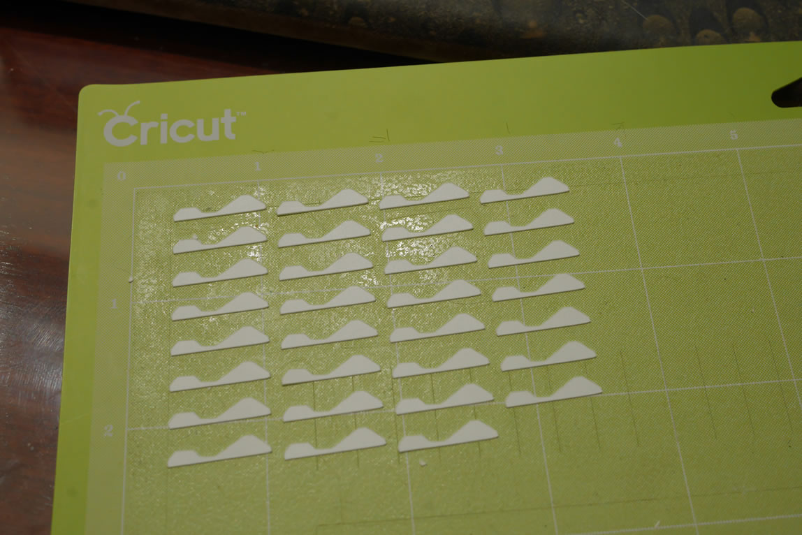
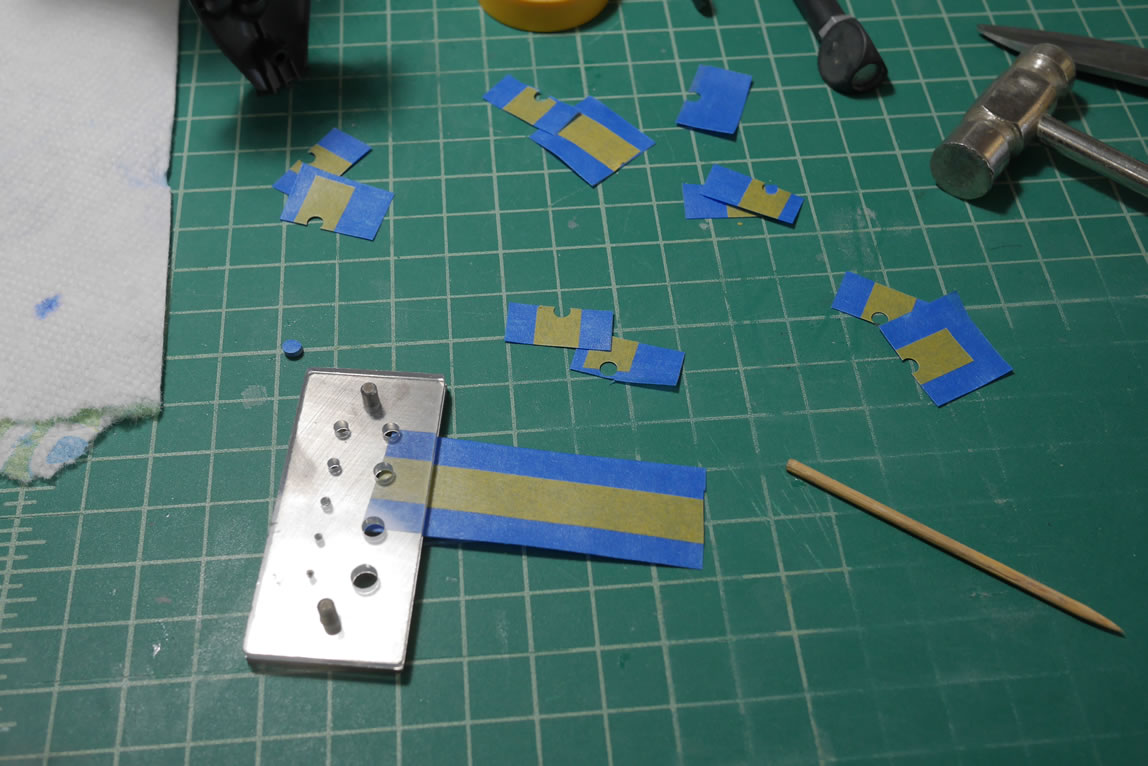
That is until I remembered that I have a cricut cutting machine. I designed a fin piece and made copies in the cricut designer tool. Then placed a sheet of 10mm thick plastic onto the cutting template and ran the machine. This is where I made 10mm heart shapes that I glued to the motorcycle helmet. Theses fin pieces were perfectly uniform.
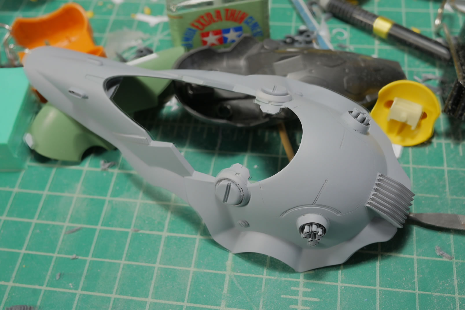
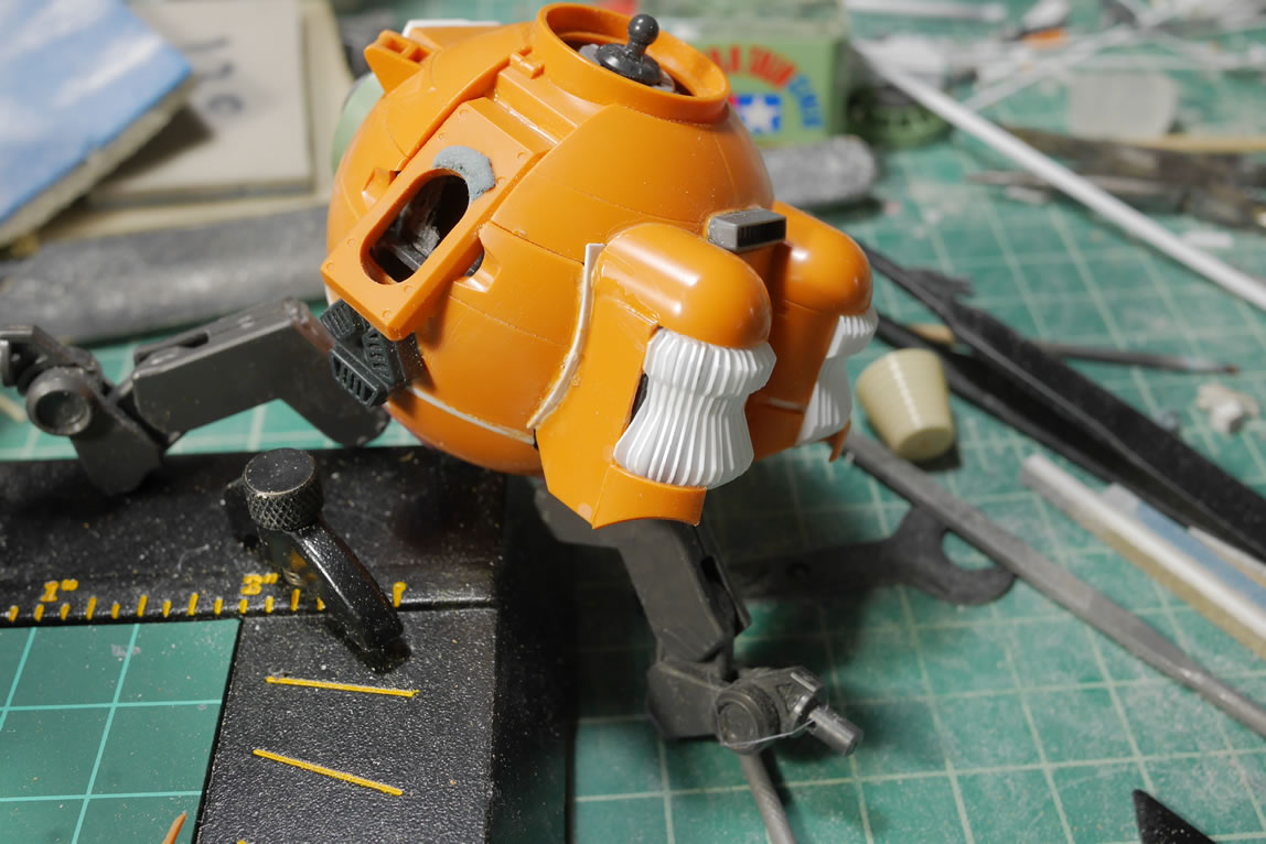
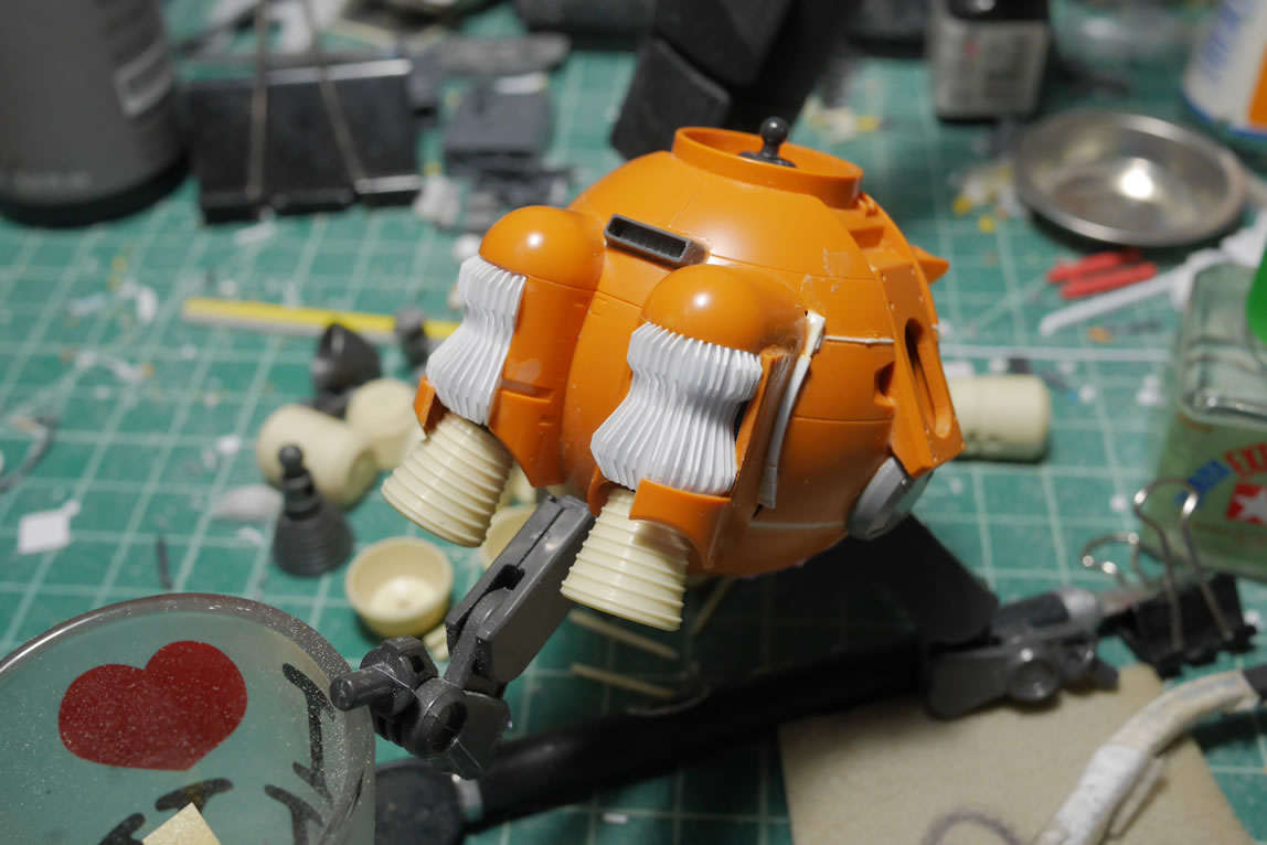
Using the same method as earlier, I created a heatsink for the binder and for the back of the Ball where the thruster engines exist. This worked out much better than the first attempt and I used a plastic tube as the center structure and created a curved vent where for the binder, I used a flat piece and created a flat heatsink. A little note about the ball, I oriented the Ball upside down for its use in my project because things just worked out better with it in that orientation so there is going to be some reworking of other things so that it all sorta normals out.
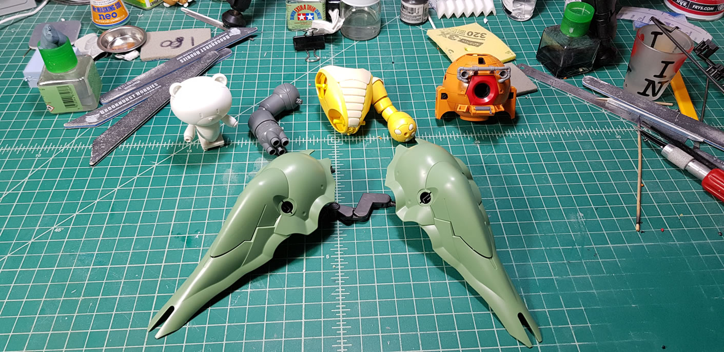
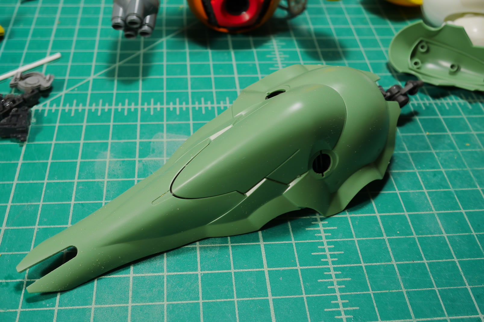
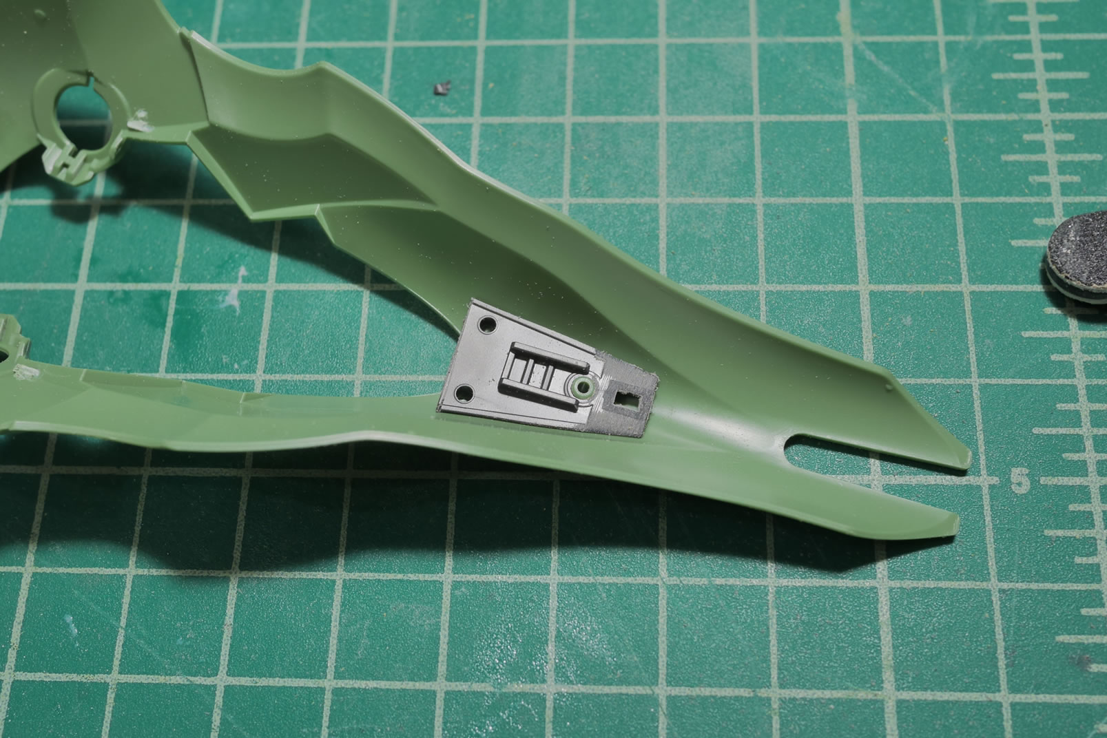
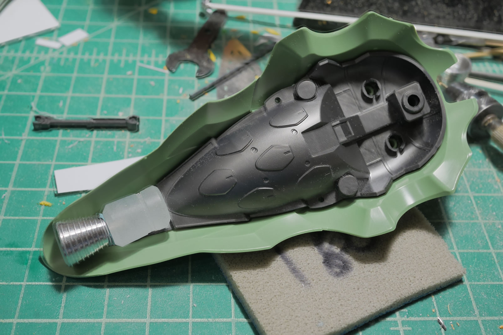
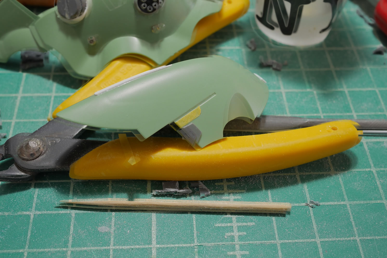
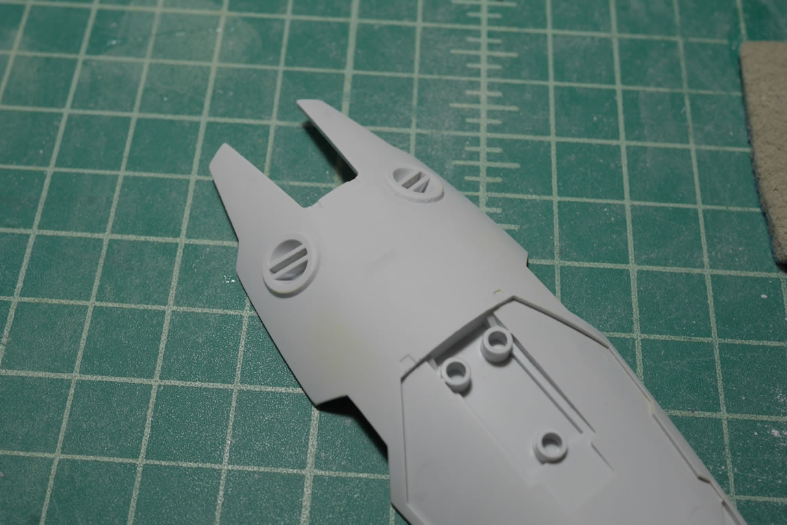
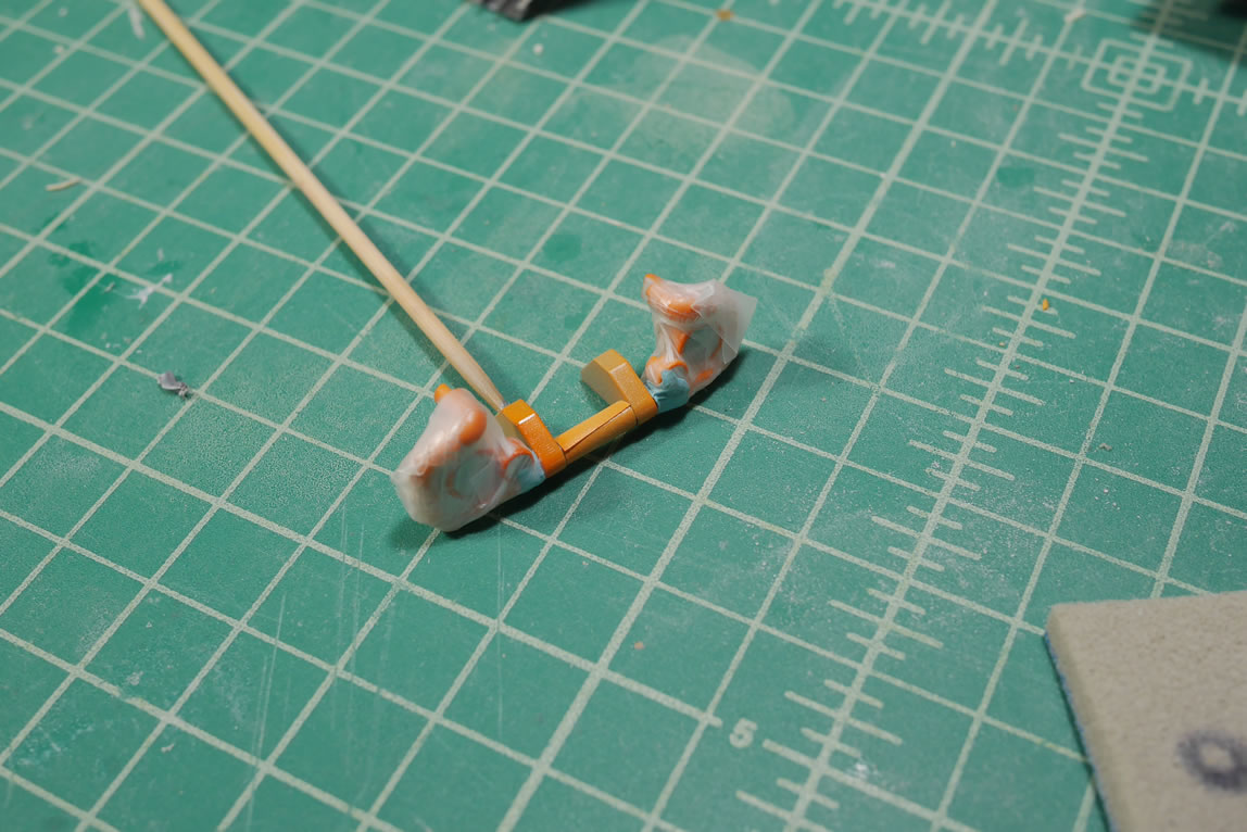
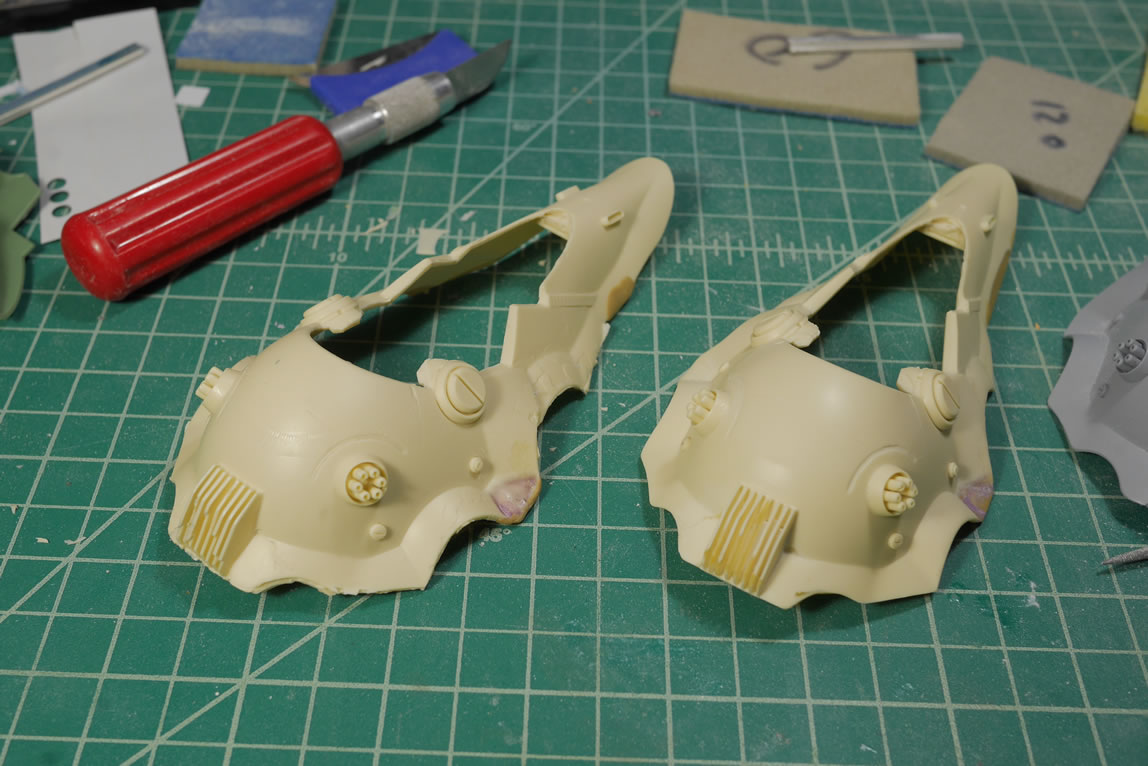
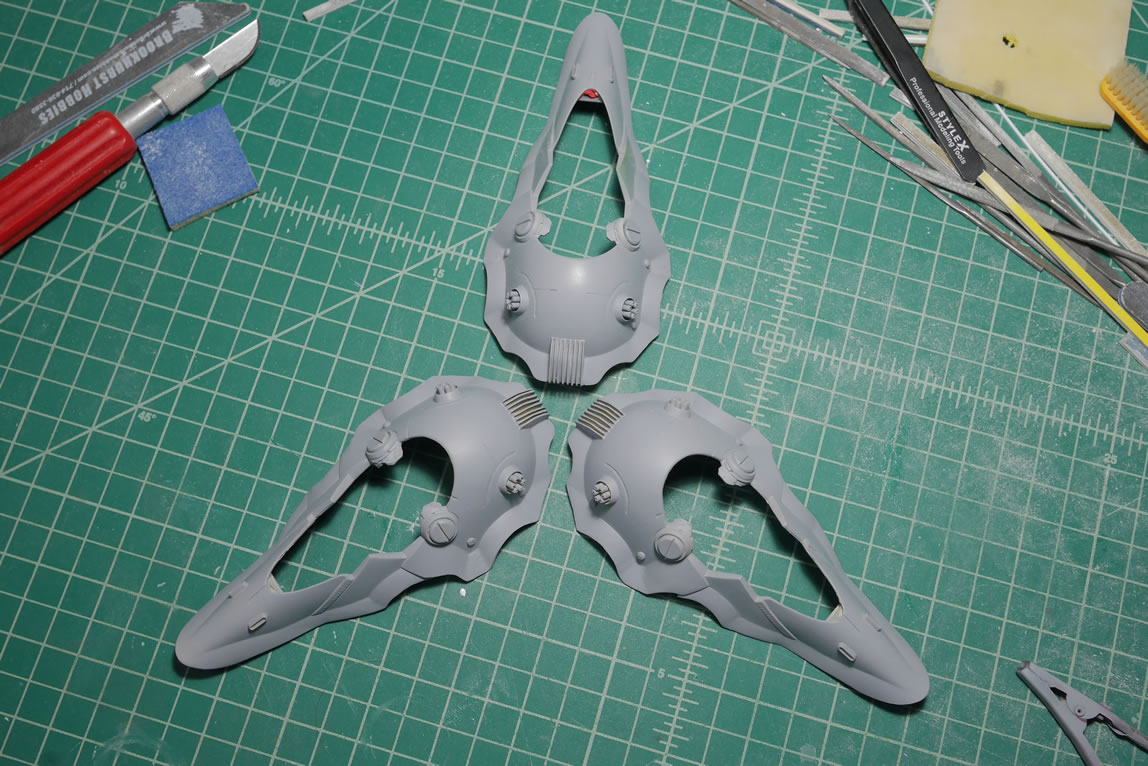
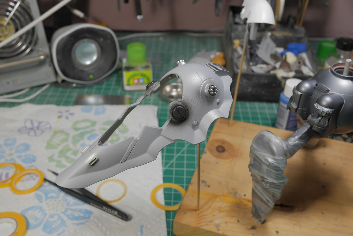
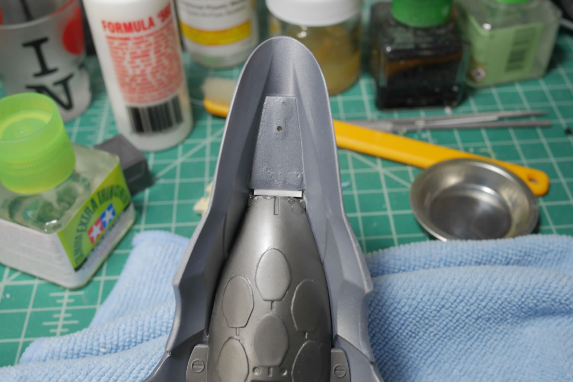
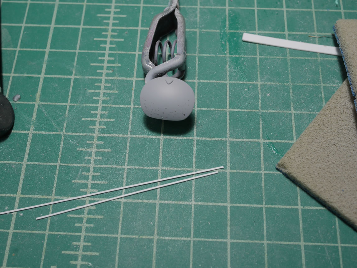
Onward to the binders. I sat for a while thinking about how I wanted to approach the binders. I ended up trimming the front fork off and cutting the tip off the inside frame piece. The idea is that I will be attaching a resin cylindar detail piece from the resin Ore Gun and attach a large thruster bell here. This will sorta be the “foot” thruster. Below is a quick mock up.
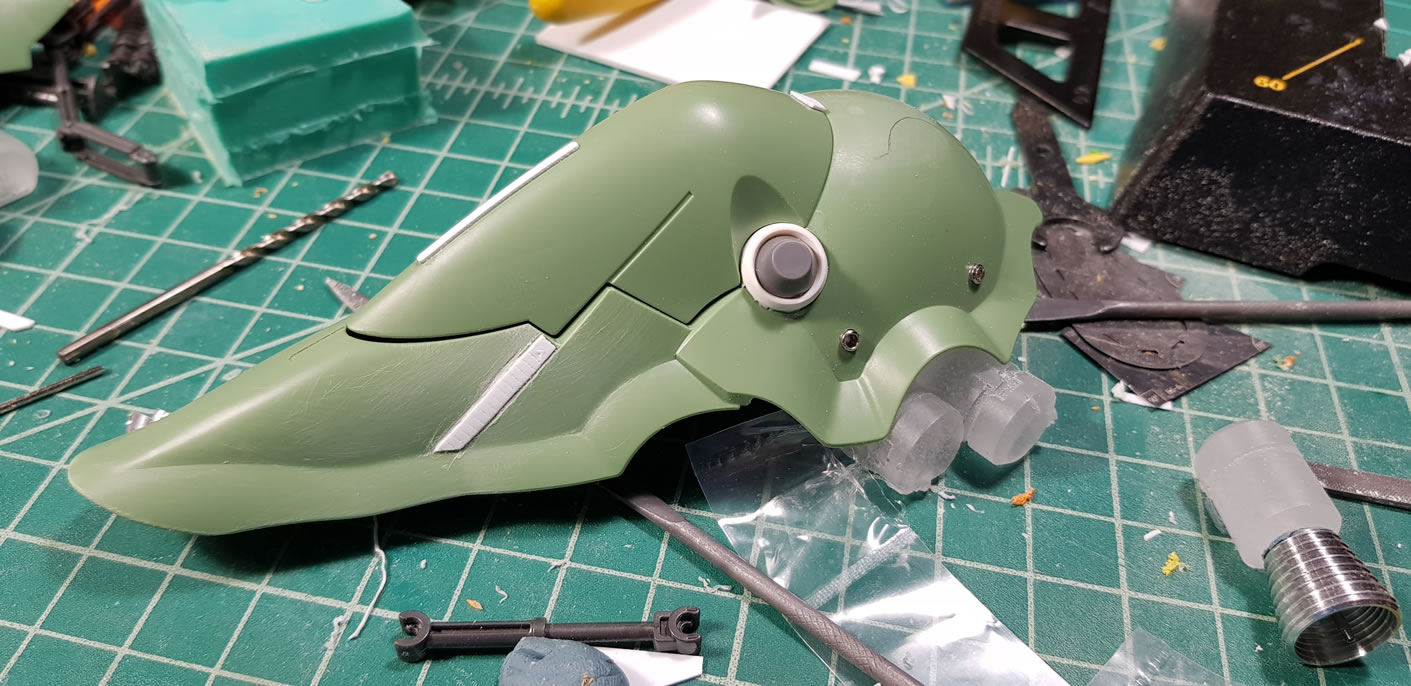
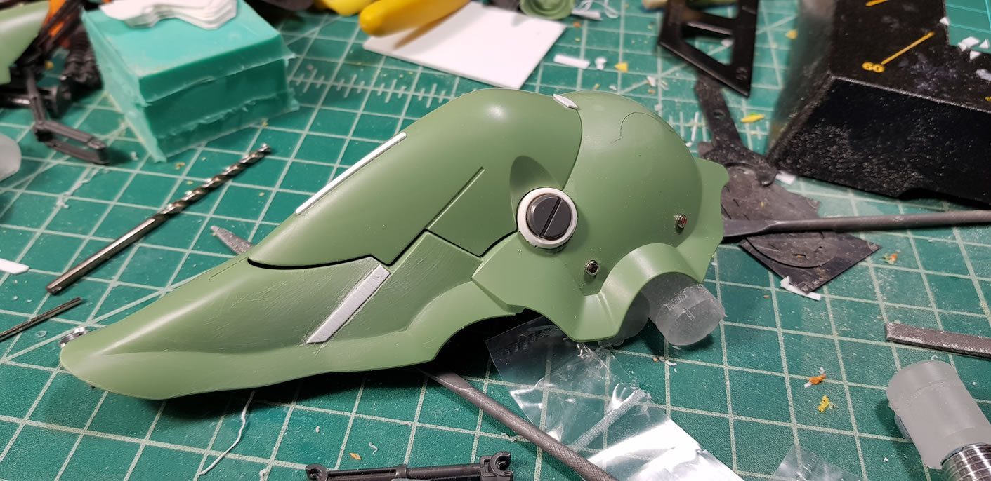
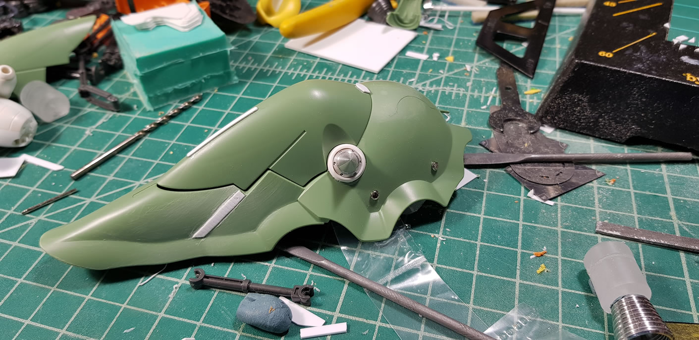
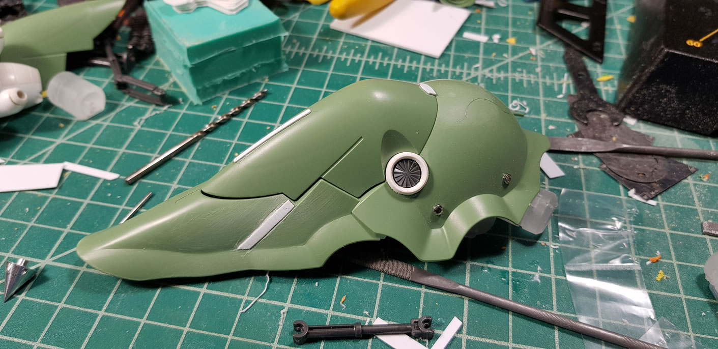
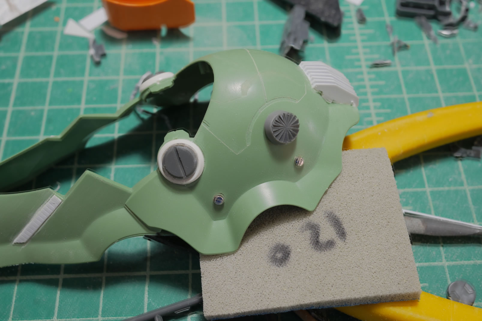
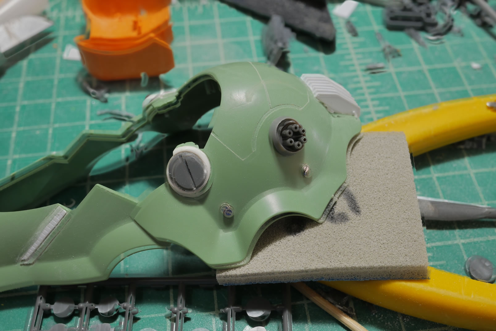
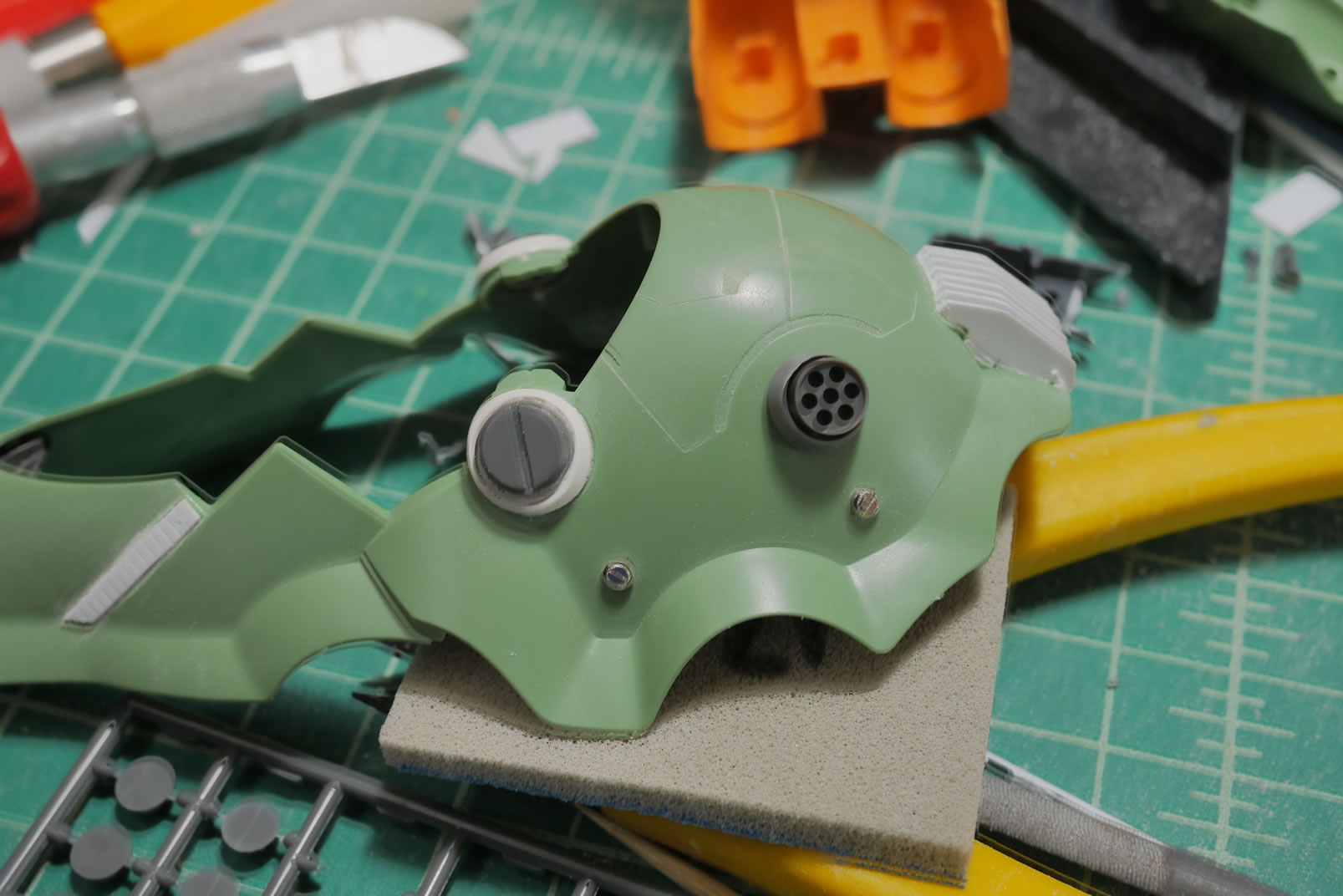
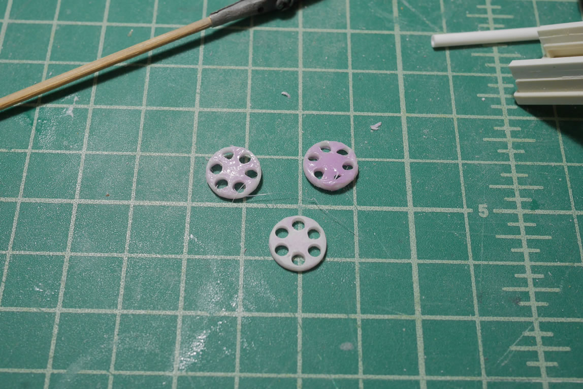
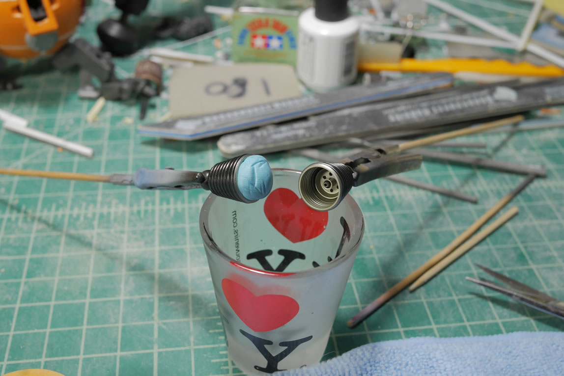
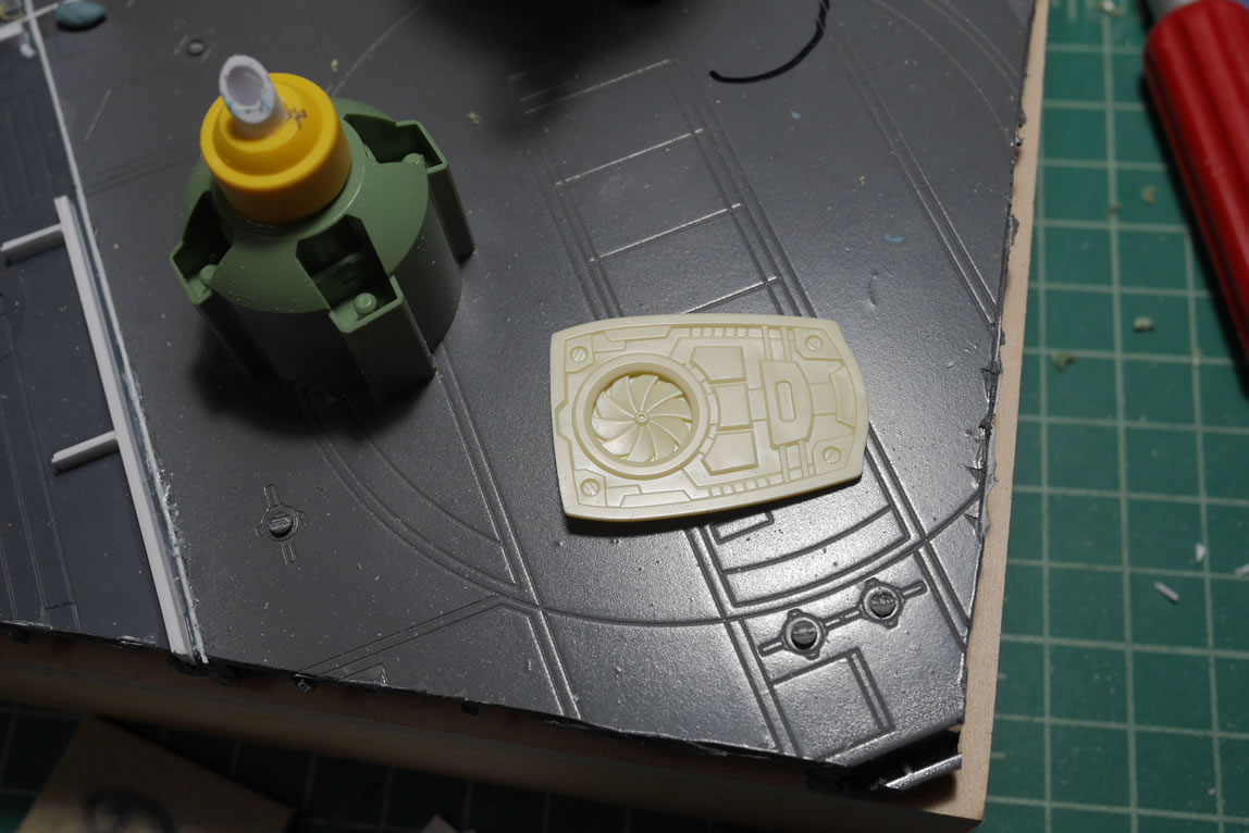
I went to Japan in March of last year so I went and stocked up on a bunch of koto and wave detail bits from the Yellow Submarine shop. I pulled some round detail bits and took pictures of different configurations before settling on the minus mold detail. It was fun to get a good look at all the possibilities. Here I have the original design and the design I picked.
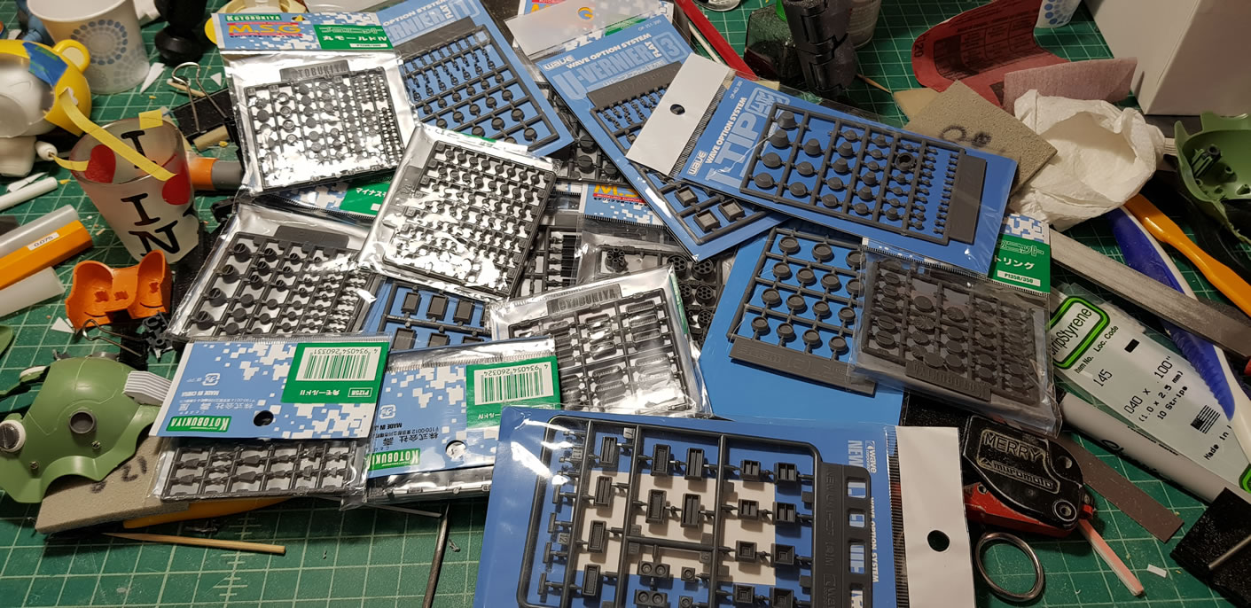
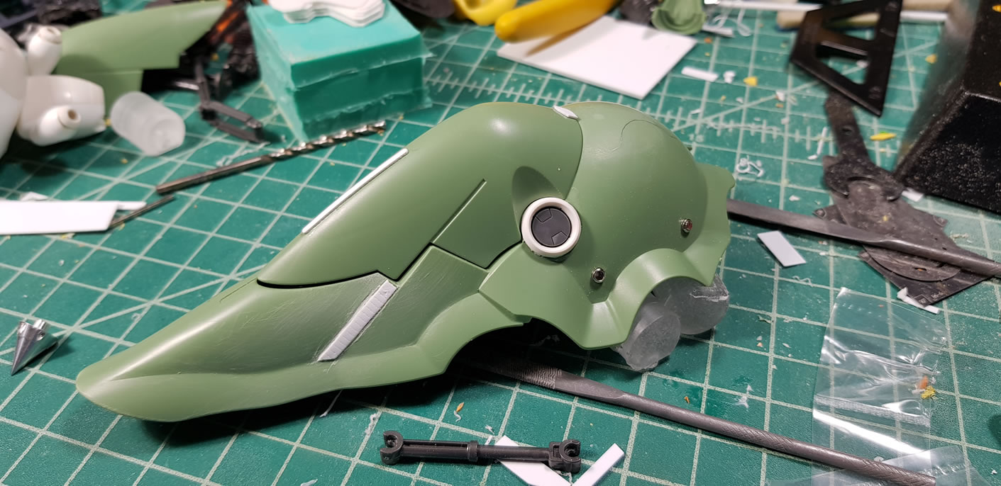
Below are the other options. For the sake of argument, I posted the variants on FB to see what kind of response. The two top choices was the turbine detail and the minus mold detail, turbine being the first. I had posted after I already glued the minus molds in place, so it was interesting to see how my choice fared against the general populous. I was pretty damn close.
 \
\
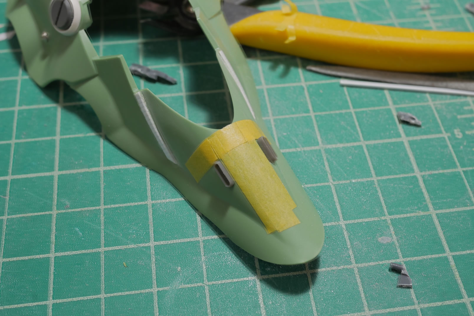
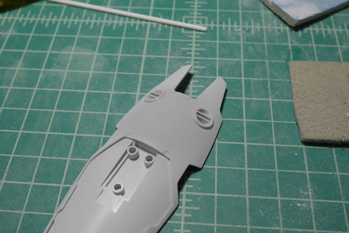
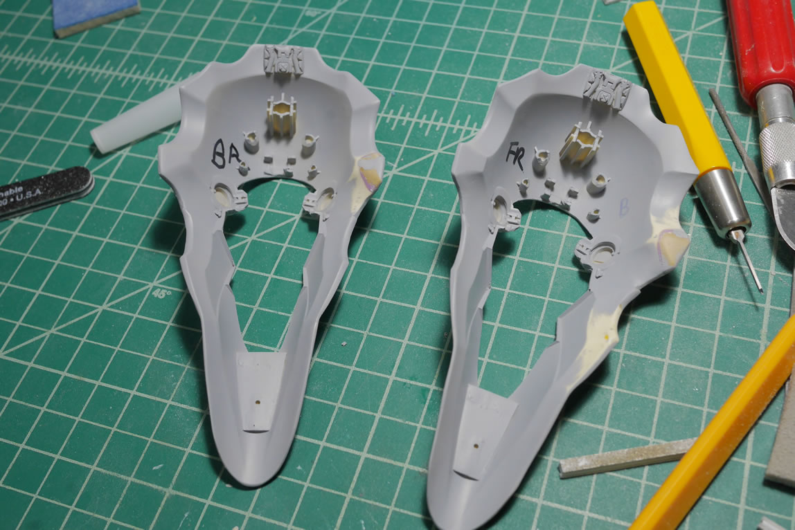
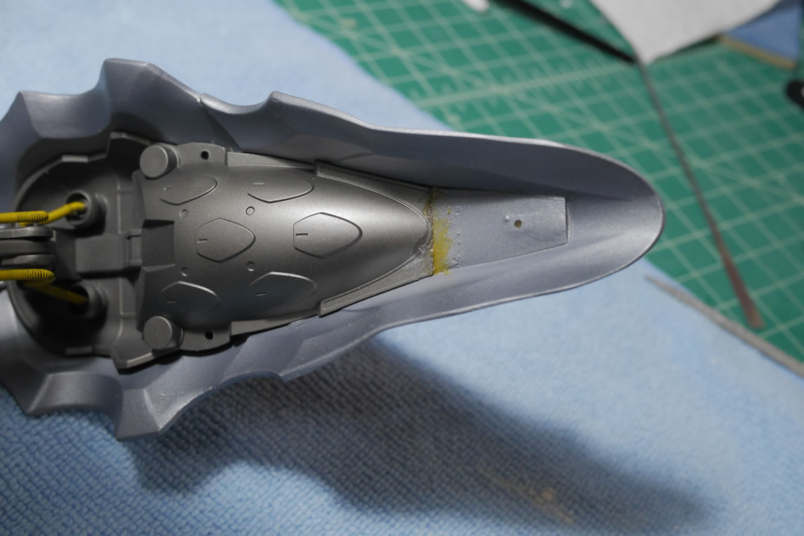
Next up is to do some scribing. I used the cricut cutting machine to draw out a design and cut some masking tape and vinyl tape to lay out a design for the scribing. And once I finished, I realized that the symmetry was completely off. I also realized that the location of the scribing didn’t look good either.
It’s just plastic, so out comes the putty and after sanding, the surface is ready for another go at scribing. I printed more templates, but this time took some extra care with laying down the templates by using some tamiya masking tape as guides. This really helped out the symmetry. Some dyno tape is also employed for some extra lines I didn’t cover in the template design.
I think this looks better than the originally scribed lines. And they’re much more symmetrical.
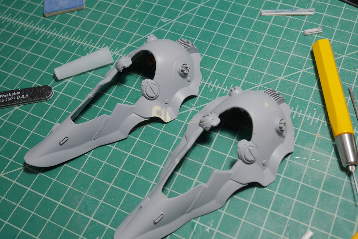
I made a few designs for heat sinks, and was also testing the cricut machine. This time I used a .2mm thick piece of plastic sheet and made some cuts. Then glued together the parts as described above to create another heat sink. This was then glued onto the top of the binder piece filling in the gap at the top. I wanted some detail in the back, so I found a leg piece in my box of parts and cut it out to size and just glued that to the back. As simple as that, I have my detail for the back of the heat sink.
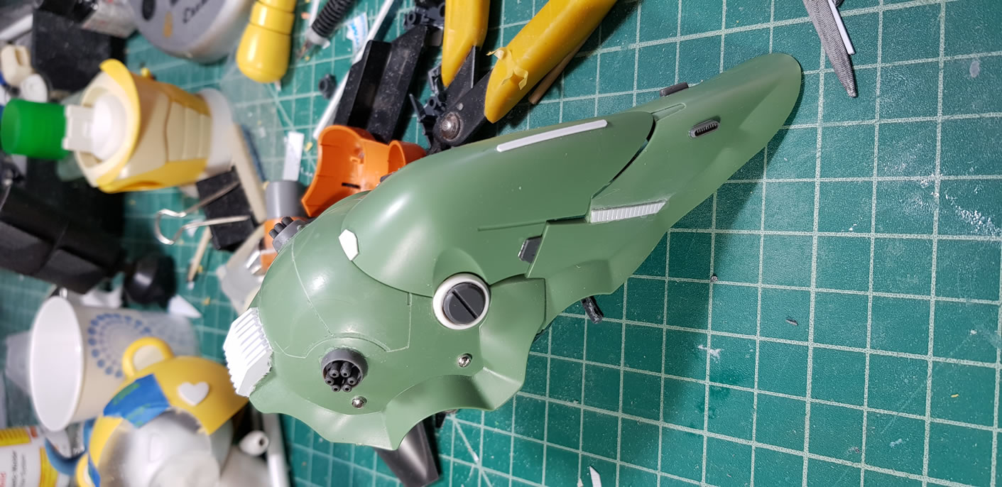
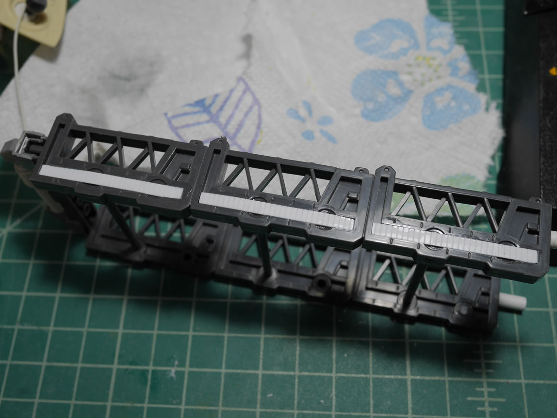
The scribed curve area just begs for some detail, so more koto and wave detail bits and I now have dual gats on the top of the binder. I also took the time to decide on what I wanted as the detail bit as well. Context is key. Since the binders are not really binders but legs, the detail bits sort of work.
I added more koto parts to the top piece of the binder (tripod leg), as well as some vents to the bottom of the tripod leg.
Detailing for the leg is done and I have a comparison with the out of box binder. A quick spray of primer shows the mistakes that need to be fixed.
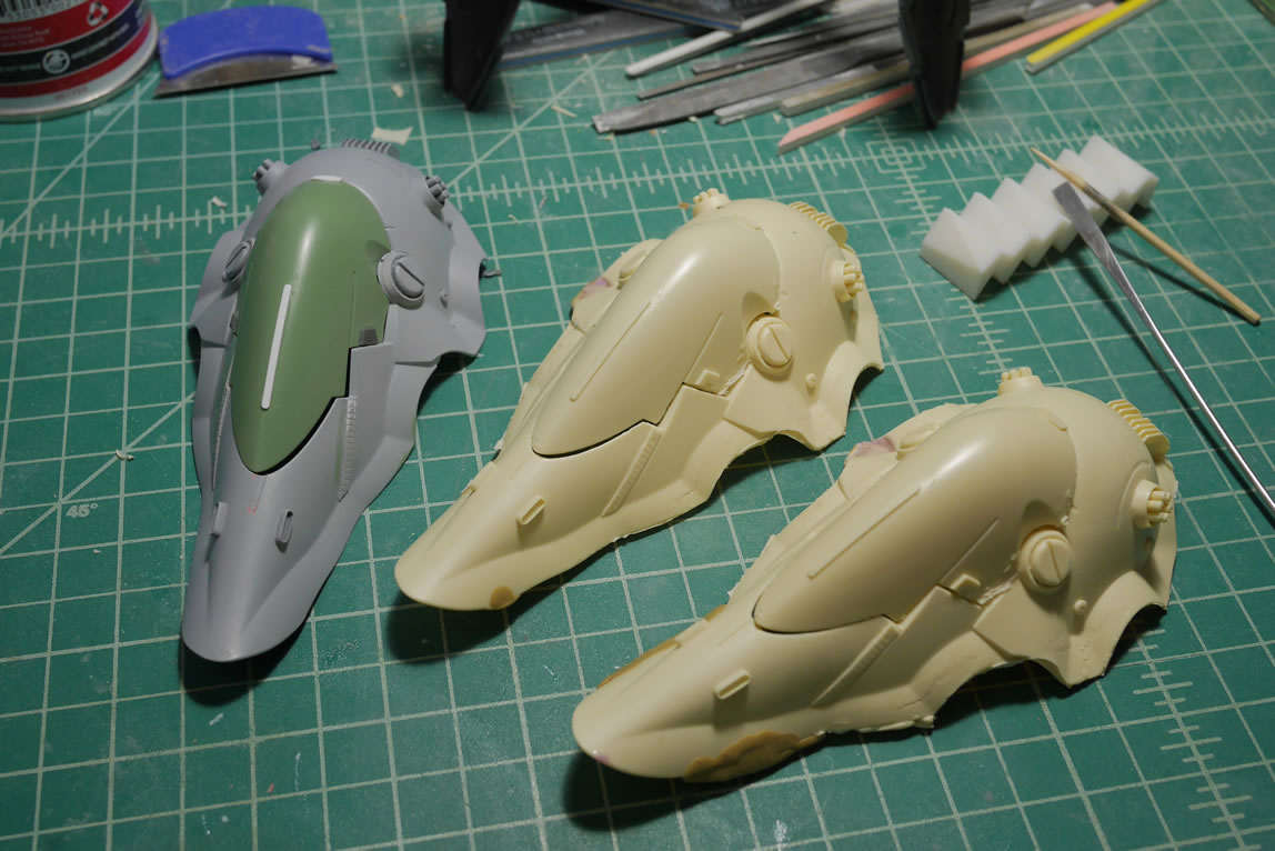
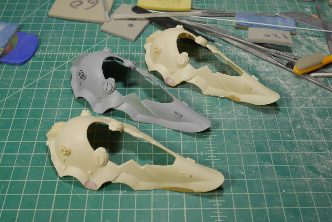
Since I need 3 legs in total, I figured I’d just make one modification and then mold it and make copies. This sorta works. I end up using a huge amount of silicone. So the value vs work of just building the three binders is arguable. I think I made the better choice. I did two halves for the mold similar to the bg face. The playdough is used to fill in negative spaces so I don’t use that much silicone. The second pour of silicone also had old cured molds added to help offset the amount of fresh silicone required. Silicone sticks very well to itself so old mold can be cut up and used as filler. Once done, the original is removed and the mold is prepped for the first resin pour.
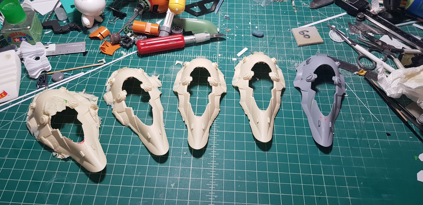
The first pour is always a shit show. It usually works to help clean out the mold and also works to test how to actually pour and work with the resin in this mold. I made three more pours before I got 2 good enough copies. There is a huge amount of cleanup and fixing, but I think it beats the hell out of trying to bash/scratch identical pieces.
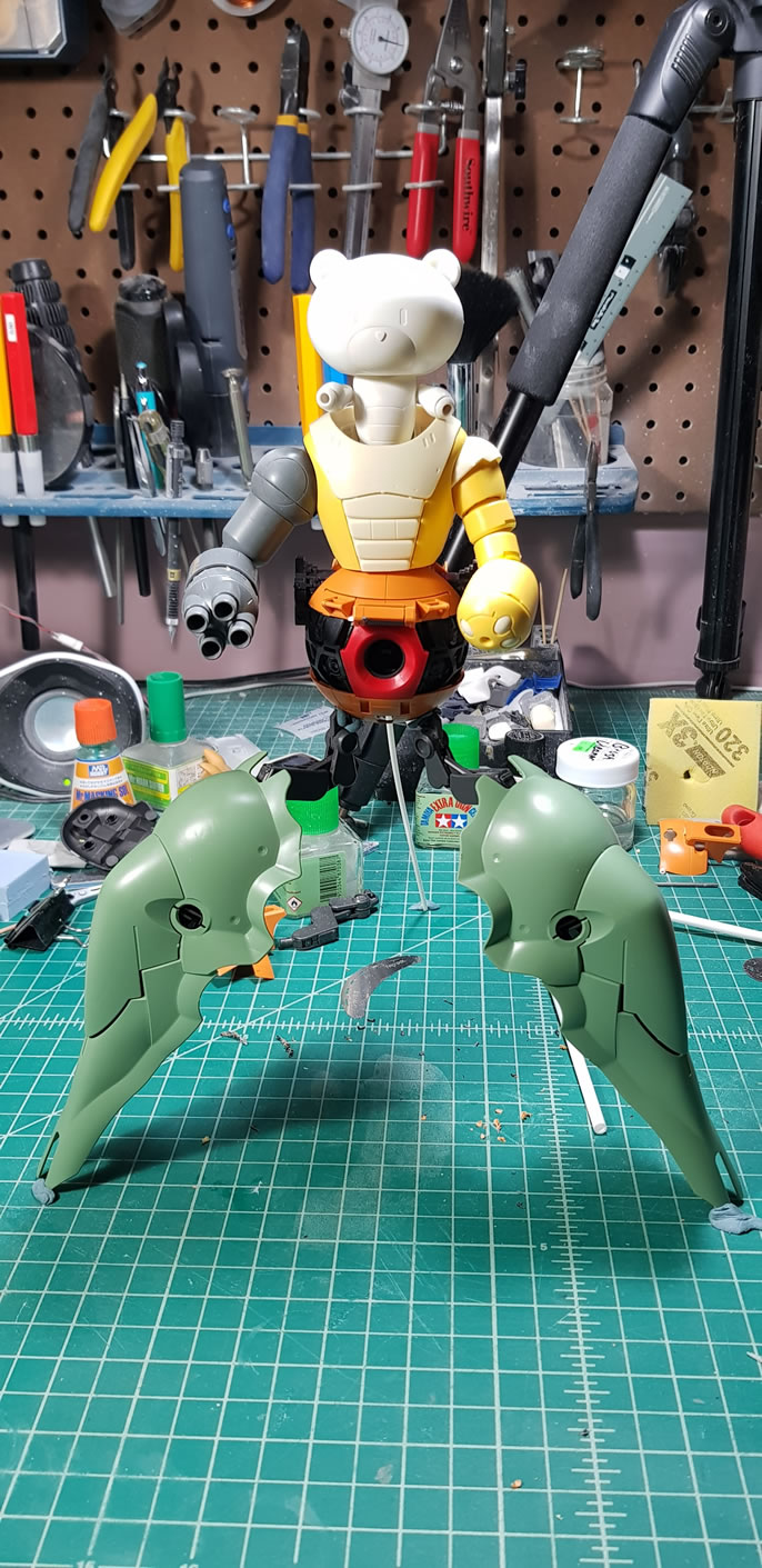
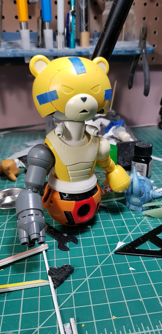
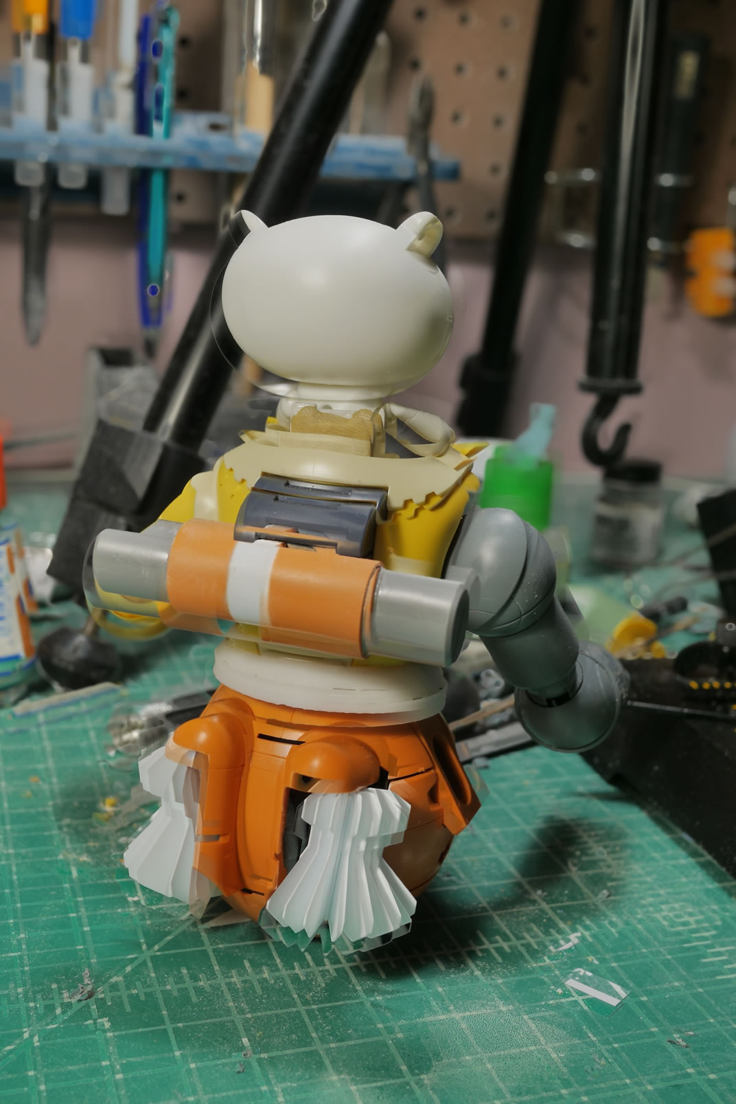
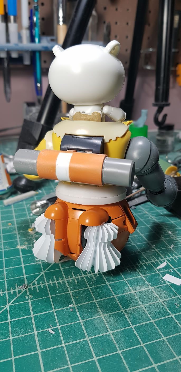
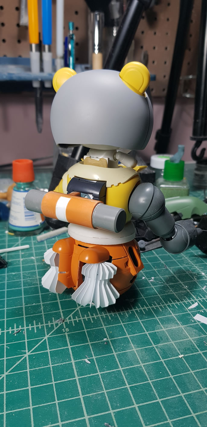
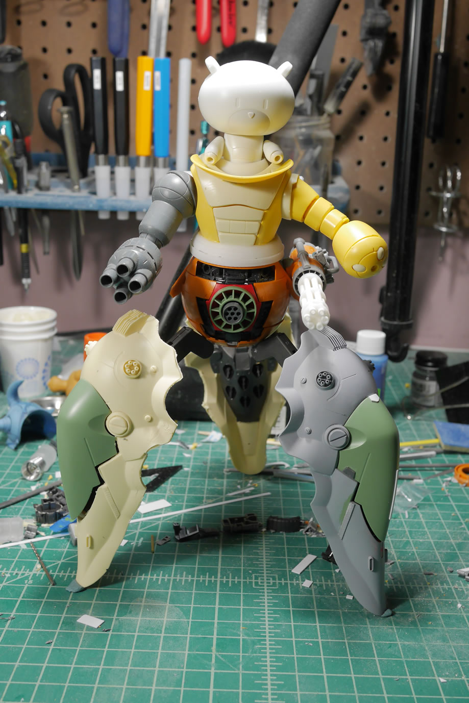
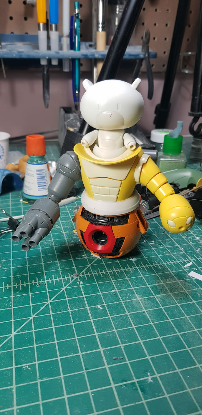
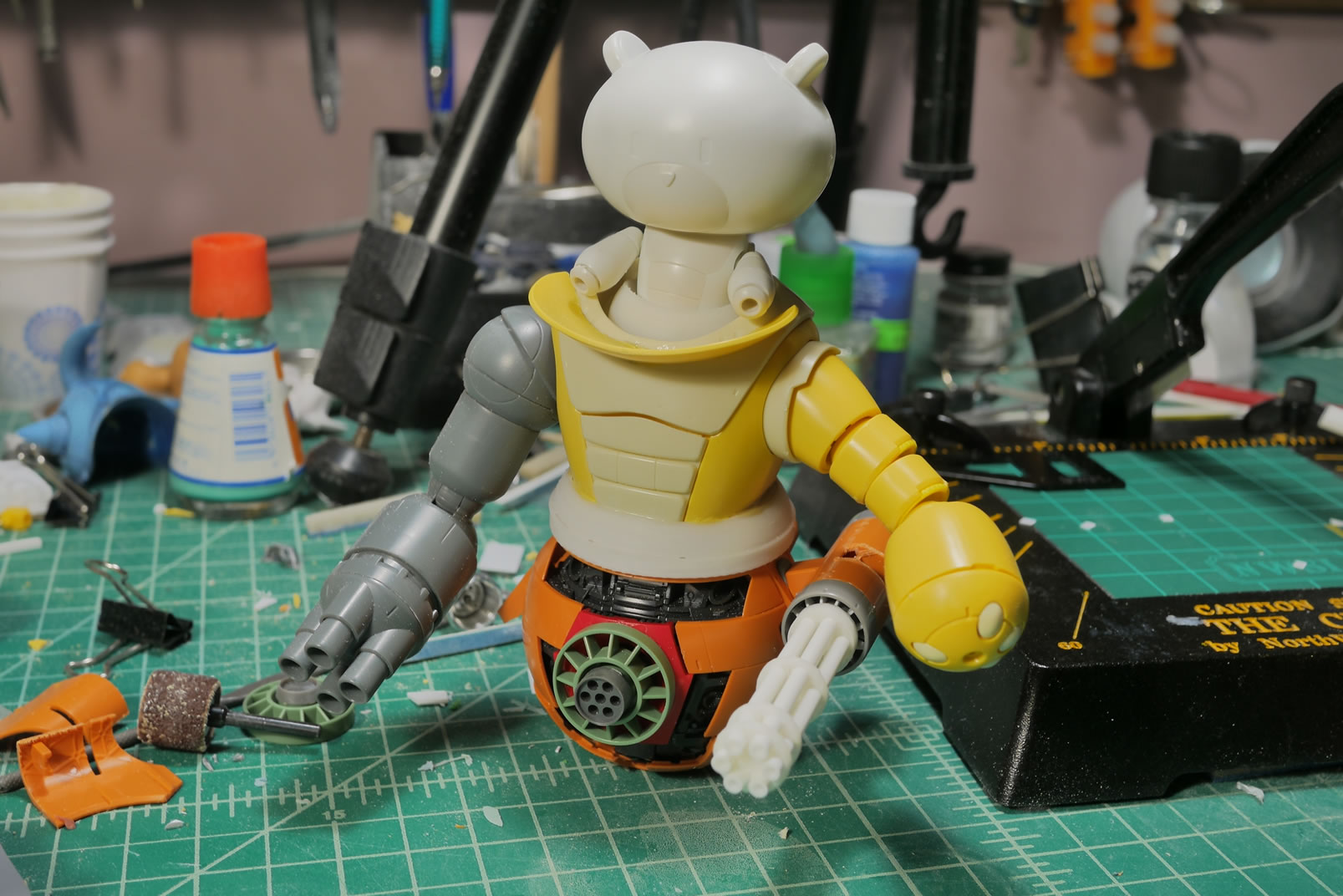
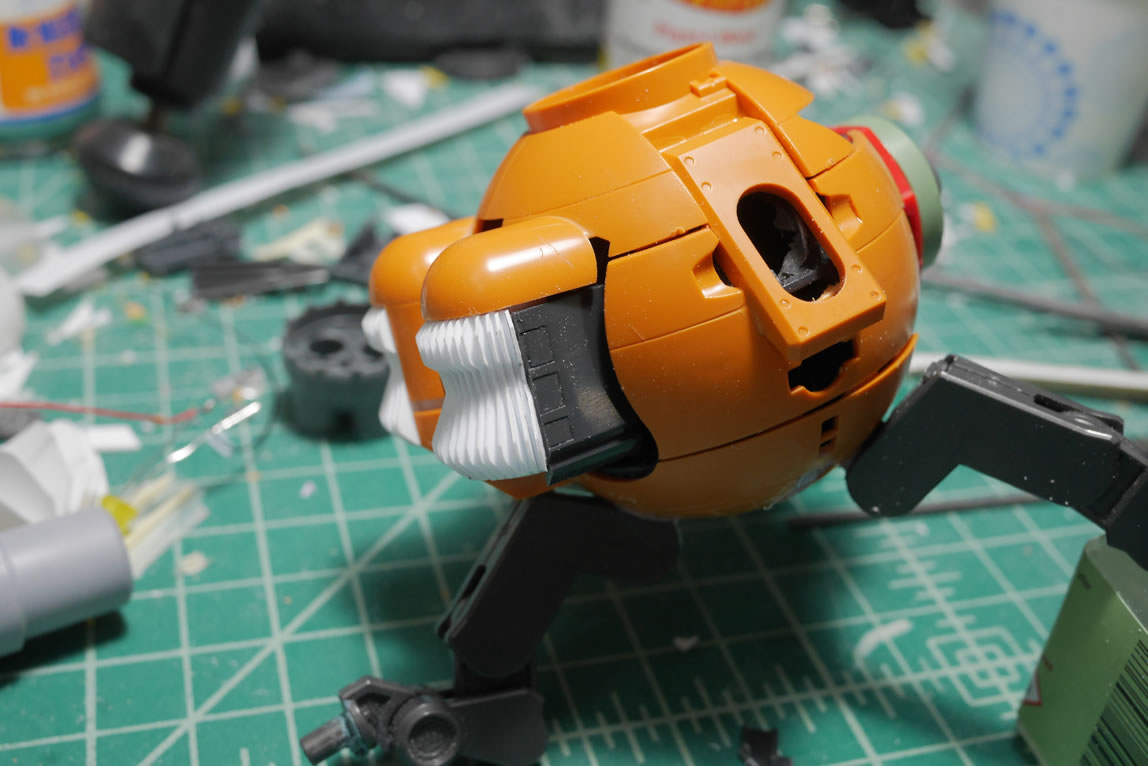
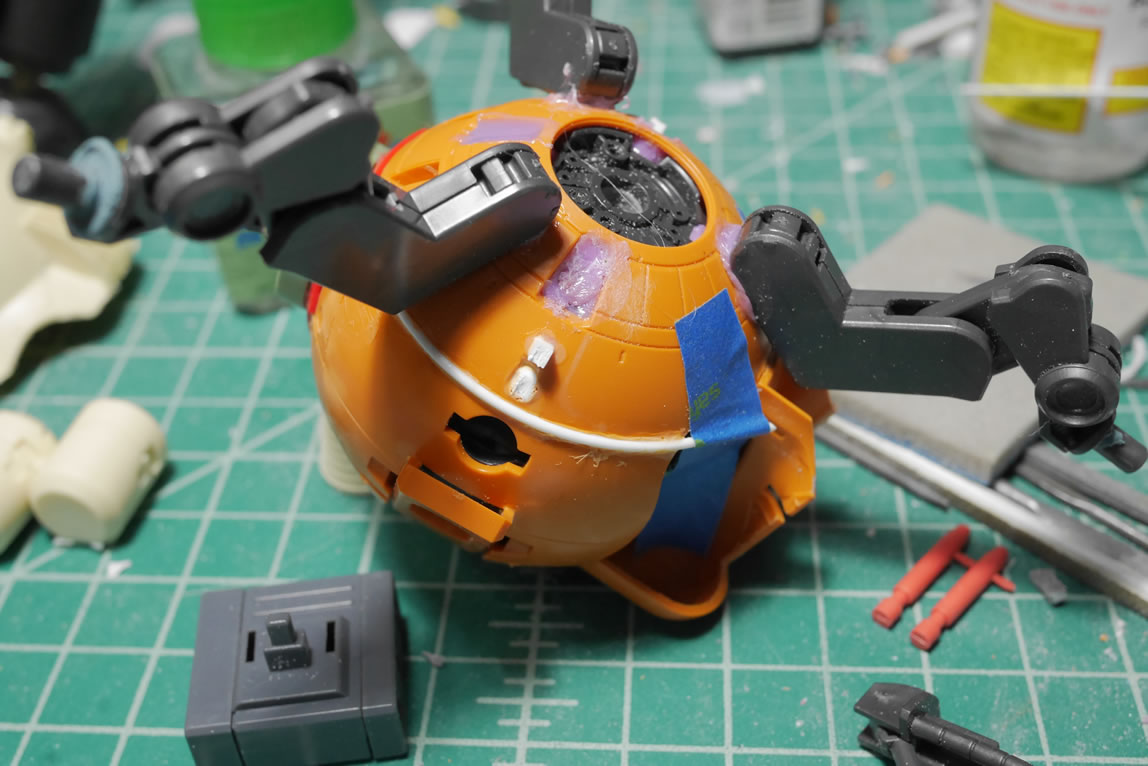
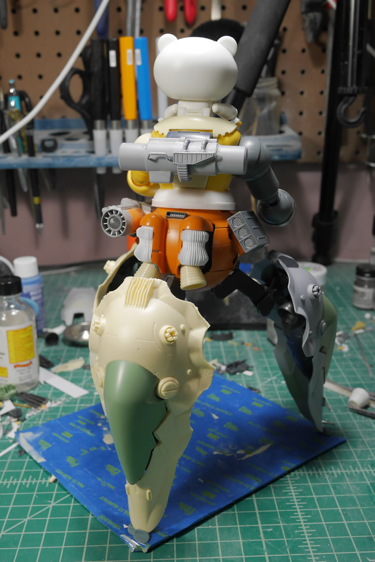
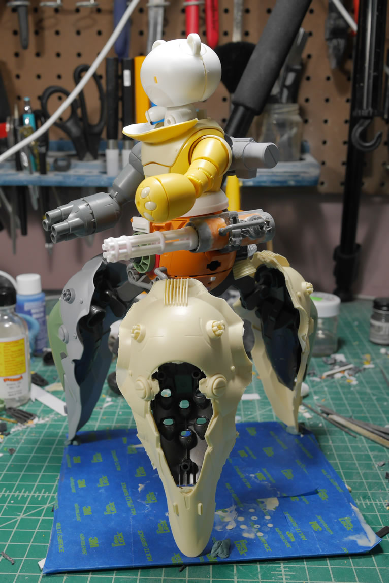
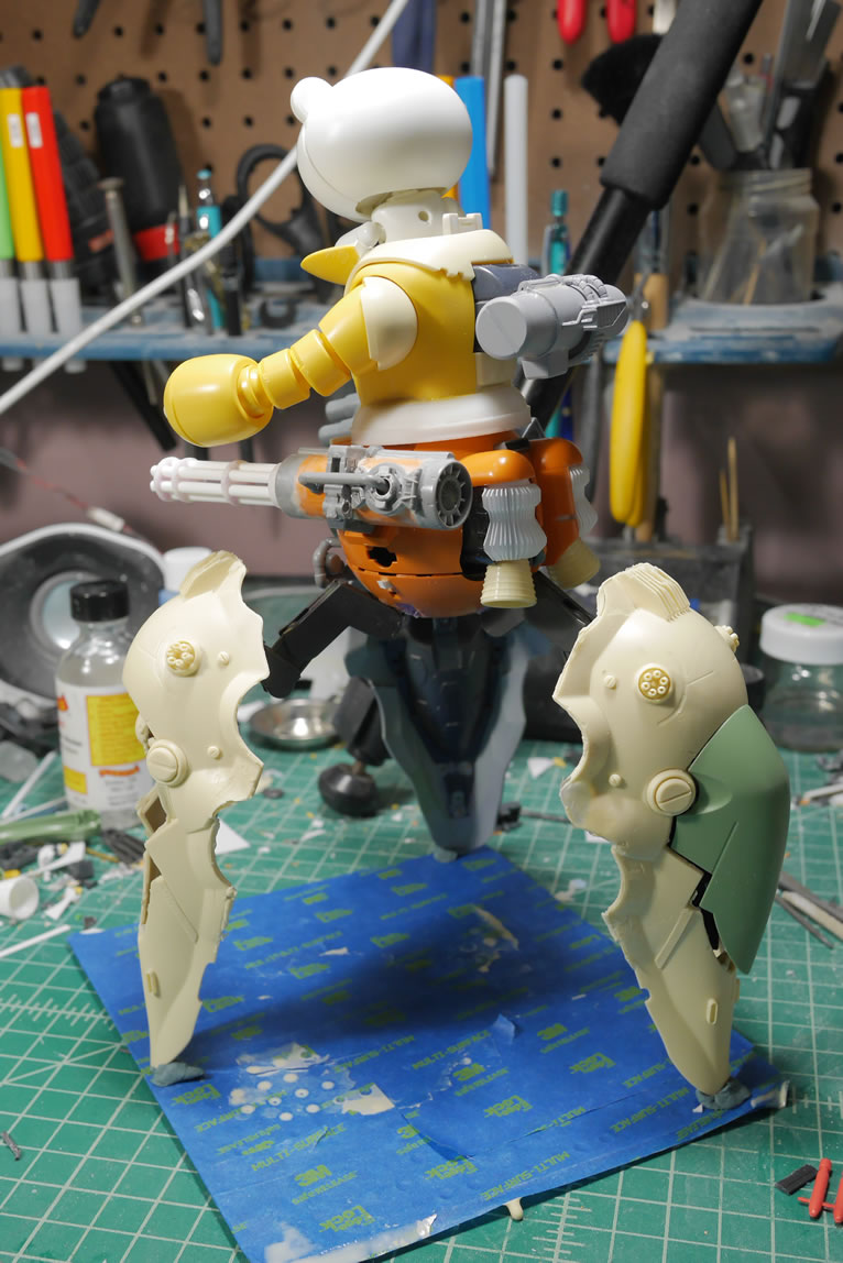
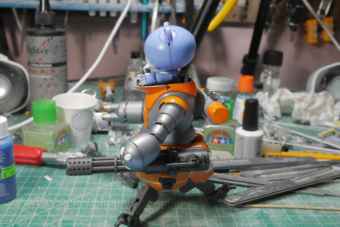
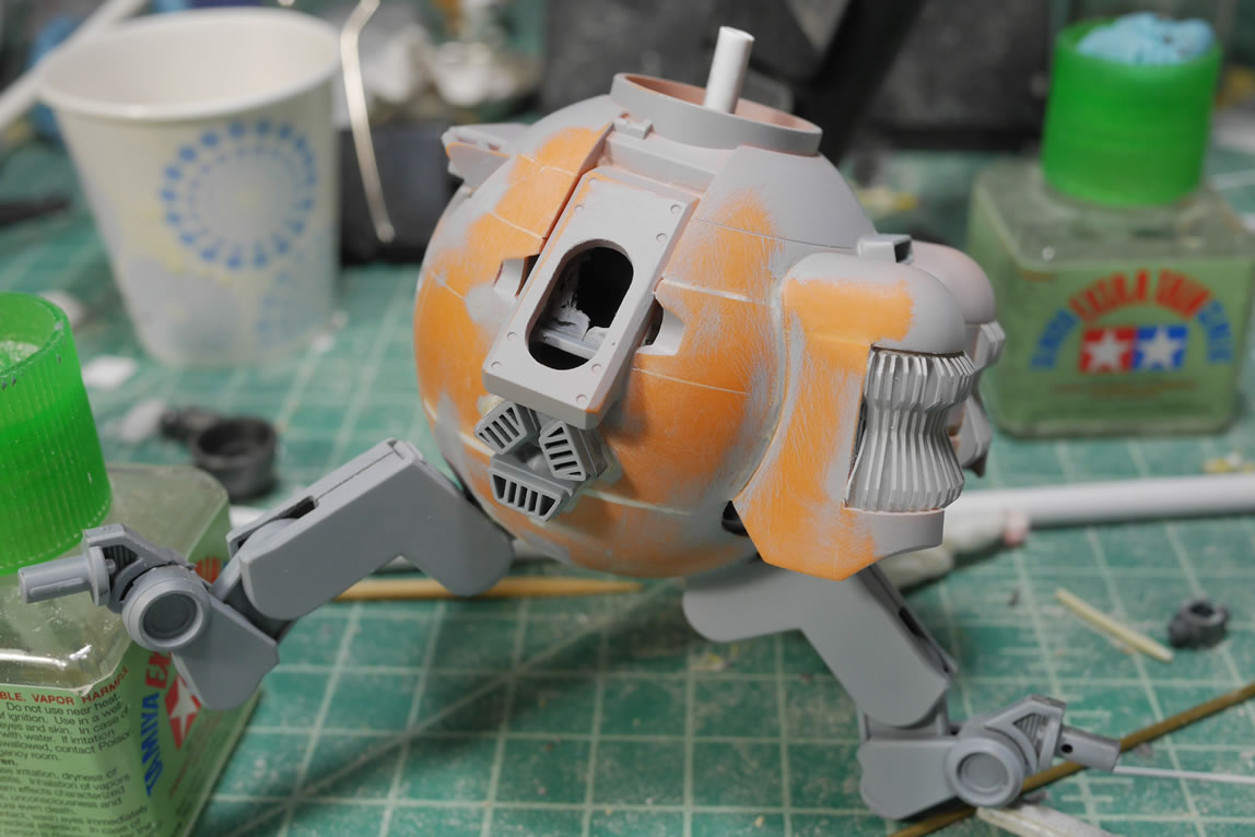
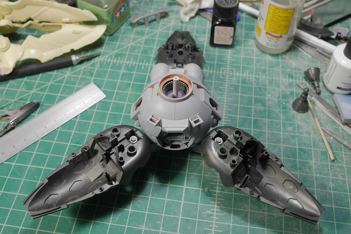
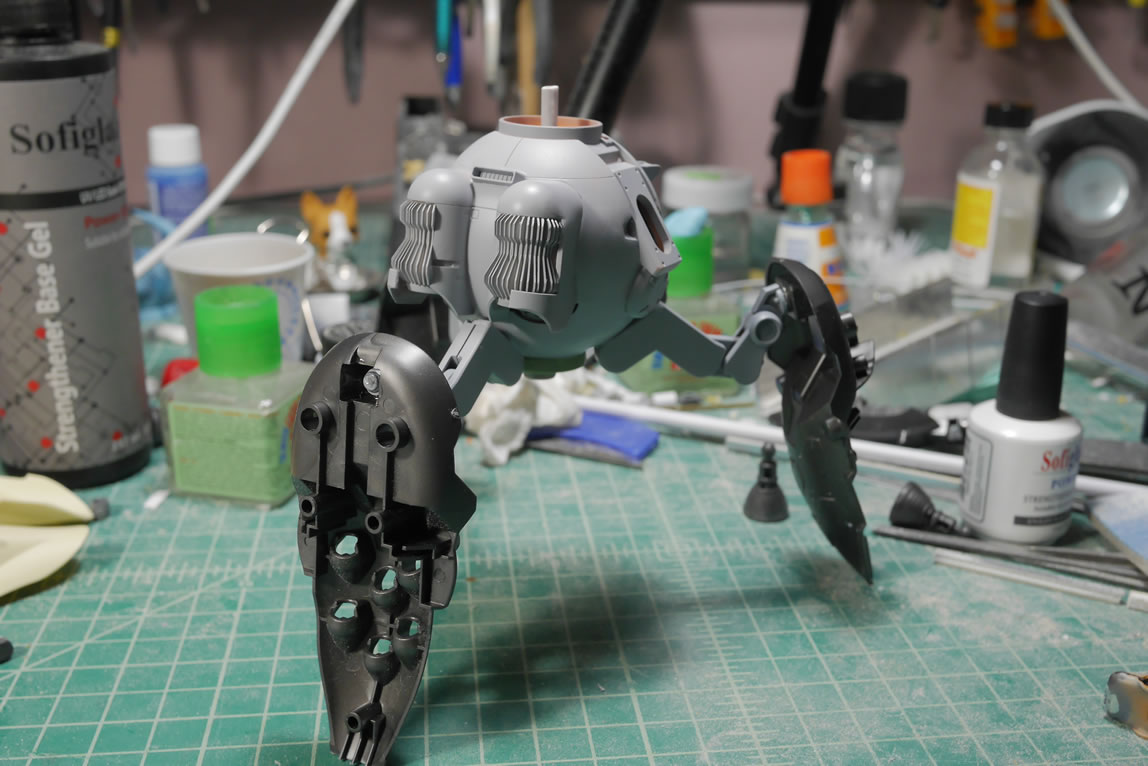
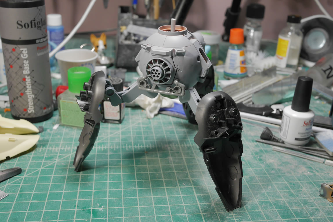
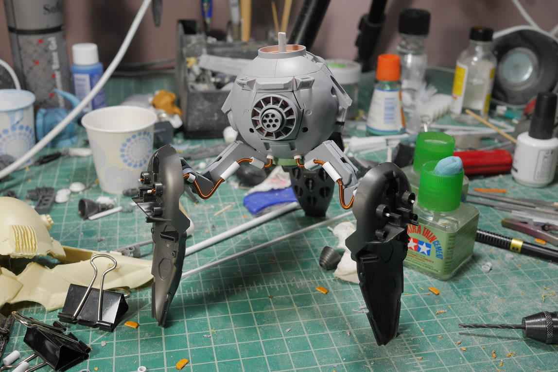
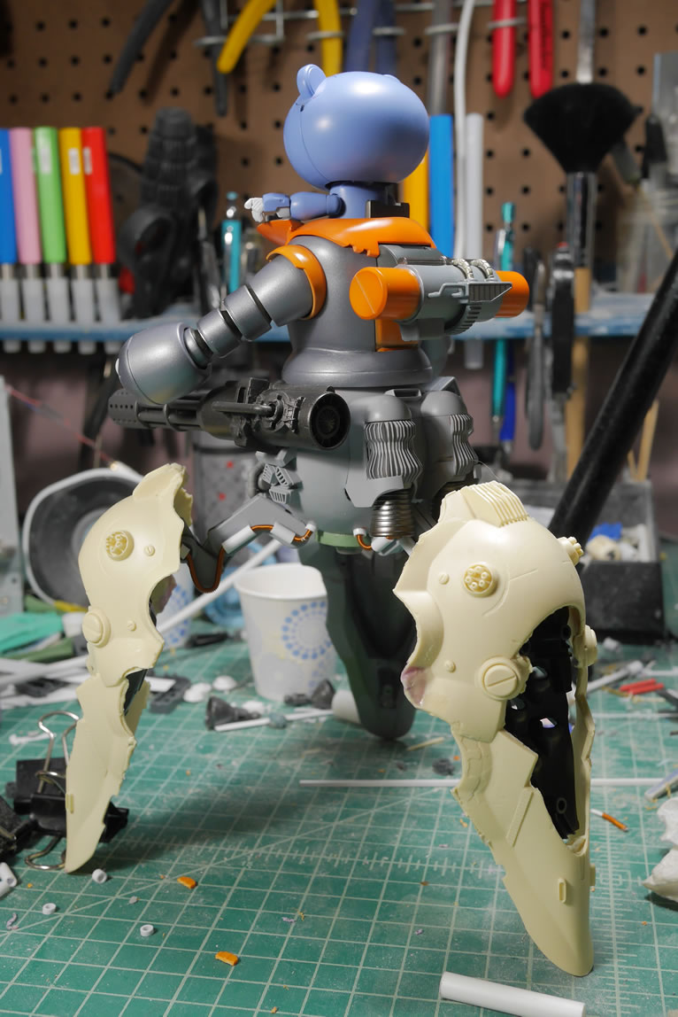
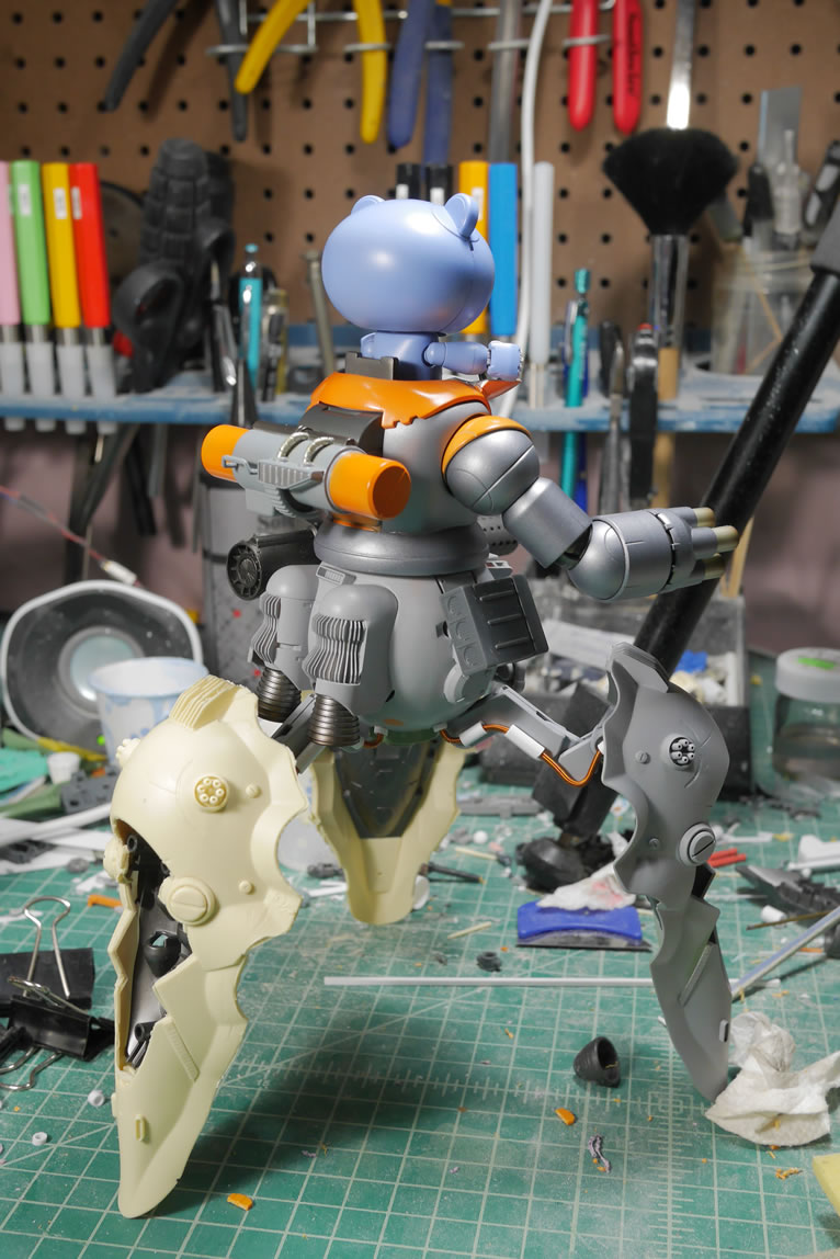
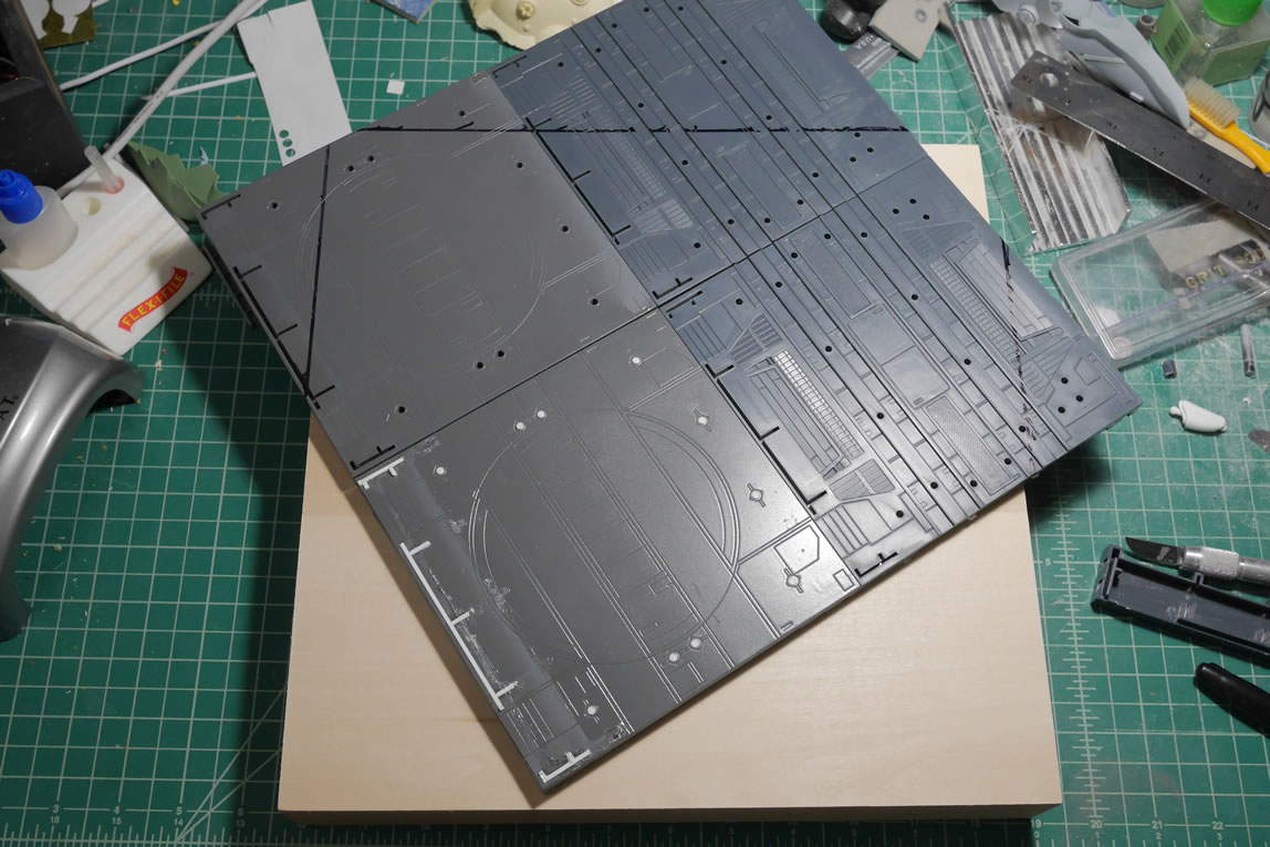
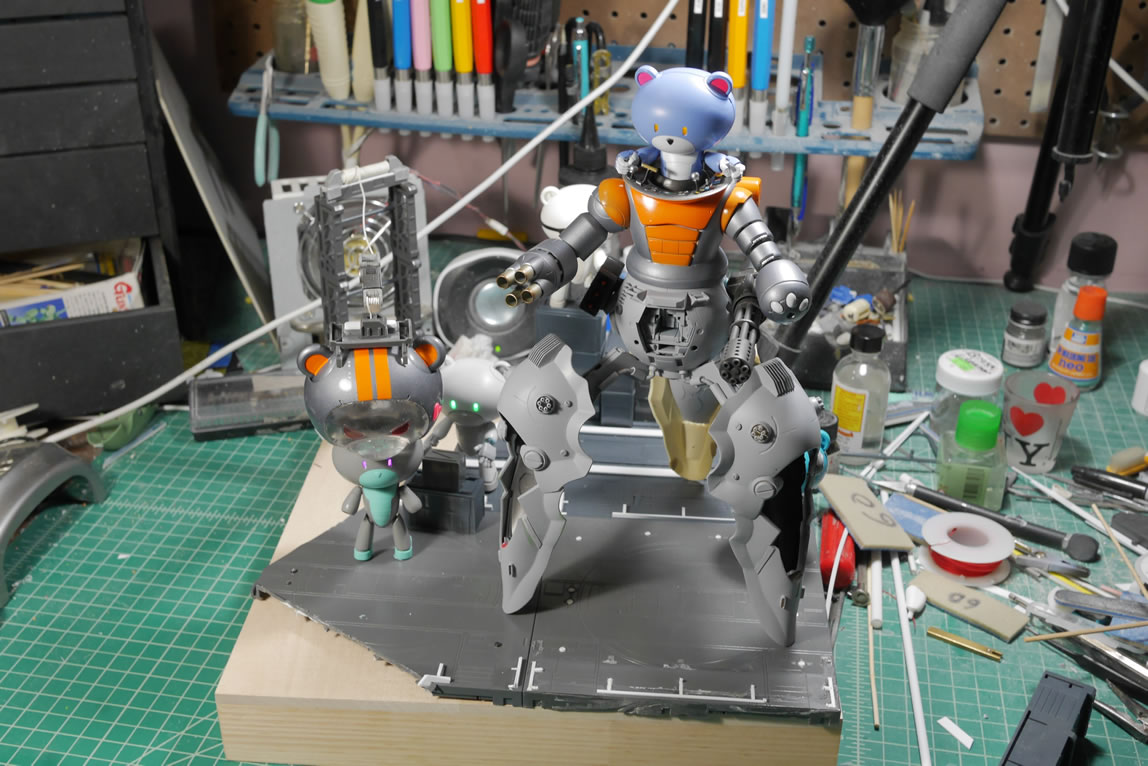
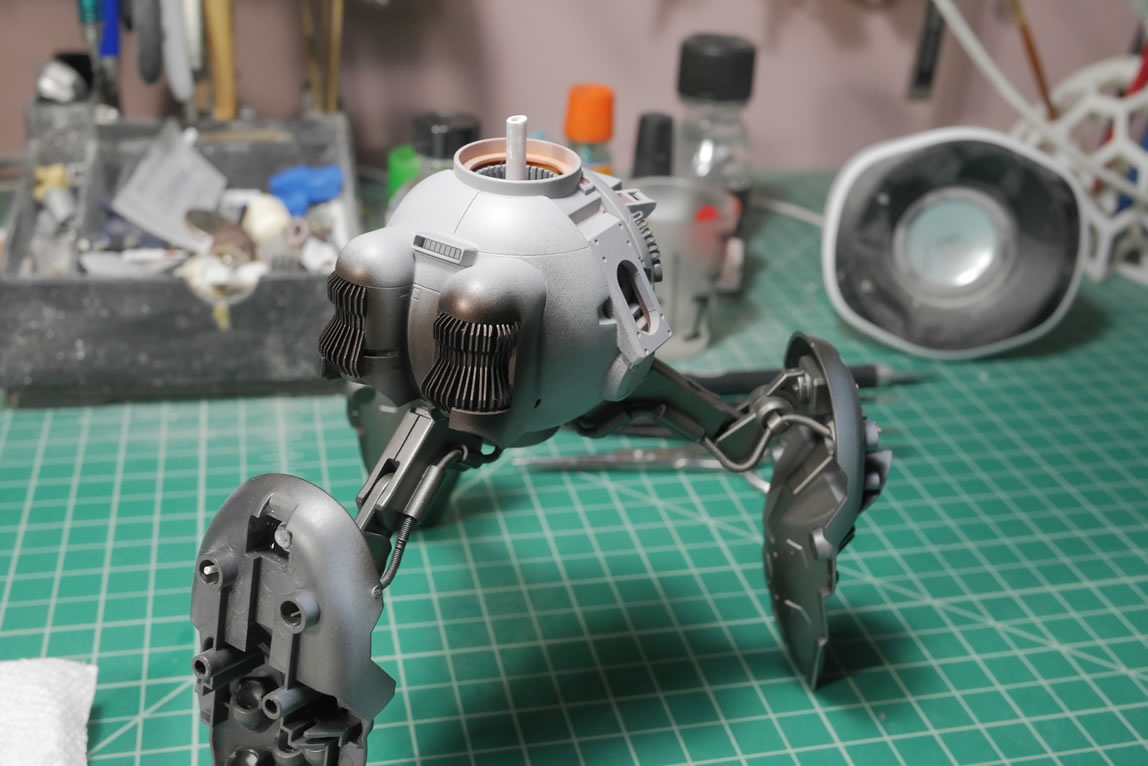
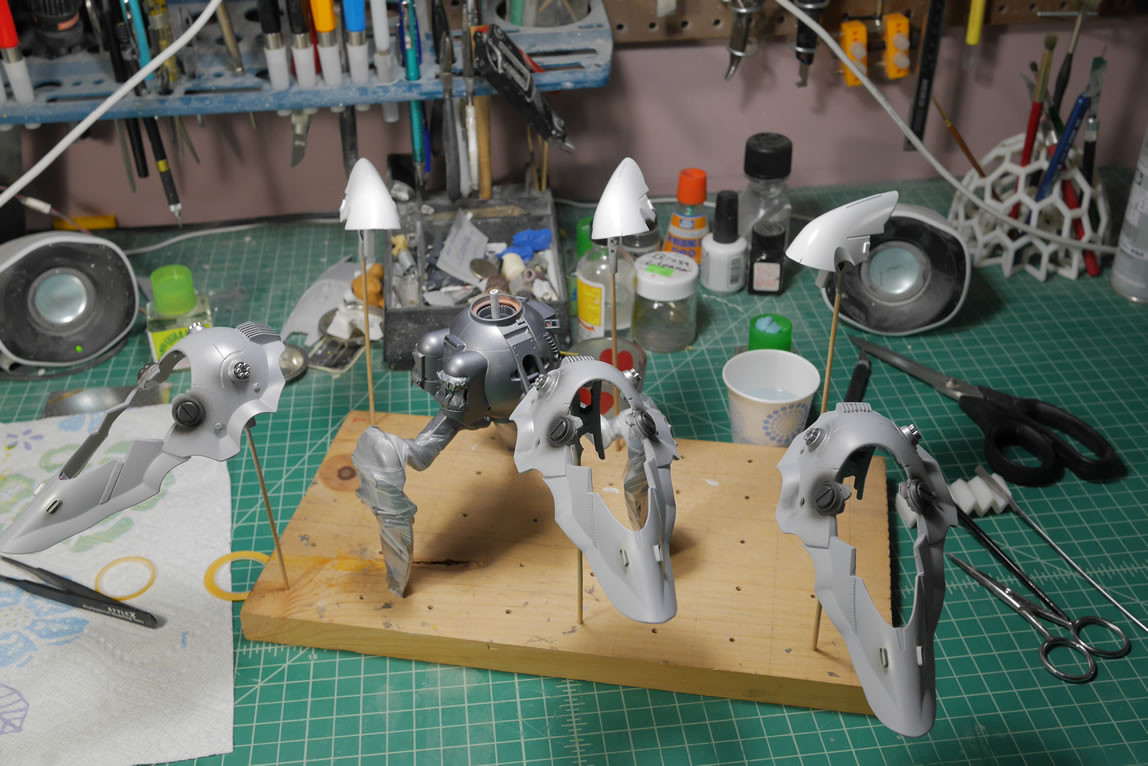
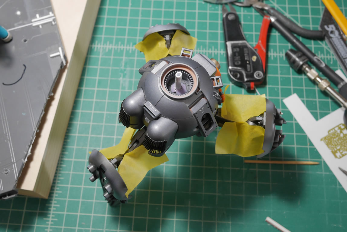
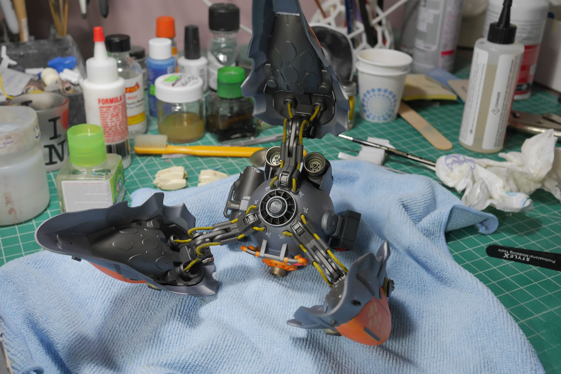
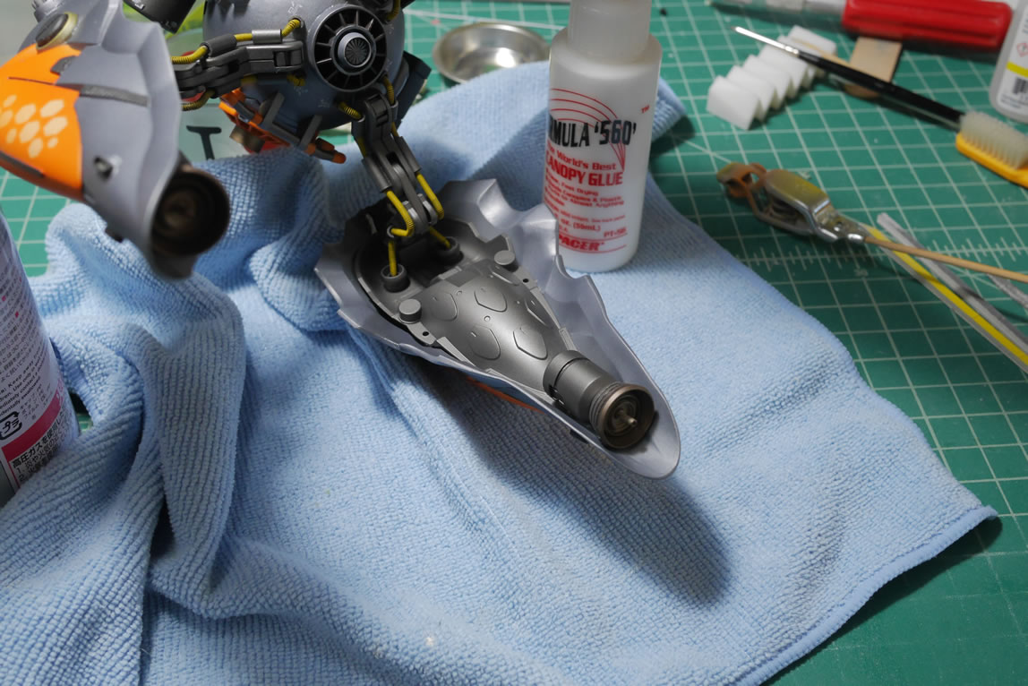
The legs done, I can finally do a real mock up of my project. The first thing I need to do is to glue in the connecting joint pieces to the bottom (actual top of the kit) of the Ball. Reason I used this orientation is that the bottom of the MG Ball works as a perfect connection joint to the BG torso. The top of the Ball works very well because it’s got holes and a structure I can use for the binder’s connecting joints. Those are glued into place and left to set.
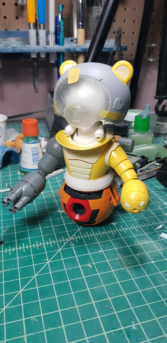
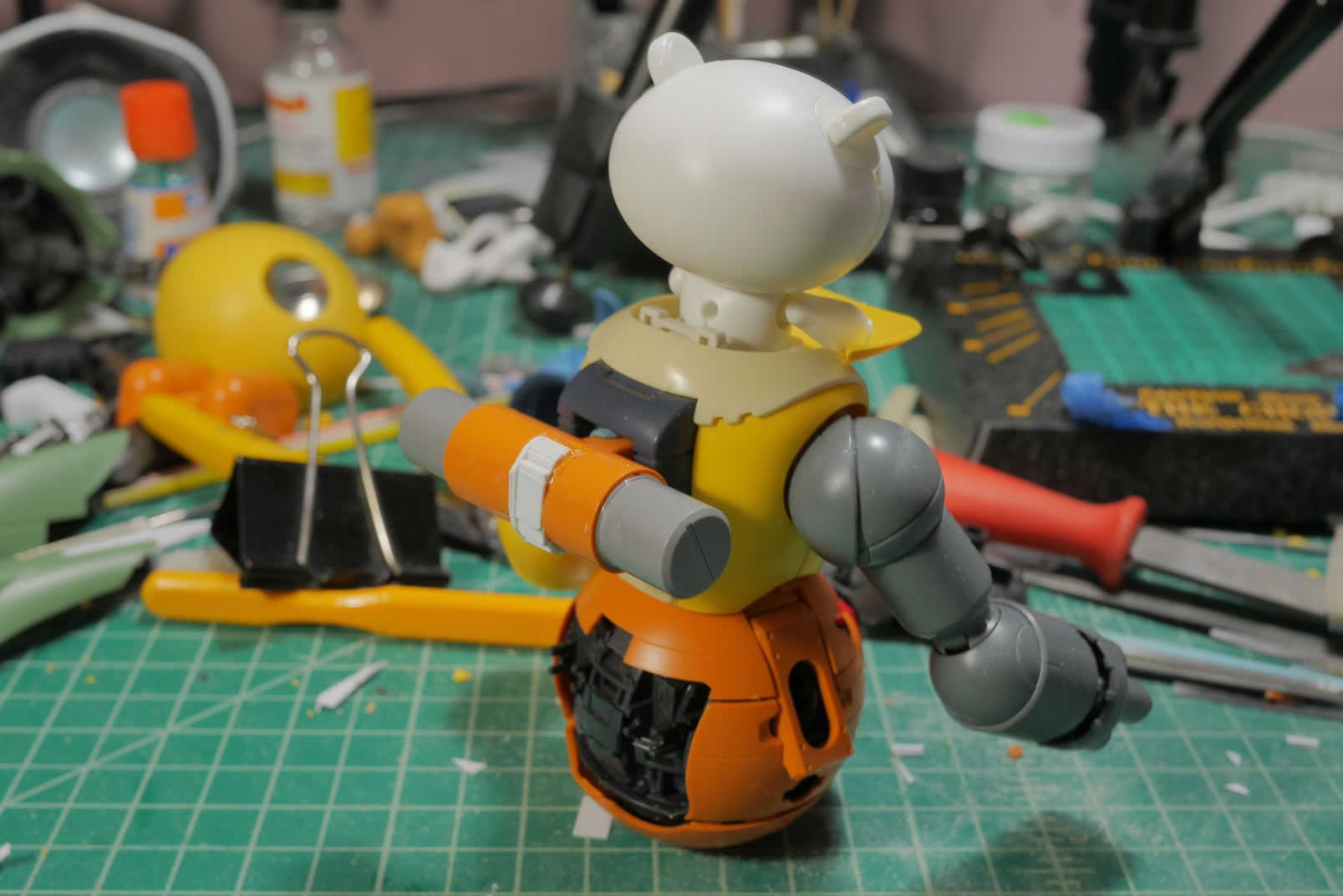
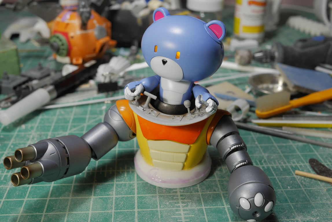
Once the connecting joints are set, I plug in the legs and my BG has legs. I finally have a more realistic mockup of the project design a month into building.
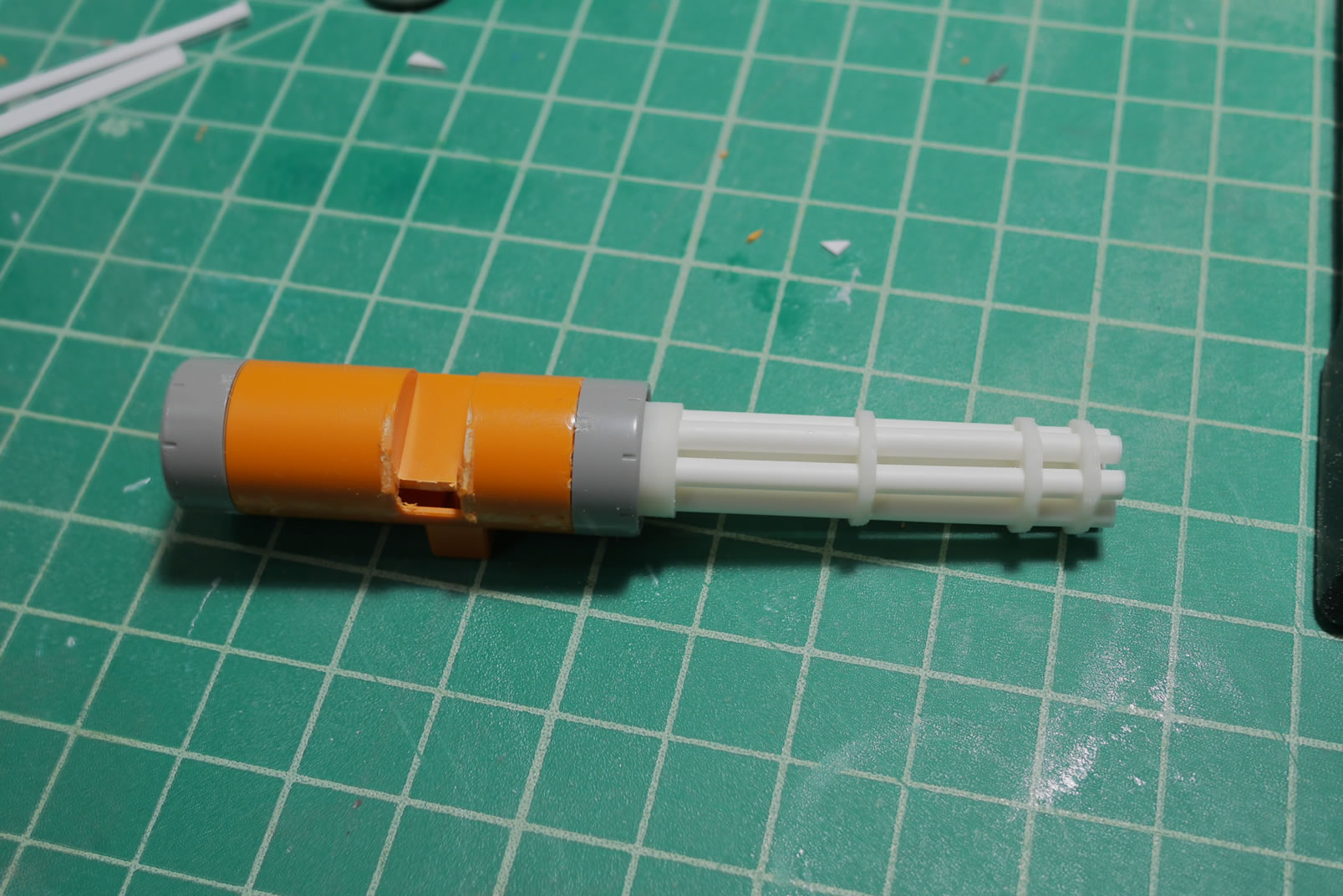
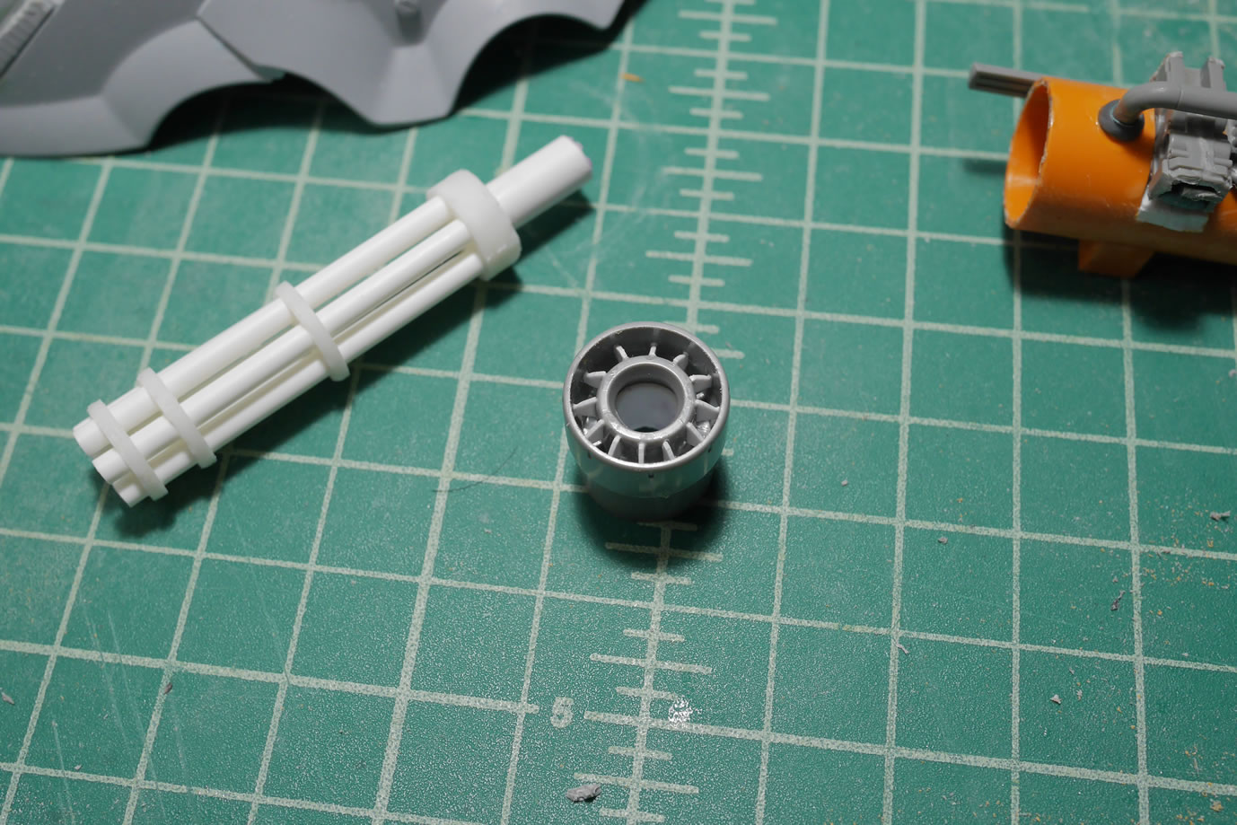
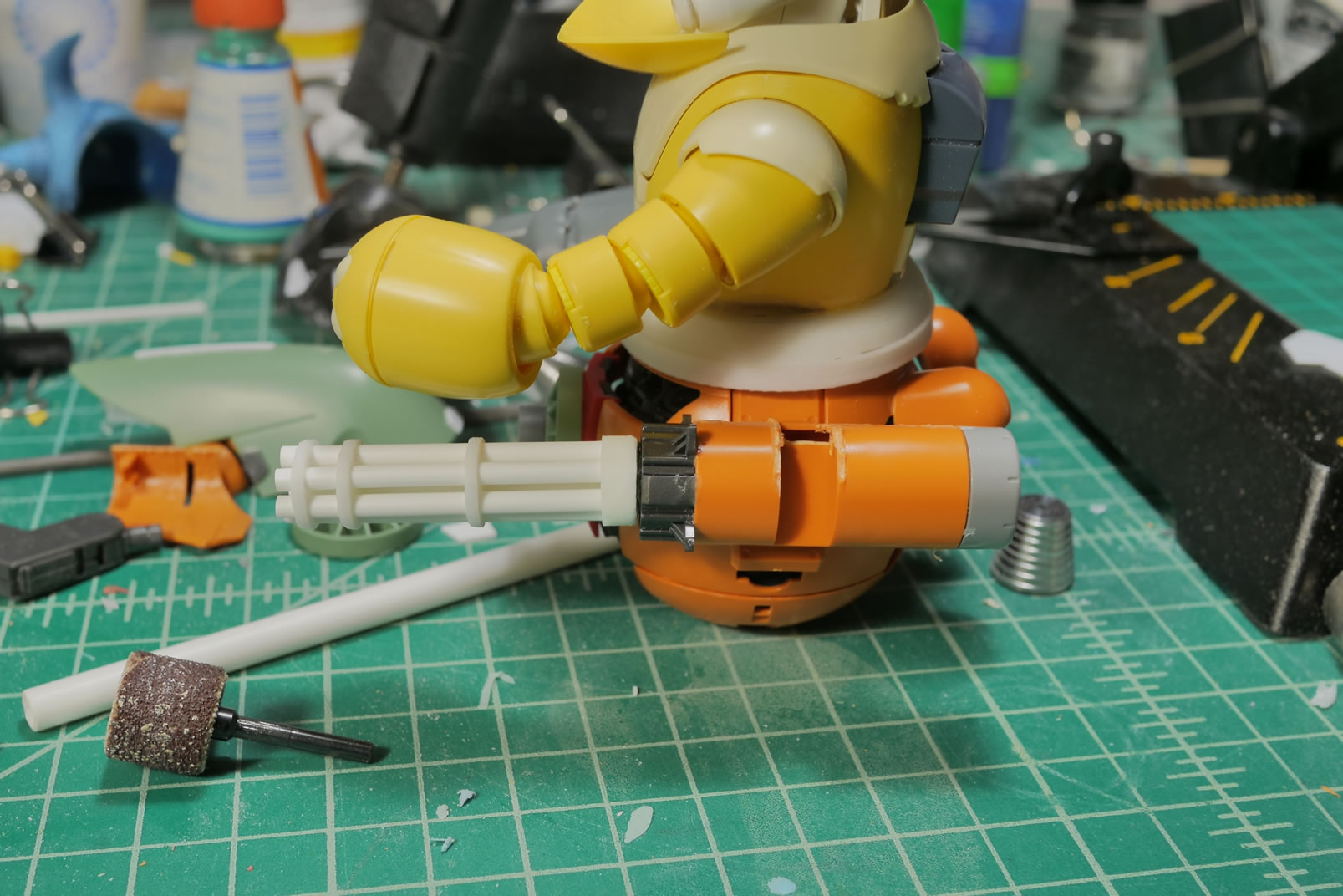
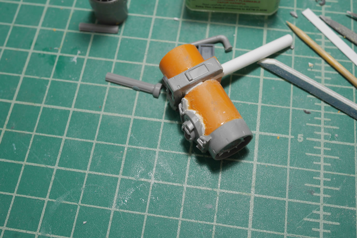
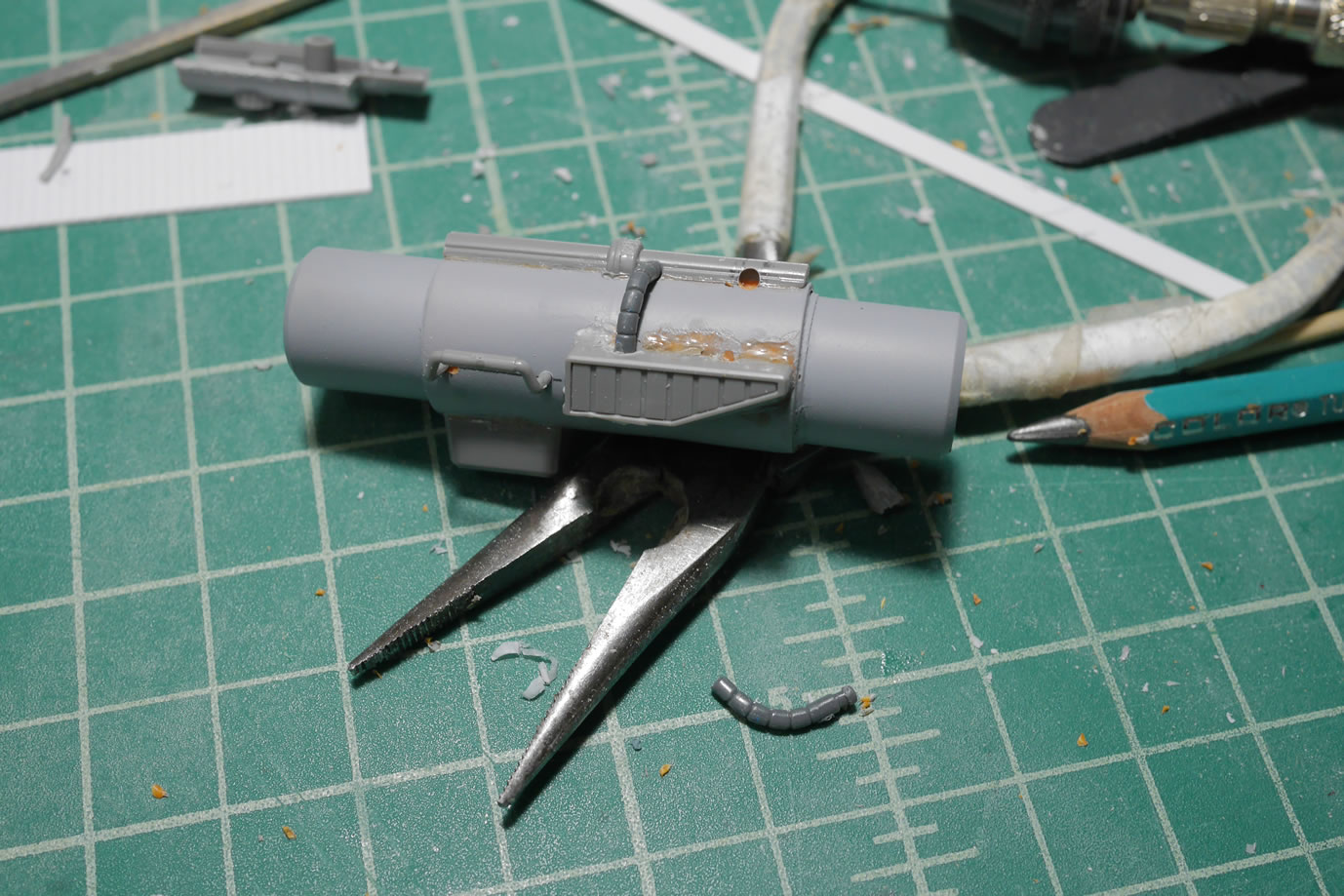
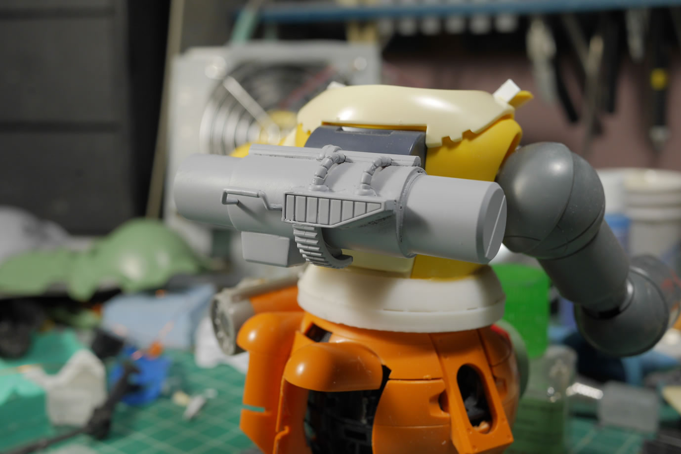
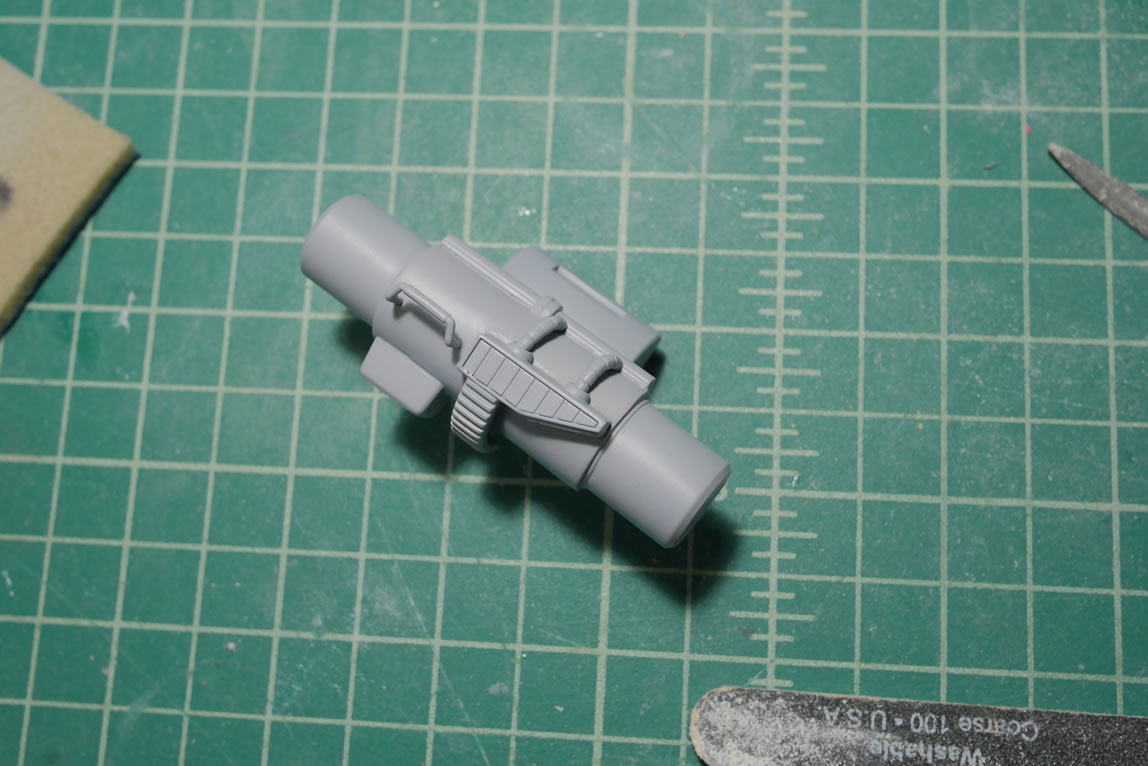
I need a break for working on the binder/legs and I did not want to spend the rest of the weekend cleaning up and fixing the resin. Time to build another gatling gun. Using some styrene tubes, some 3D printed frames from when I built the Gusion’s Gat, and one of the Ball’s main arm pod assembly pieces; I start to put together a rough weapon. The front and back of the gat body is capped off with more bits from the Ball. I cut some plastic pieces and glued them inside the space between the two circular areas on this part. Originally, a rubber piece fits into here and the rest of the Ball’s arms body extends from here. The pieces of styrene work to make the part look more like a turbine. The center of the part needs some details so Again, I have some choices. One side is for the back end of the weapon’s body and the other side is where the barrel connects.
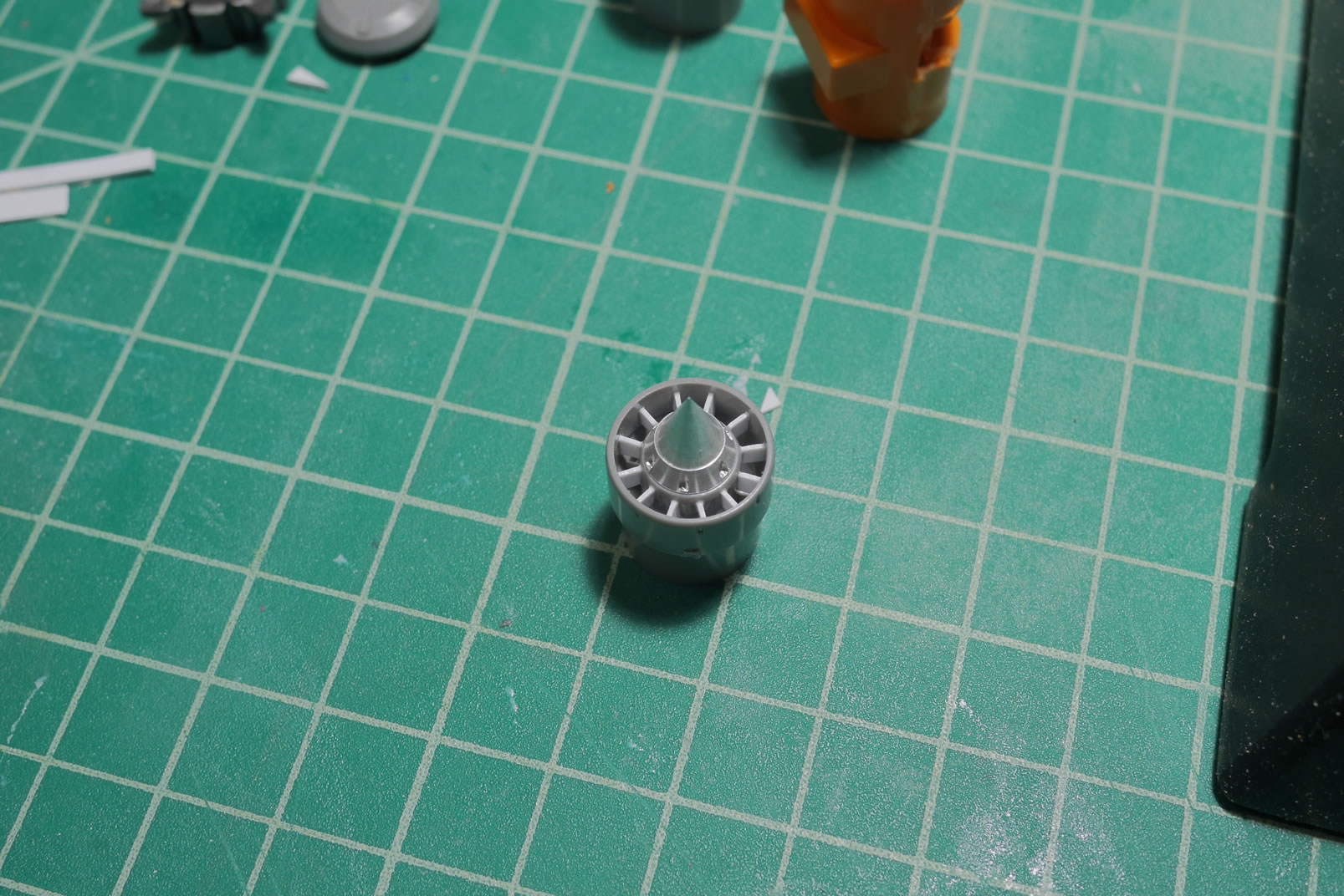
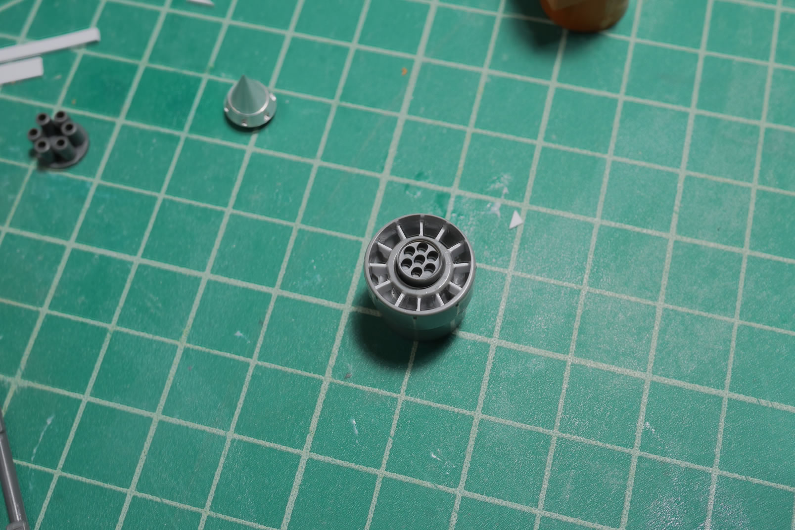
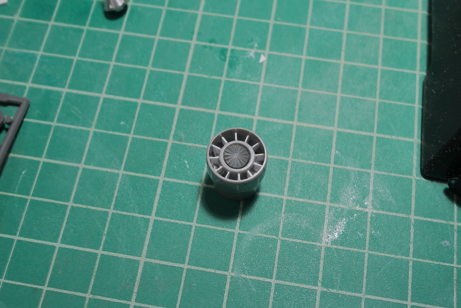
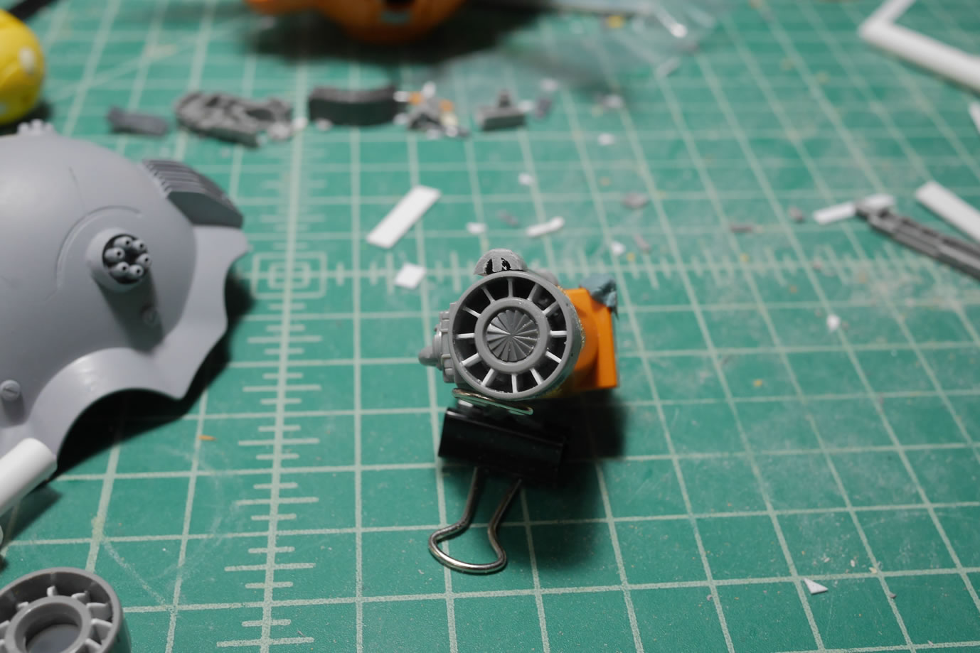
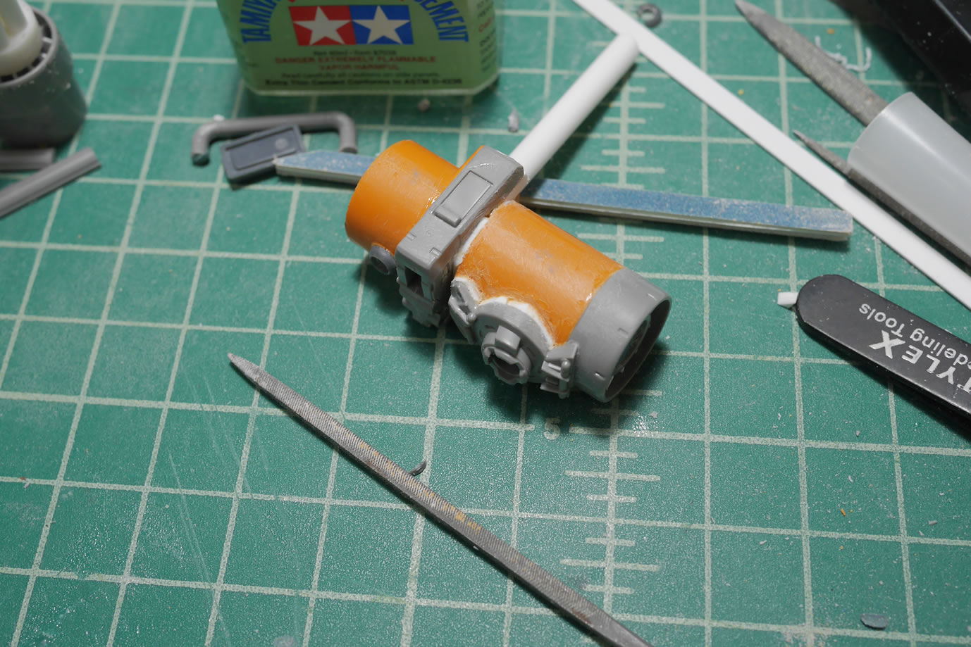
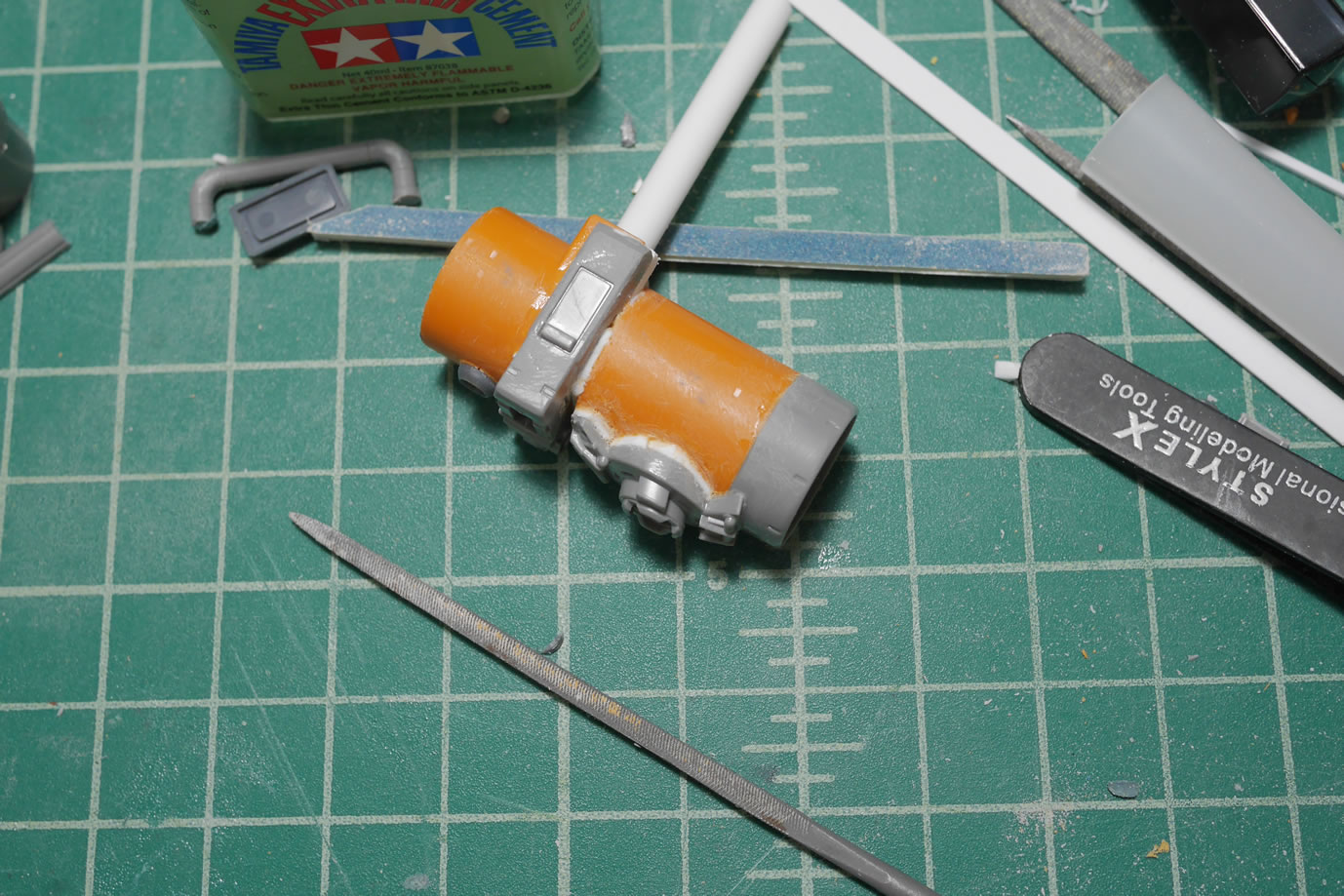
This time, for the back of the weapon, I picked the turbine detail as it goes very well with the outer turbine look.
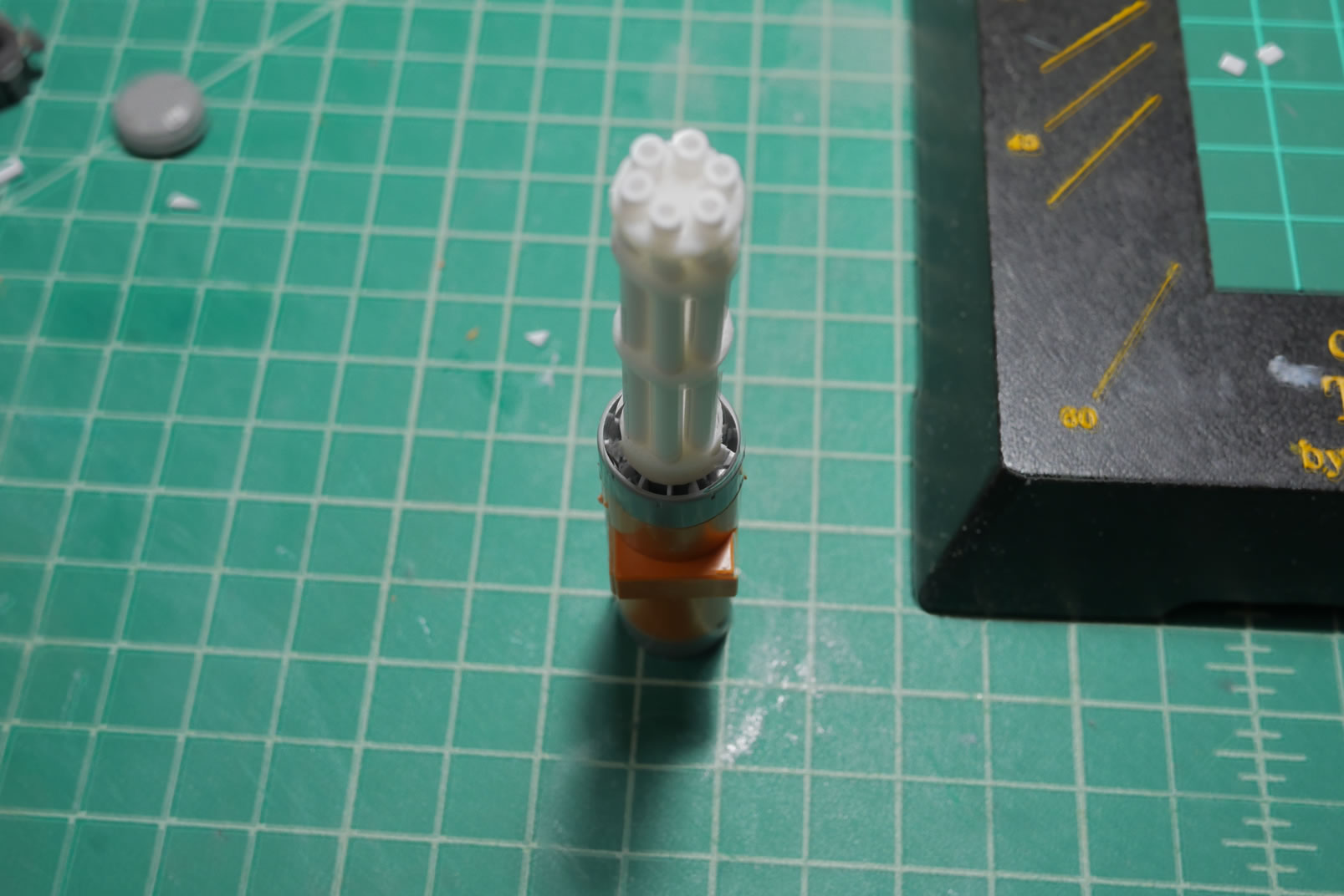
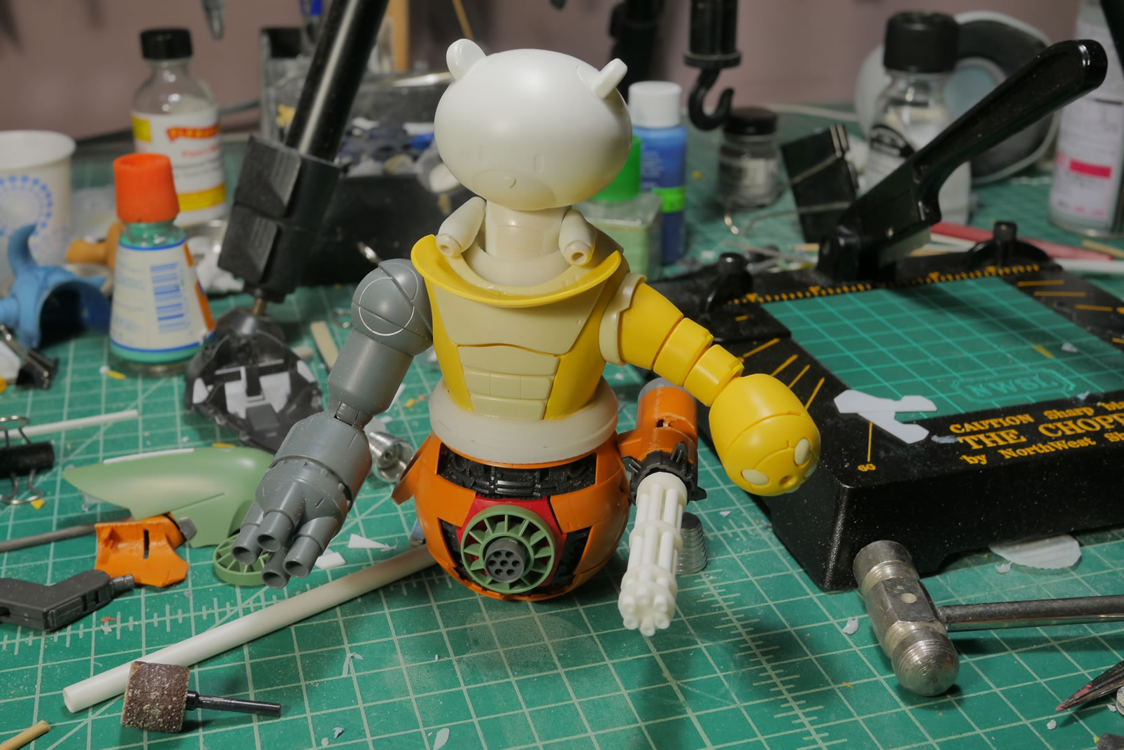
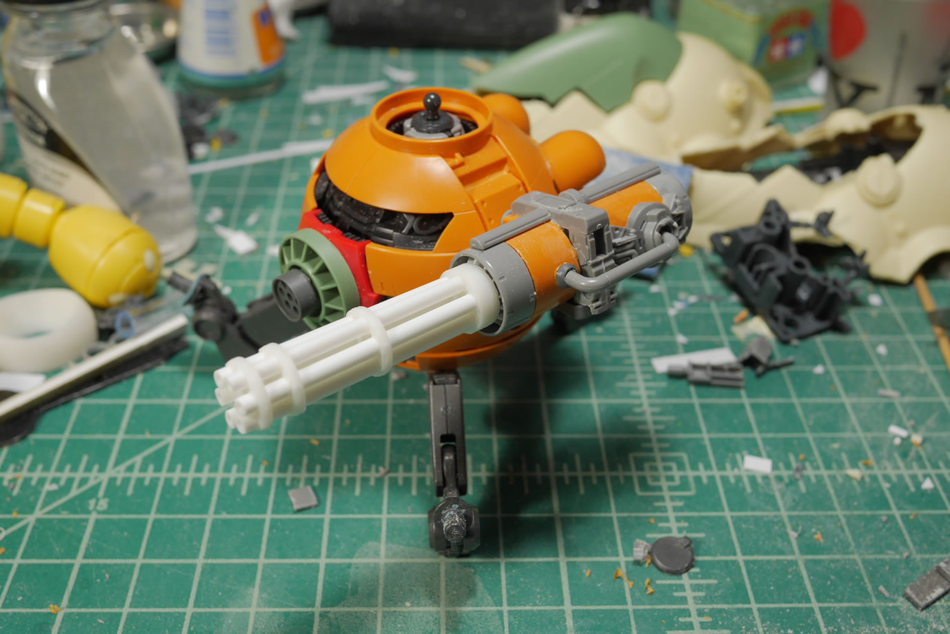
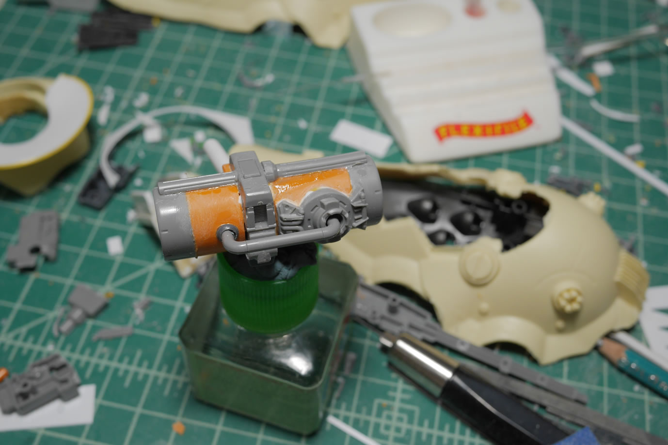
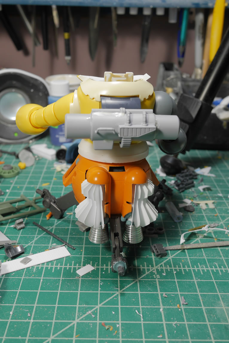
Here are some quick mock ups of the base weapon and how it fits in the grand scheme of the BG. Side cannon so to speak.
The cannon is fairly plain so time to start looking for detail bits. The Ball has some amazing detailing in all areas of the kit. So it’s easy to find something and just cut it up and use it all over the place. This version of the Ball has the twin cannons as well as the main cannon. I used one of the twin cannons and just cut it up and used sticky tack to get a general look and feel for things. The side piece of the ball where there’s a detail clear piece is glued in here as one of the main detail bits. One of the tube bars from the Ball kit fits perfectly coming out of the side part and just adding a wave circle detail completes the look. The engine detailing on the twin cannons is also cut up and added as engine details for the gat body too, running perpendicular to the Ball’s side bit. A small venier at the bottom completes the mockup.
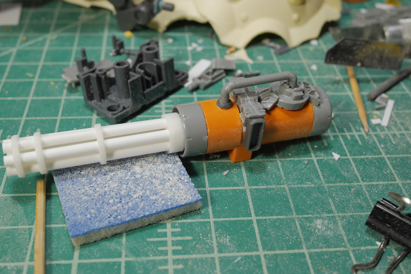
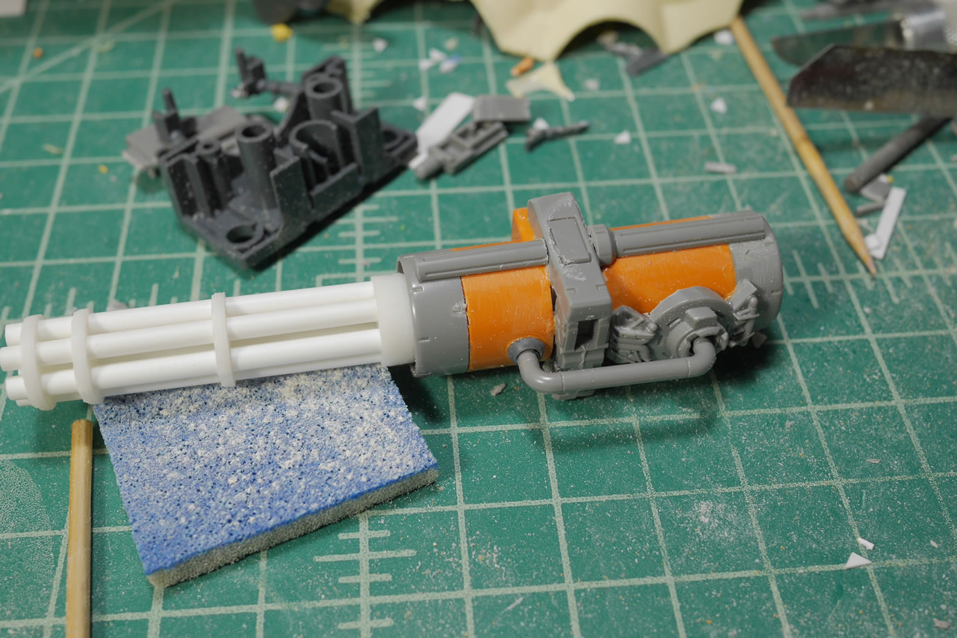
With everything mocked and approved, we go to gluing and filling. There is an awful amount of filling that happens in kitbashing. Styrene is your best friend. Glue melts and welds the pieces into place. Once set, a quick sand to rough up and shape the gap areas to prepare the surface for some putty work. After the excess putty is cured and sanded.
The initial surface prep is complete and it’s ready for the first layer if primer.
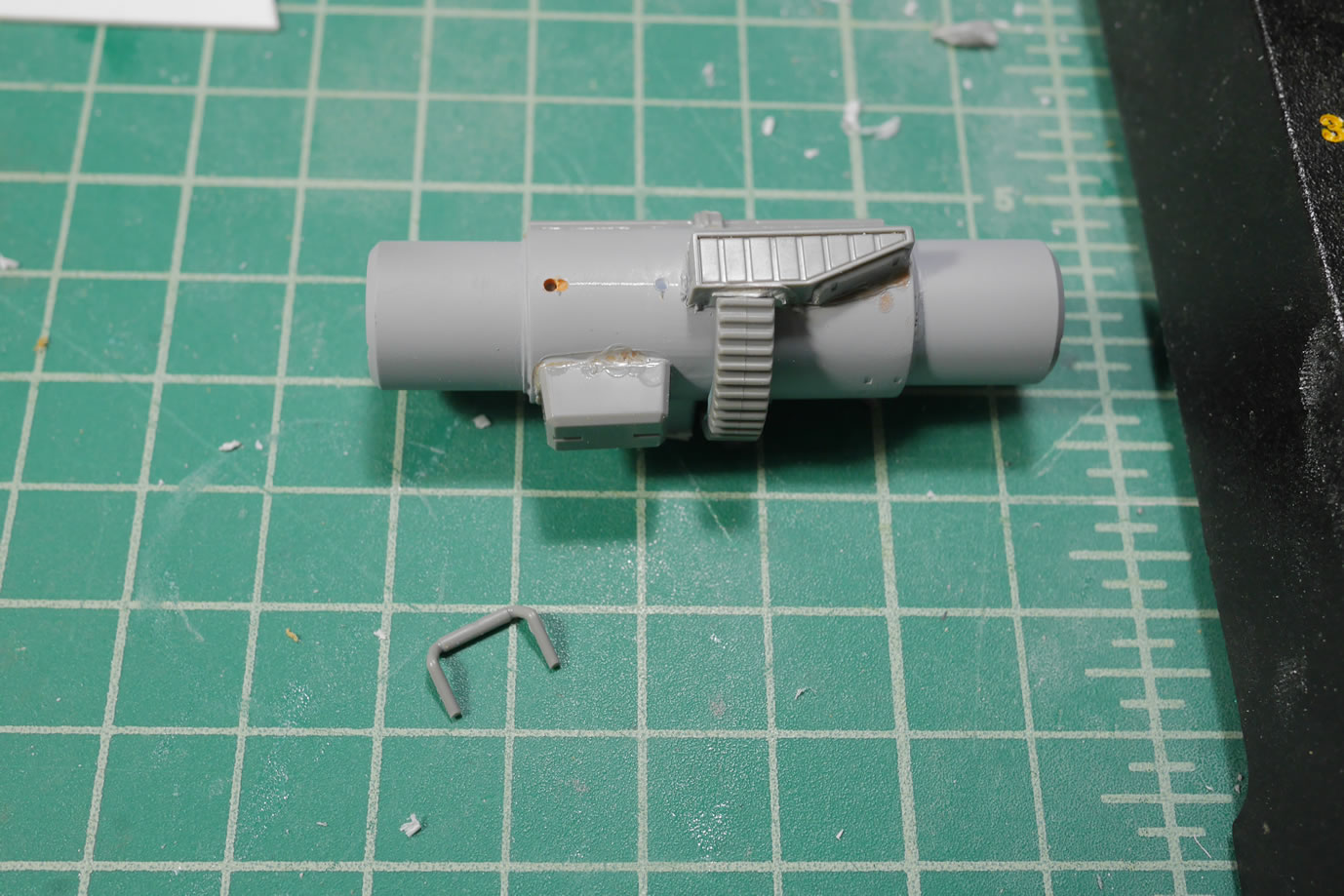
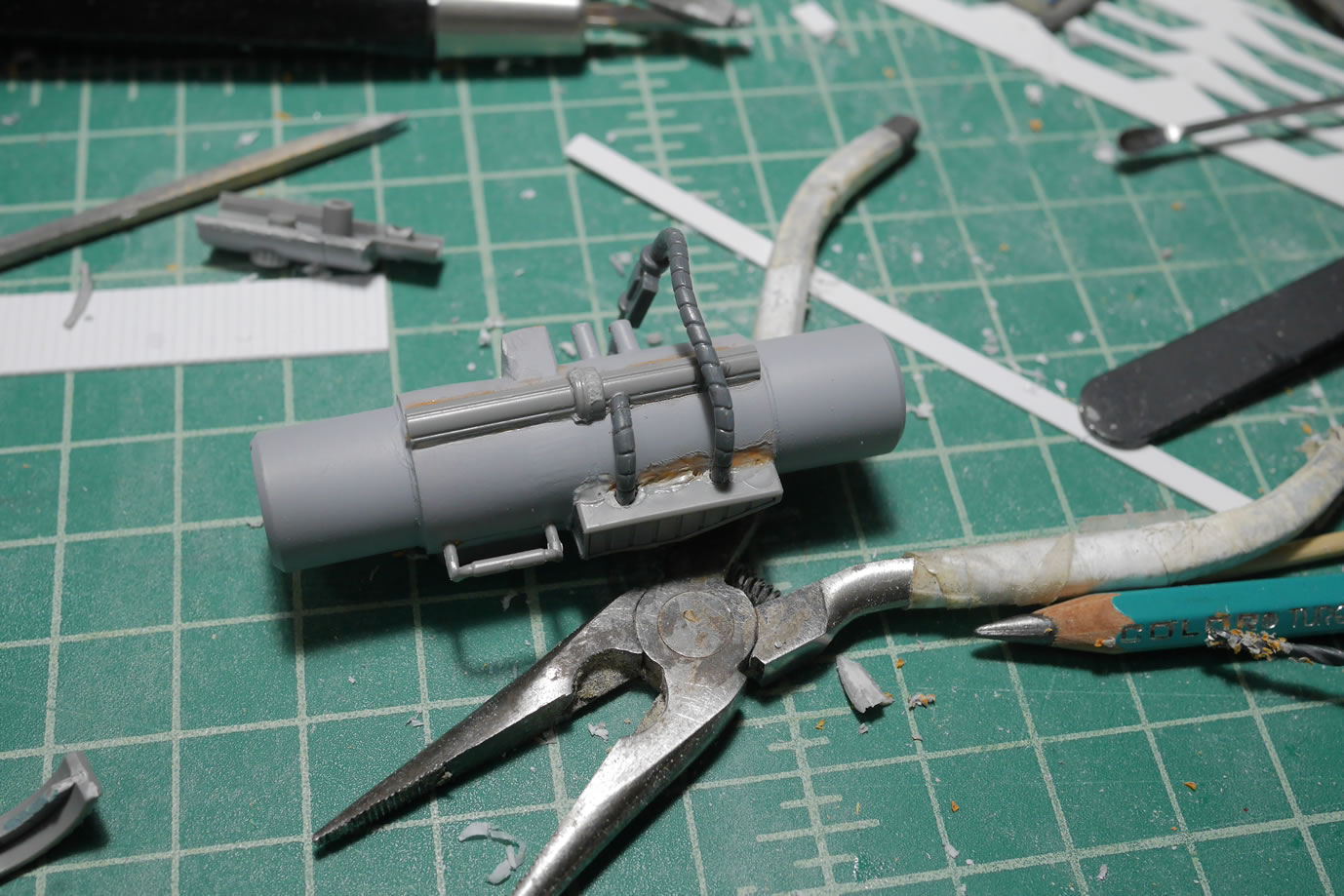
Next up, the fuel tank. The other side of the Ball’s arm pod doesn’t go to waste. Here I quickly put together a fuel tank and filled in the rectangular cavity with stacks of styrene strips and then sanded it down. The two ends of the Ball’s arm bits are used as the two ends for the fuel tank. But just like the gatling gun body, it’s boring in this current state.
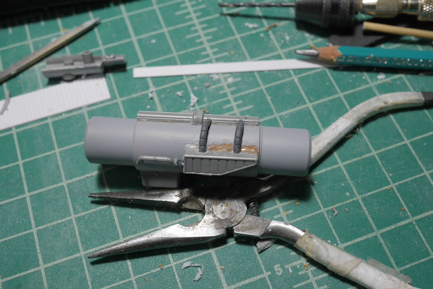
Cutting up more bits and pieces from the Ball kit, I start adding details here and there. The gear detail from the big cannon on the original Ball is cut and used here. A small tube detail is added by drawing out some straight lines and making the right measurements and a few drilled out holes and the tube detail is inserted. One of the pieces has two male pegs that I cut off so there were some holes to fill. Instead of filling, I found some left over Zaku/Gouf head cables and trimmed them up and added them as connection tube details between the top piece of Ball twin cannon gun barrel haves and the bottom vent detail with the peg holes.
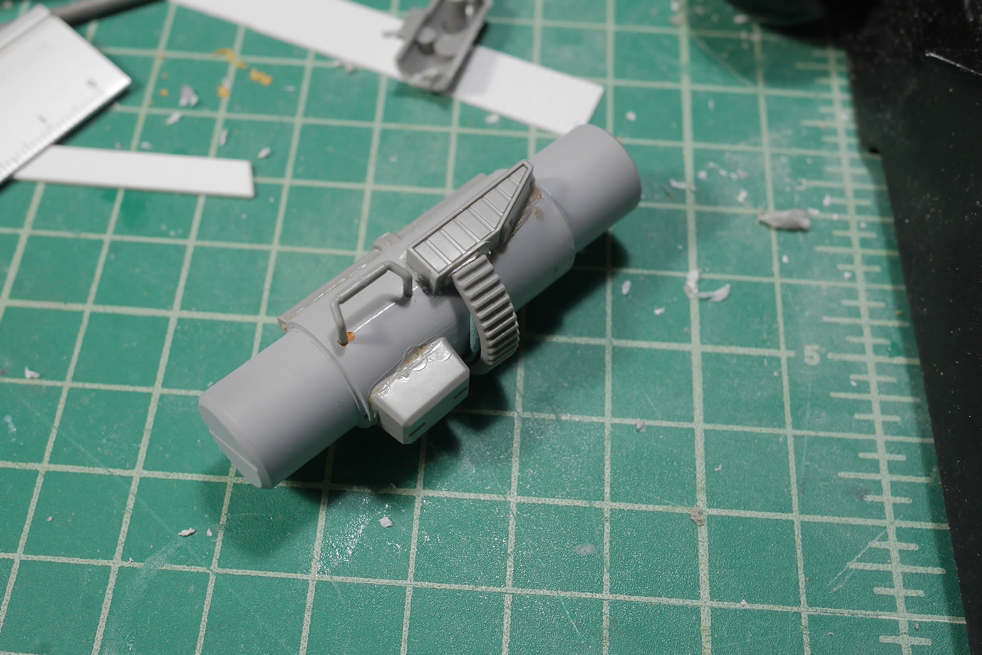
As glue to the add on pieces dry, the areas are sanded and more details are added so that there is a bit of transition between some of the added details. The tubes just sticking out of the middle vent piece just doesn’t make much sense, so some koto round detail bits are drilled out and added into the area as a transition piece. Once all the initial sanding is done, another layer of primer is sprayed to check for flaws. There are definitely flaws, and the primer really shows the problem areas nicely. So next up will be more clean up work, but the build for the fuel tank is done.
Small details here and there to further dissociate this from being an MG Ball. It will still definitely look like a lower MG Ball torso, but hopefully the details will help transform this more. I found some round bits from the Kshatriya so another koto gat detail piece is added here.
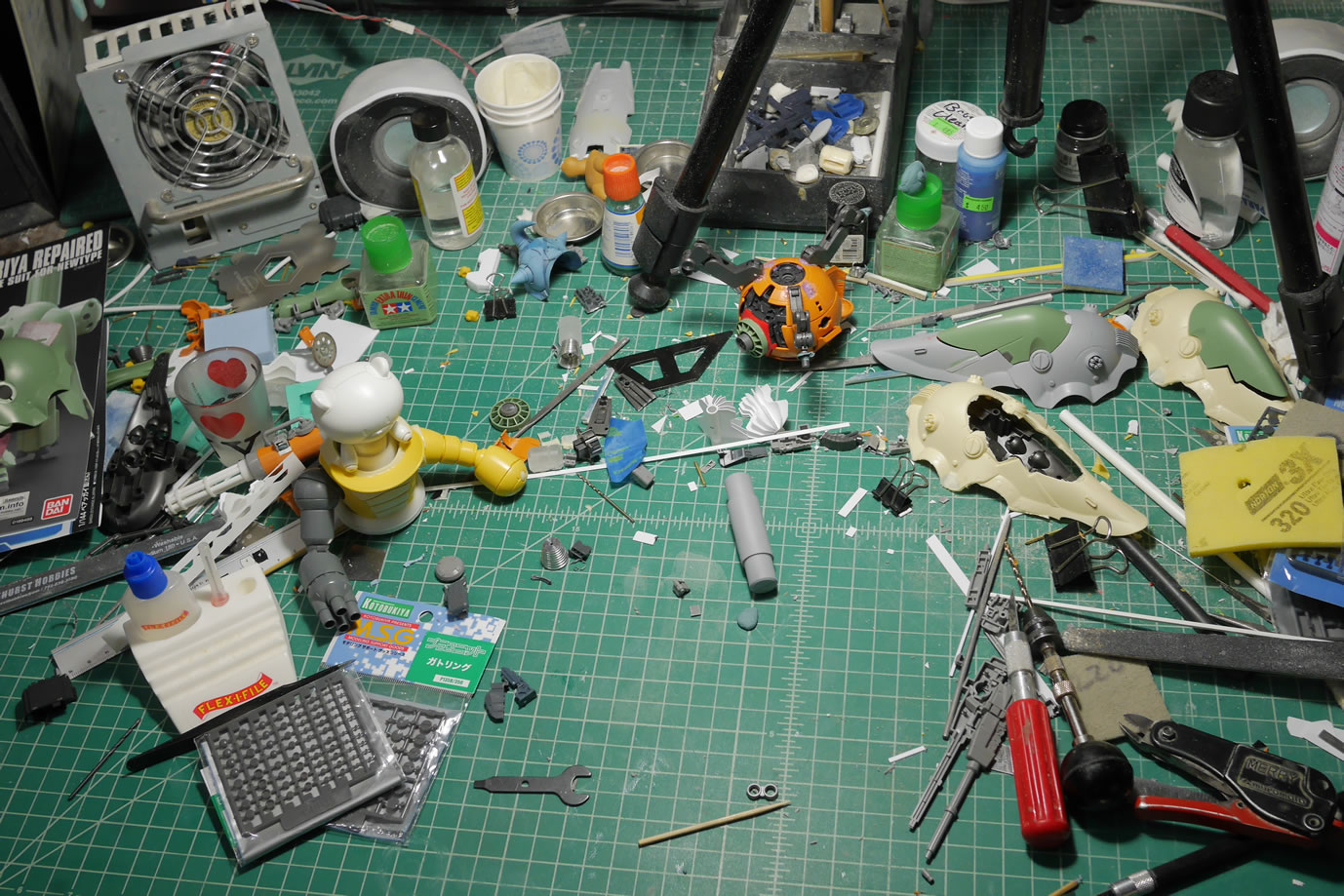
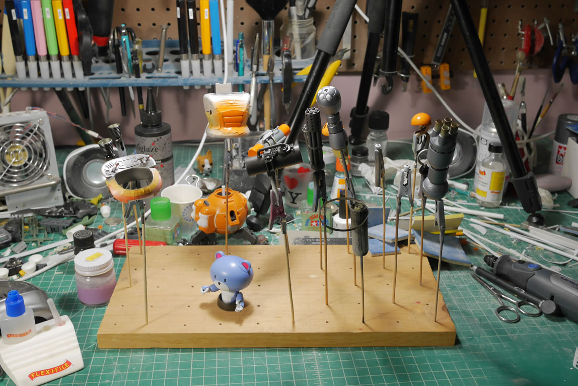
The workshop is a mess but I’m having a pretty damn good time building gunpla. It’s been a while since I wasn’t inspired to do anything since SCGMC. Hell, the MG Hazel is still only about 95% done since the shields I made are still in various stages of paint. It sits with the rest of the half done projects as well as the newest member, Grim-Chica. So hopefully the drive to work on this kit continues to keep it from joining that party of partial builds.
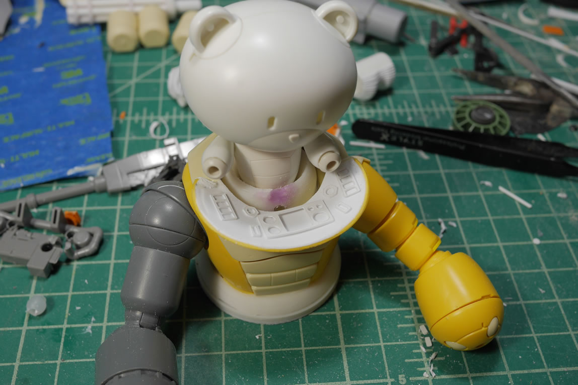
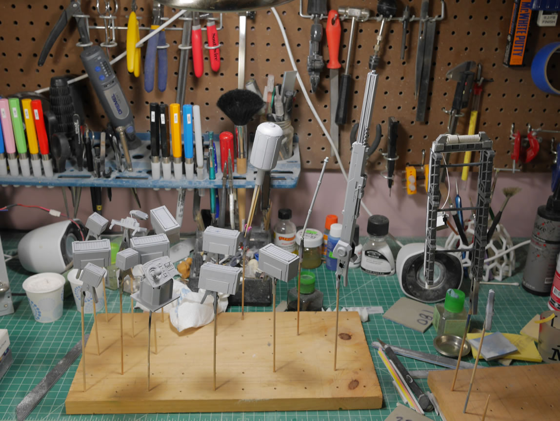
May 31, 2018: Update time. Over the past few weeks, I’ve been steadily working on this project so the little updates I used to do are more meaningful and have more meat to things. I like that I can show more substance than just random in the middle progress that takes a few updates to get the full pictures. It is easier to visualize and to connect the dots so to speak. So let’s get into this. The first thing for this update is filling the 3D printed gatling gun frame pieces. Since the print is small and I’m using the computer controlled hot glue gun style of 3D printer, there are resolution issues with printing so small that there is a bit of clean up. The pink stuff you see in the picture below is just melted ABS plastic in acetone. It works as a liquid ABS putty. If applied thinly, the stuff dries and cures fairly quickly over night so I can get to sanding it down the next morning. In the picture the bottom part has been sanded so you can see small pockets of the purple/pink filler. Once primed, all the defect holes and resolution lines disappear.
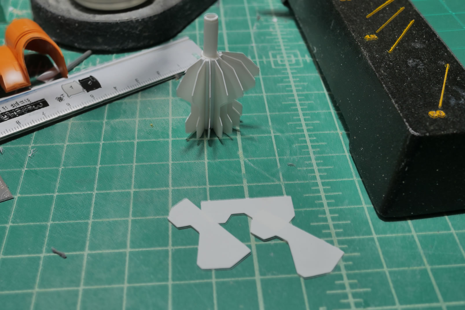
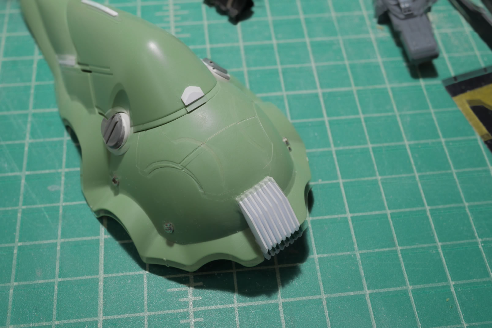
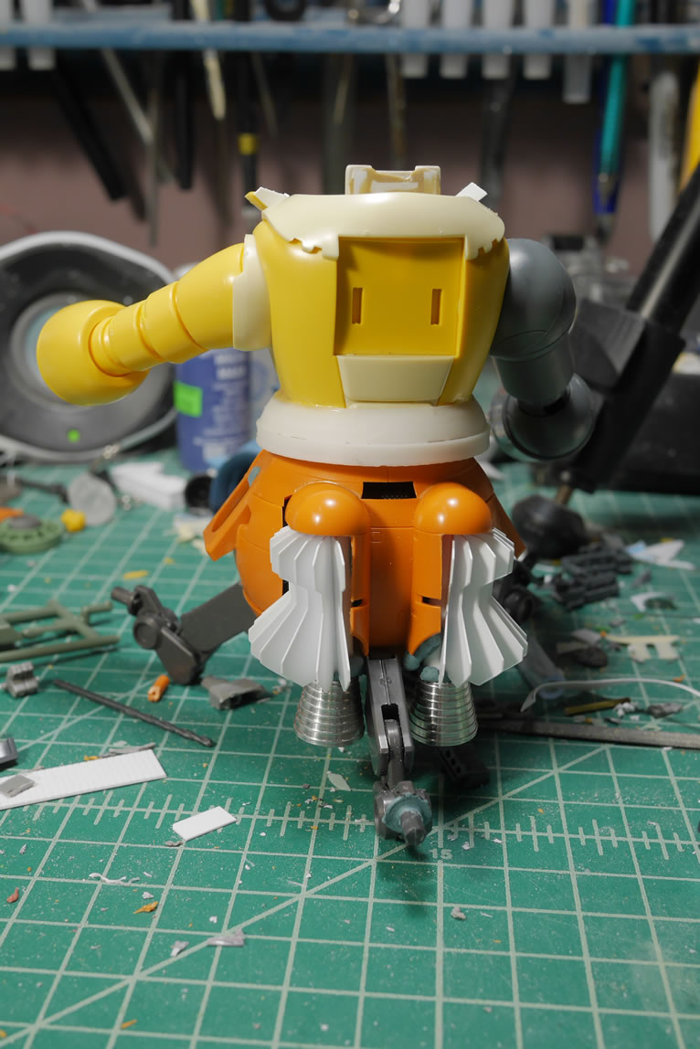
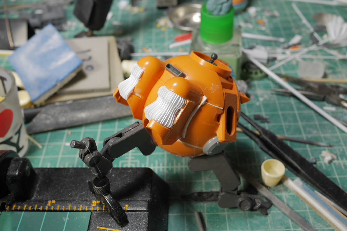
Next up, I did a quick mock up of the vents I built from the die cutting cricut machine. I added in the thrusters at the bottom to get a visual. The backpack is getting primed and still getting cleaned up after modding and bashing that part together; so that is also added to the picture. Mockups work to help me visualize the progress. I have a mental image of the design (I rarely ever draw out my designs and just go from what’s in my head). There is always room for changes as the build progresses. Sometimes, the visual in my mind’s eye isn’t recreated correctly, or if it is, it’s not visually appealing in the real world. So things constantly evolve.
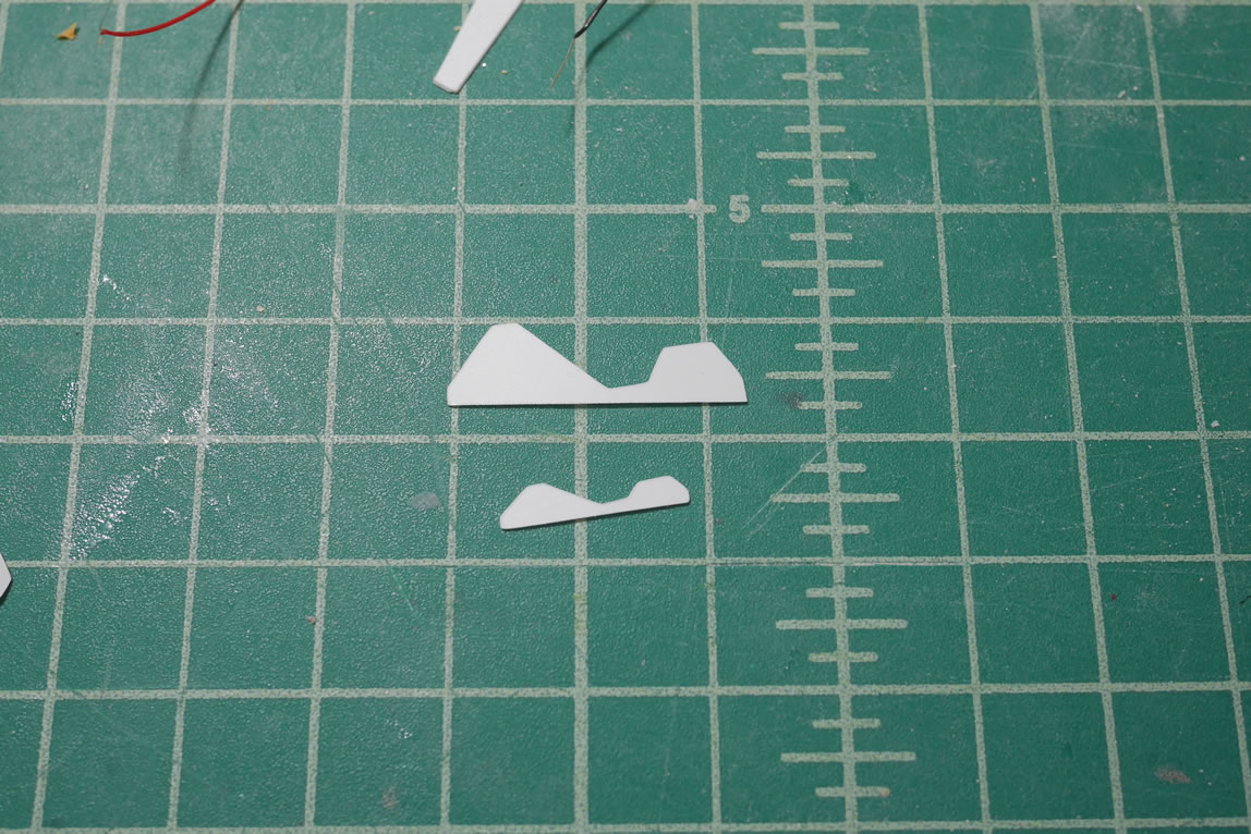
After weeks of looking at the vents, I didn’t care for how they looked; and this was the second time I built them. Time for a third. I went back to the original vent fin designs and made some slight changes. I shrank it and cut a different bottom angle. Once designed, I made copies and had the cricut cut out a .1 mm thick sheet of styrene.
Here’s a live broadcast showing making the new vent:
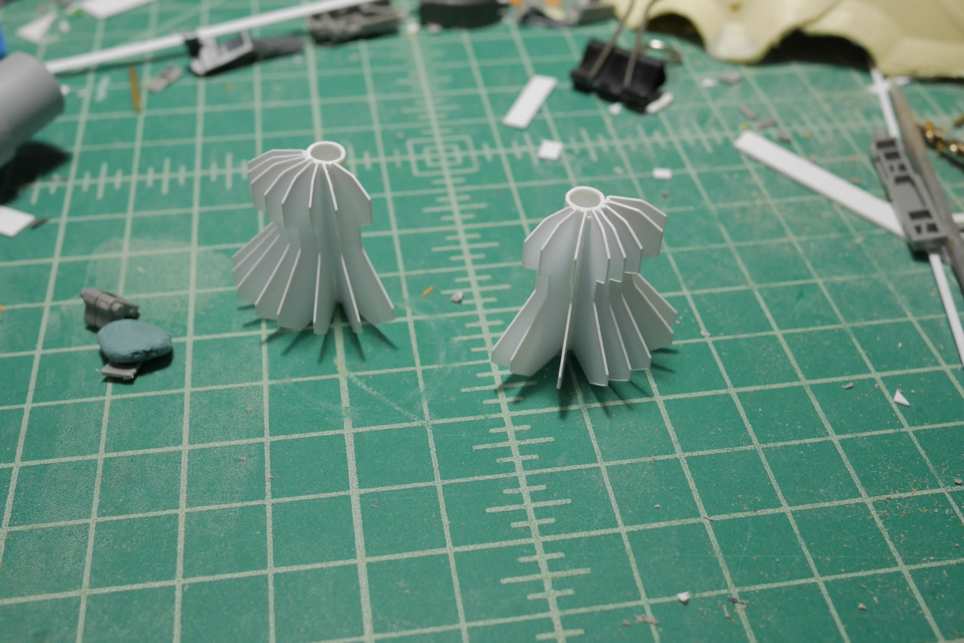
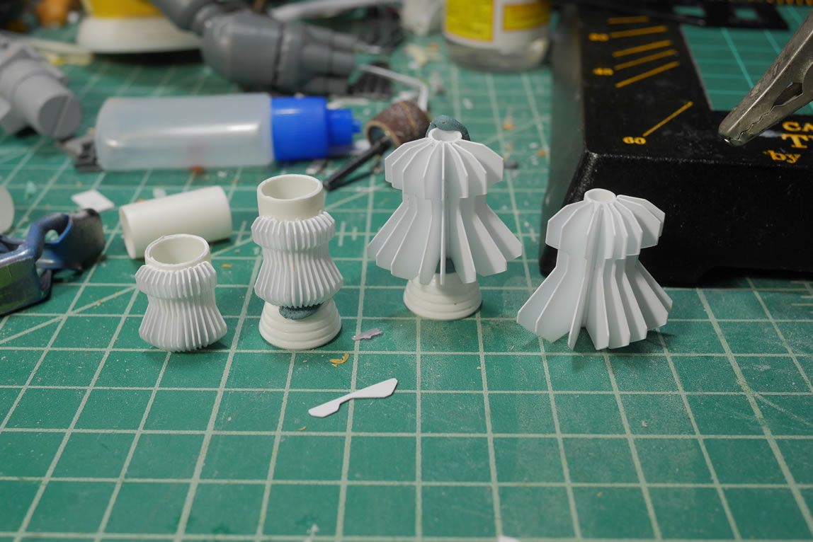
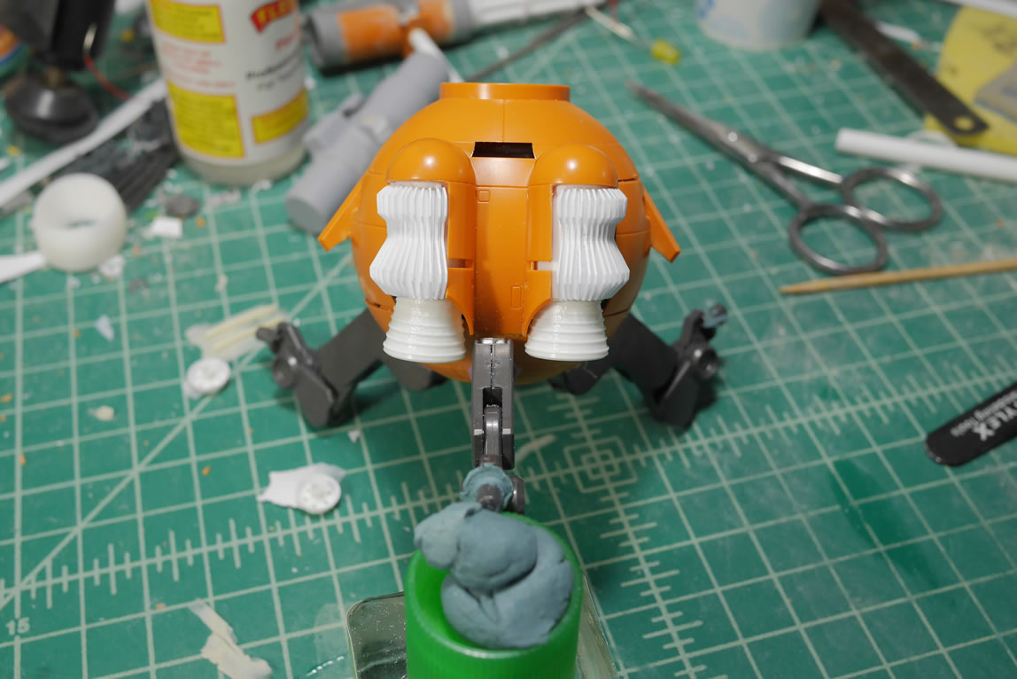
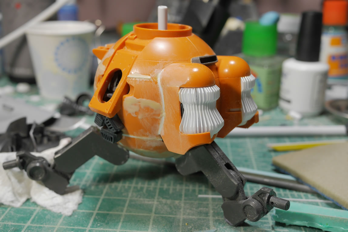
Here’s a comparison shot of the original fin to the new smaller and sleeker version. For the base of the vent assembly, I went with a larger diameter styrene tube. These two changes in the sizes of the fin and base make a HUGE difference in final design. I think I like the new design better. This is a fairly simple change and I believe this helps it become more realistic than the 2nd attempt. I have comparison with the thruster attached as well as a comparison shot of the two on the main body part. As I build, I will scrap things I spent a decent amount of time building because it just didn’t look quite right. I’m learning as I work too, so the time spend in development is not a complete waste. At the end, I think this evolved in the right direction.
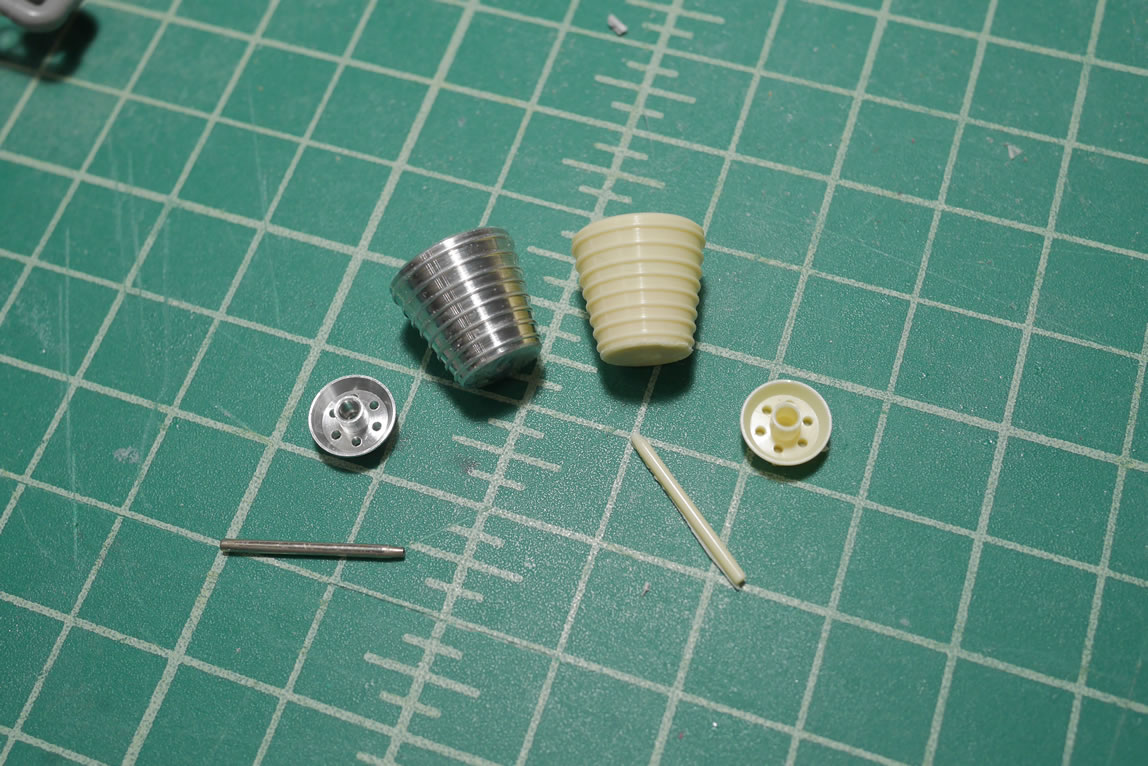
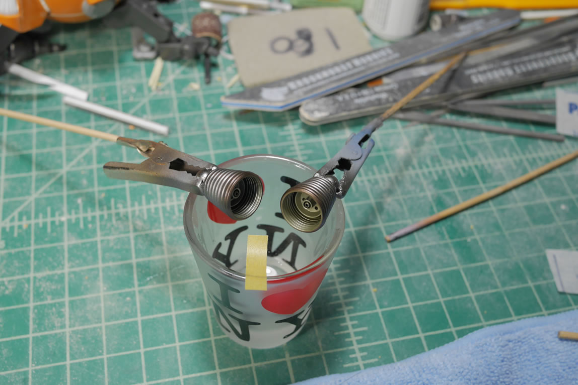
Speaking of metal thrusters, I made a mold of the original metal thrusters and casted them in resin so I can have a lighter overall model (the metal adds a decent amount of weight) and I can just make more in the future if I want to reuse this design. I also prefer painting resin copies over painting metal any day.
I did a quick live broadcast for the resin casting portion of this project:
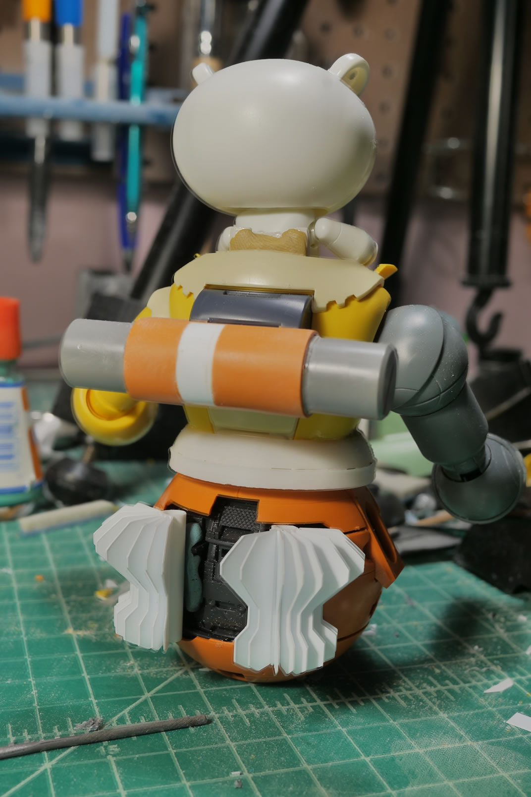
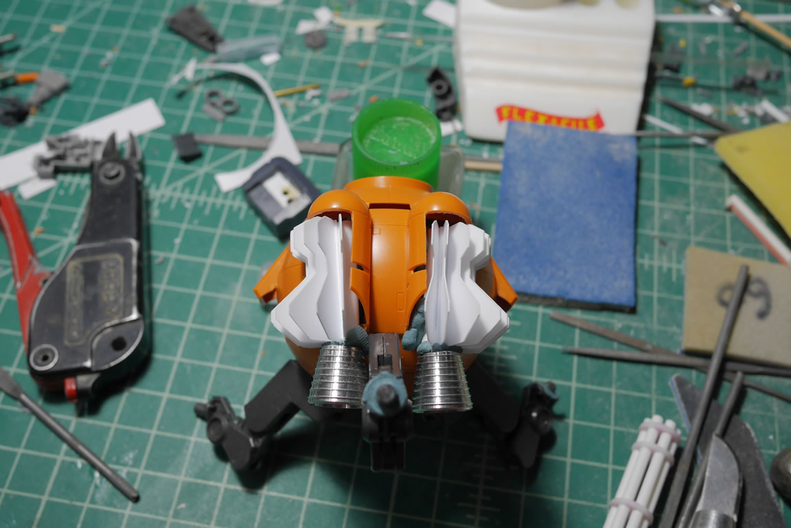
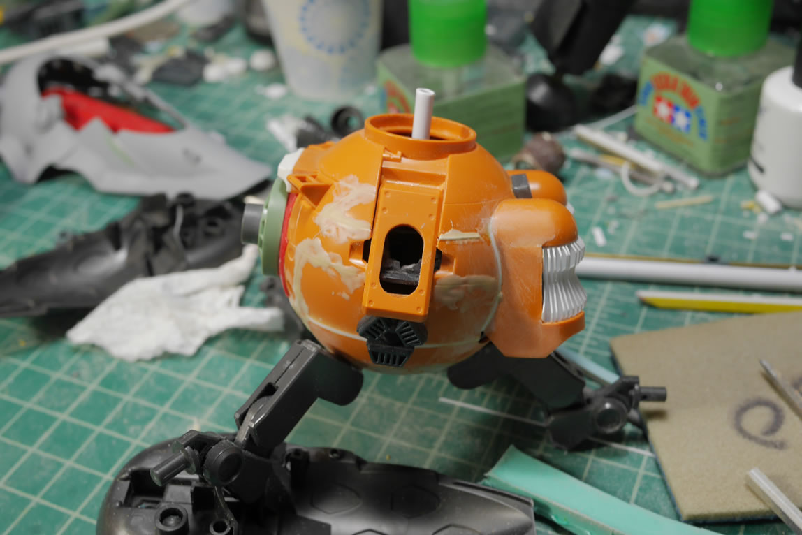
Returning to the newly redesigned vents, I need to start building up some structure to compliment the tubes with fins glued to it. This will help transition the part to the main body piece. I started cutting up the original Ball thruster internals and glued them to one side of each vent piece. This also helps with the fit of the whole assembly so that it sorta looks like it belongs there and not just glued haphazardly.
The next piece of structure is to fill in some empty space under and below the vent assembly as it sits in the main body. I have some left over internal pieces from the Ball’s side extensions that I cut off weeks ago. I trimmed those pieces to size and glued them into the bottom area so that there is an illusion of internal structures. The rest of the Ball starts getting some filler styrene and filler ABS putty.
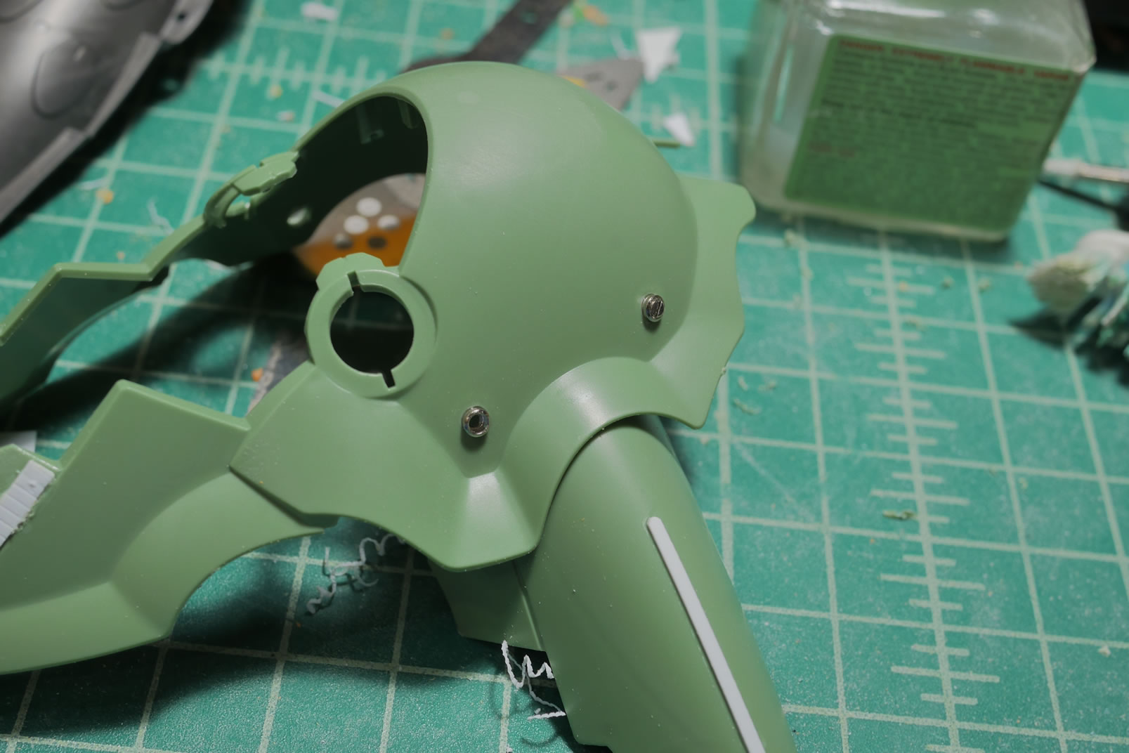
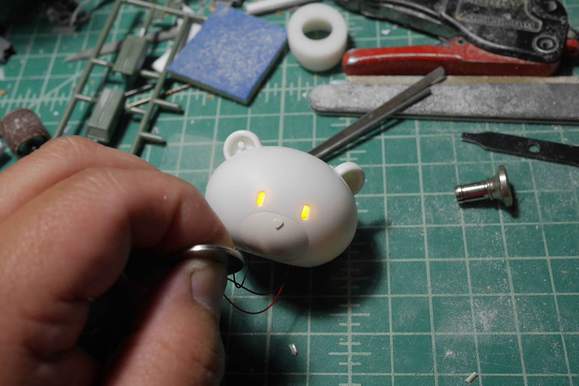
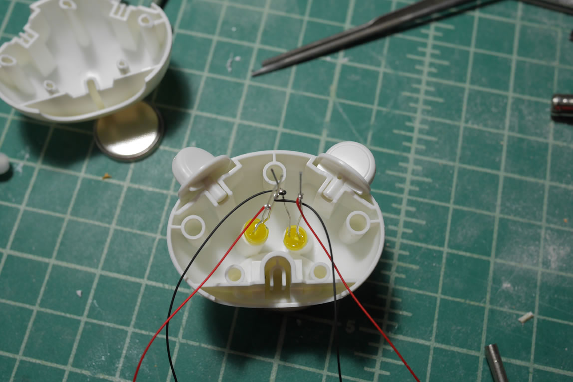
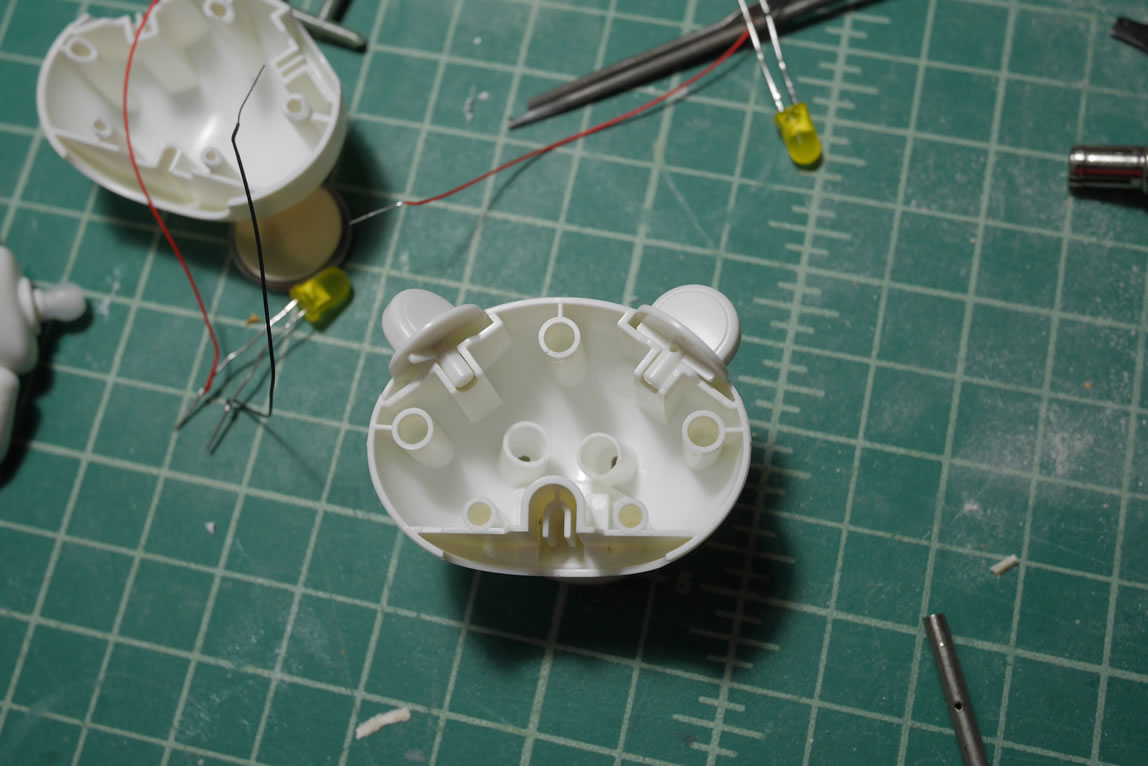
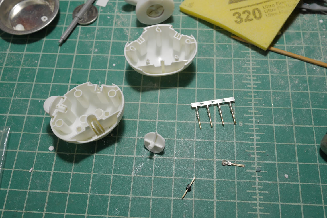
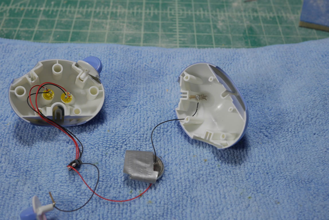
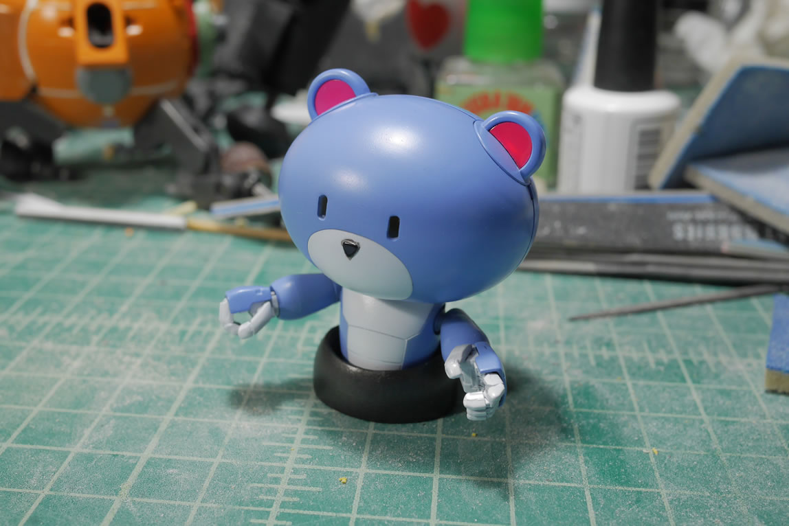
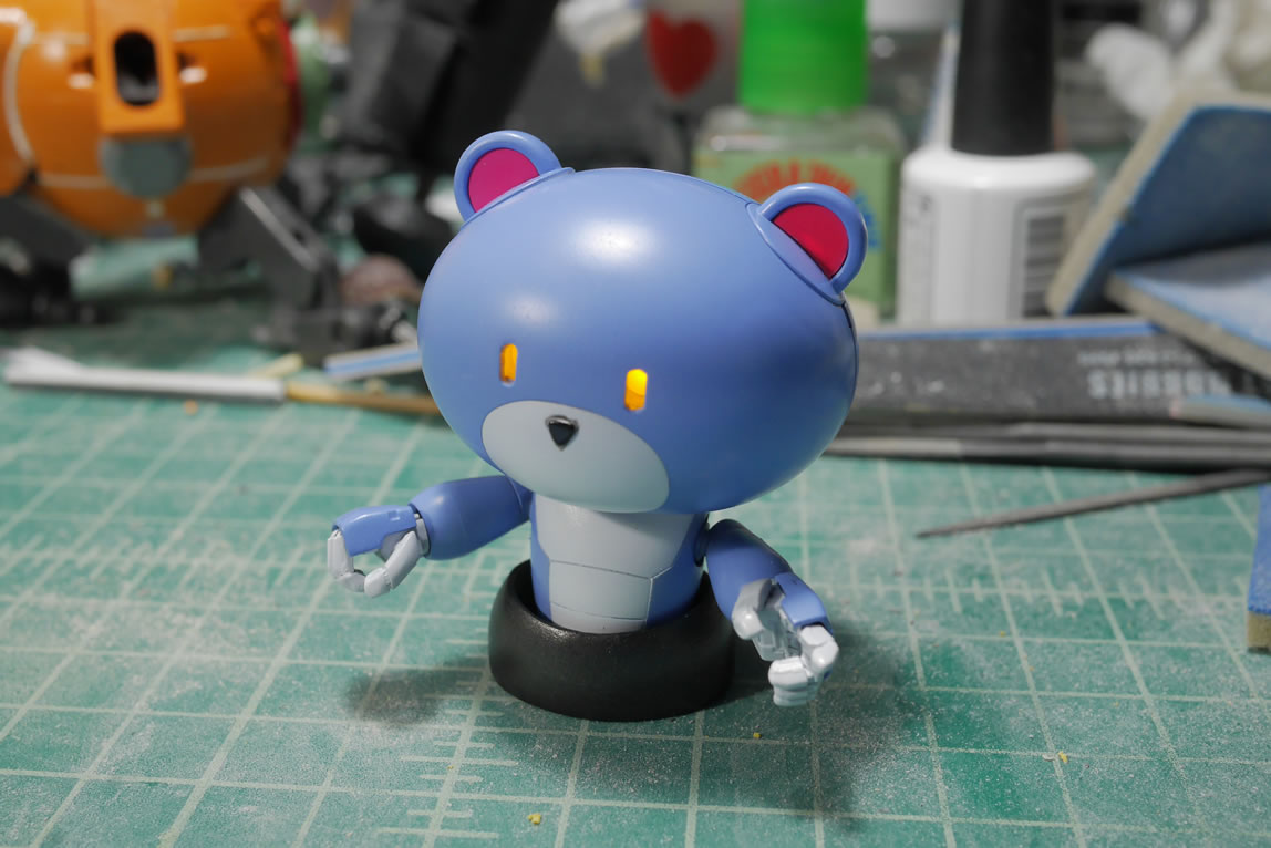
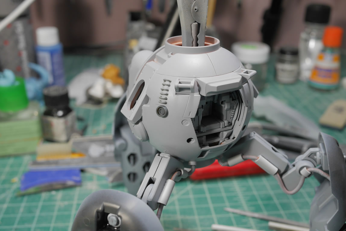
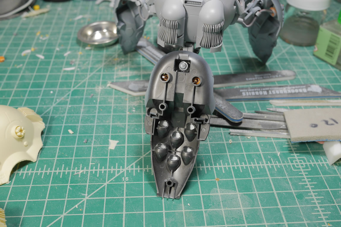
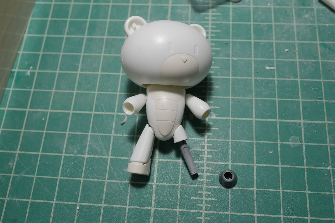
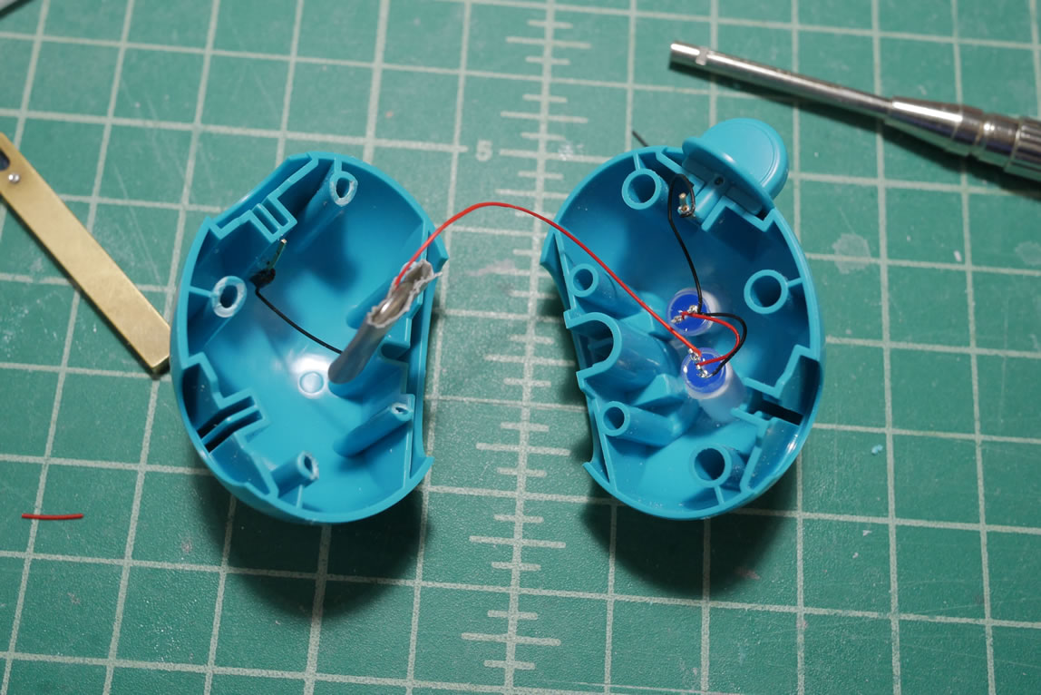
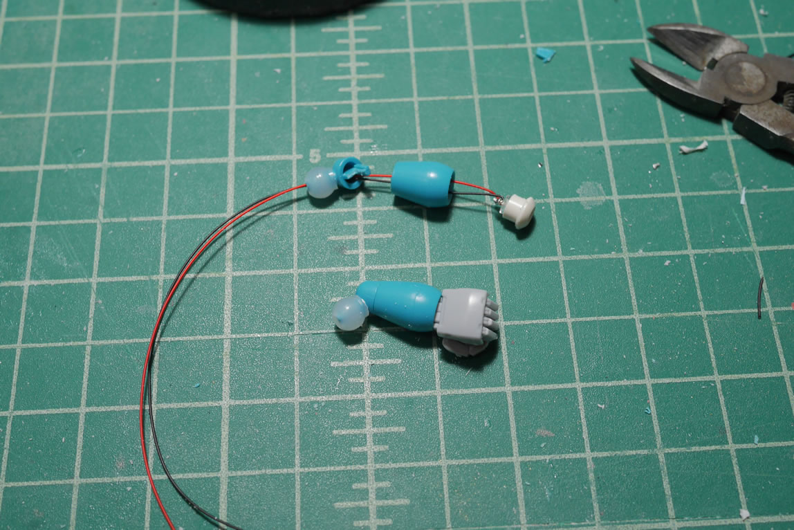
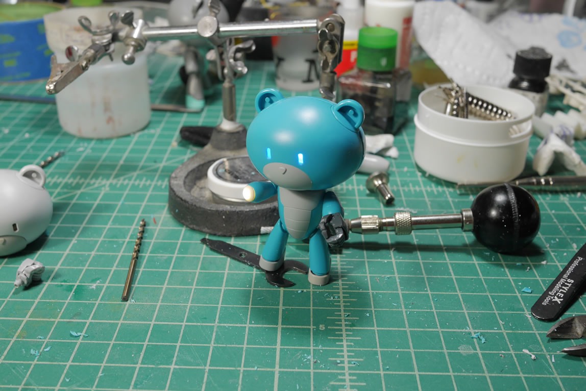
Returning to the pilot’s head, I wanted to add in some LEDs into the head. The first step was cutting out the eyes, which was done with a small drill bit to cut two pilot holes that were then used to widen and clear out the excess using the existing eyes as a guide. Next, I glued some styrene tubes inside the head behind the eyes as LED holders. The LEDs are wired in parallel (positive ends together and negative ends together) so I have one positive and one negative coming out from the LED assembly. I then gather some metal leads so I can build a switch assembly. The ears of the Petit-bear swivel, and it just made sense that this would make for a perfect mechanical switch. I don’t have to do anything fancy with a reed switch and magnets. I don’t even need to add in a build in switch and have to hide it somewhere. The Petit-Bear’s ears are the perfect solution.
Here is a live broadcast for when I built the switch assembly and you can watch the process here:
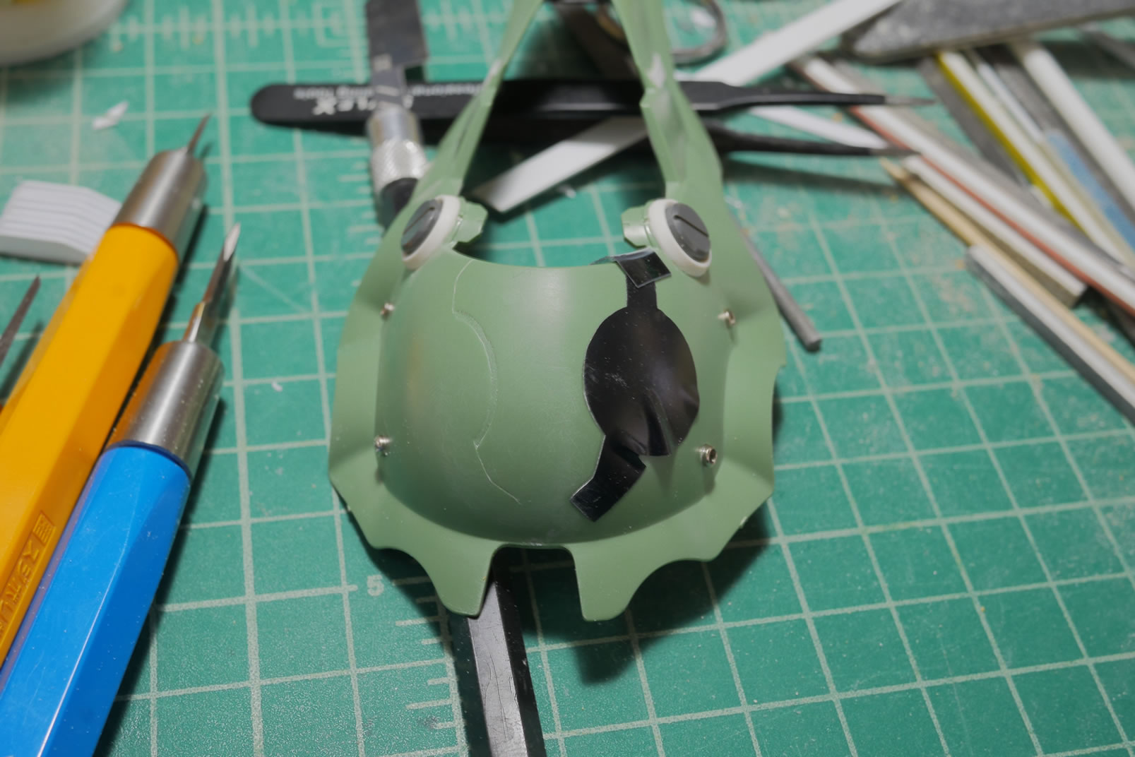
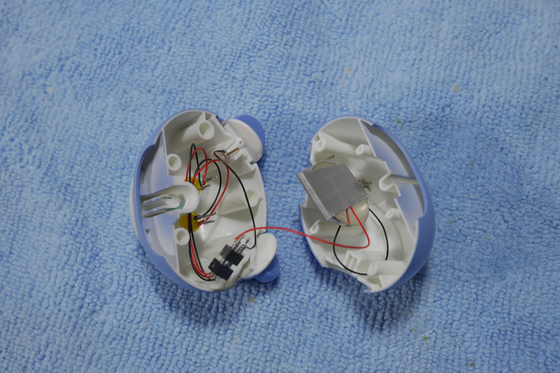
After all is said and done, here are some pictures of that final assembly. The LEDs are one assembly wired to an ic pin plug. This is connected to another ic pin plug that has the negative wire broken up between the switching mechanism on the ear and the back of the head. The positive end from this ic pin assembly is just taped to the positive end of the battery. One negative lead is taped to the negative side of the battery which is connected to the other lead that is glued to the inside of the head.
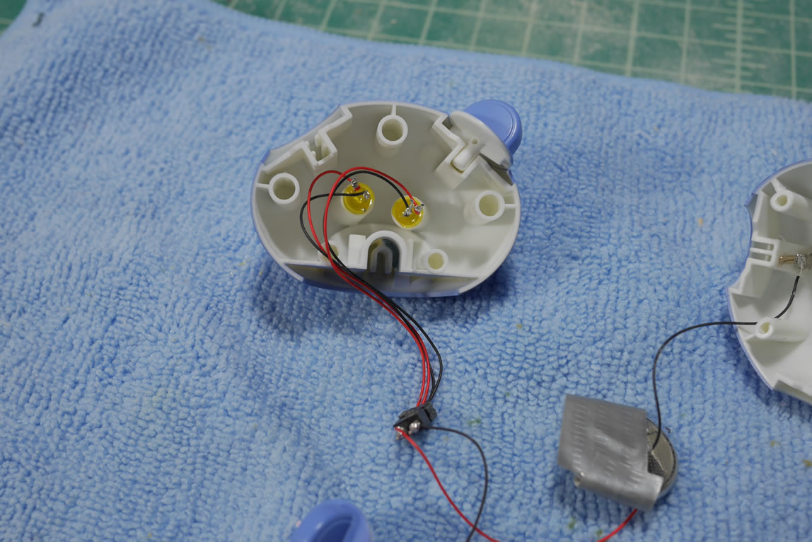
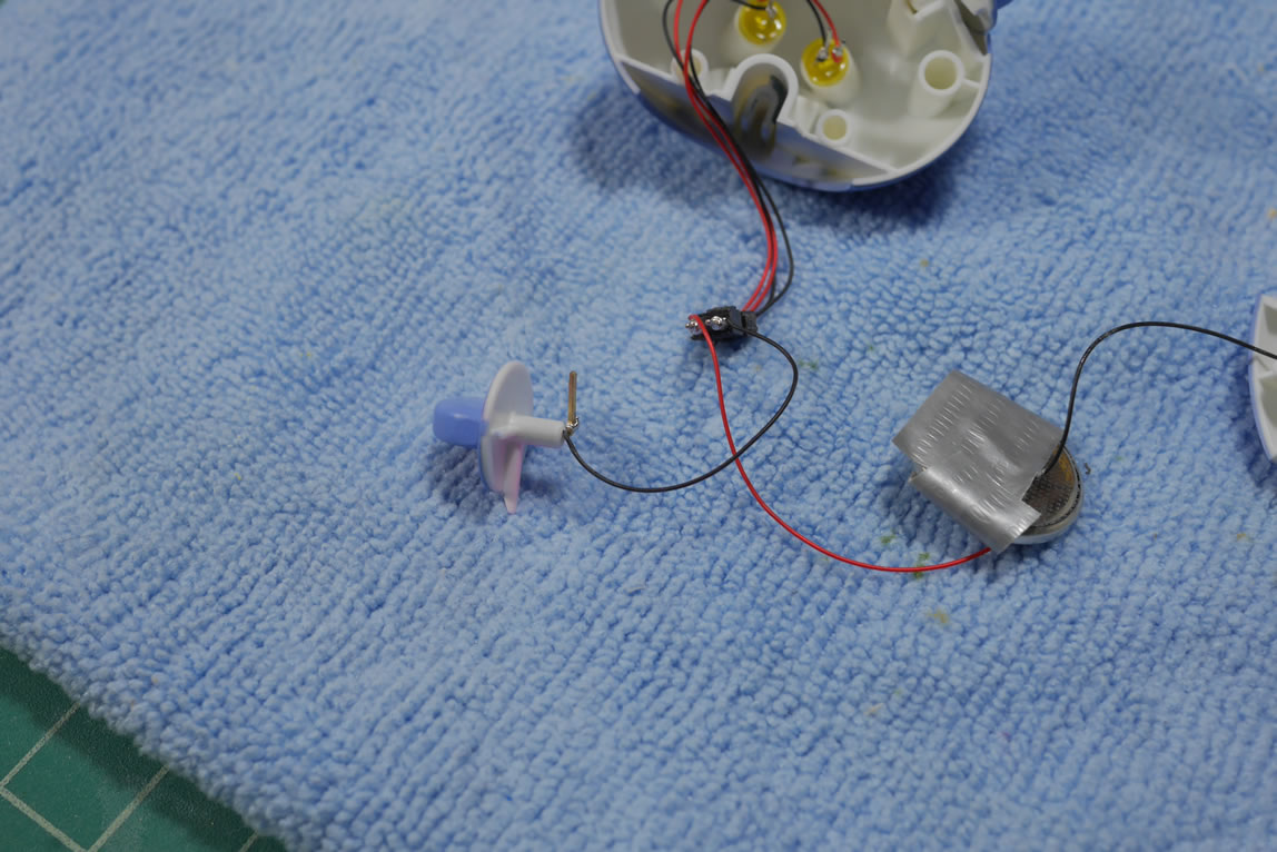
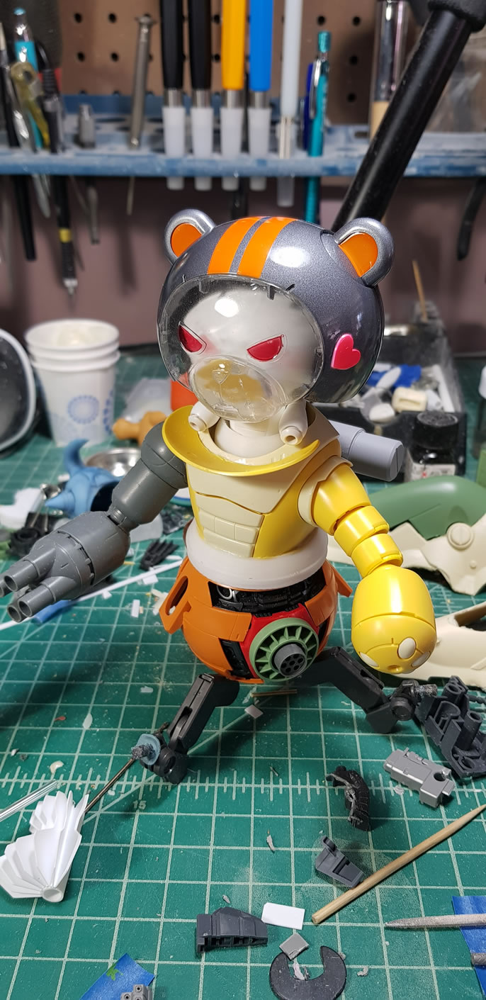
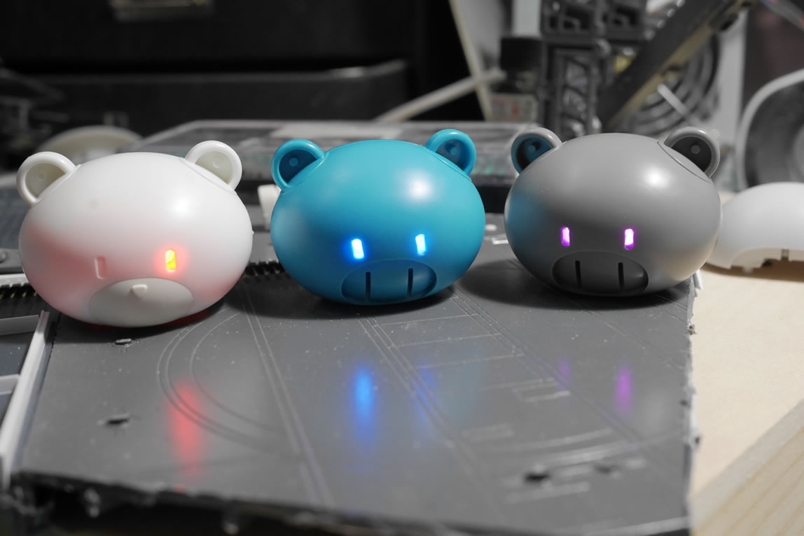
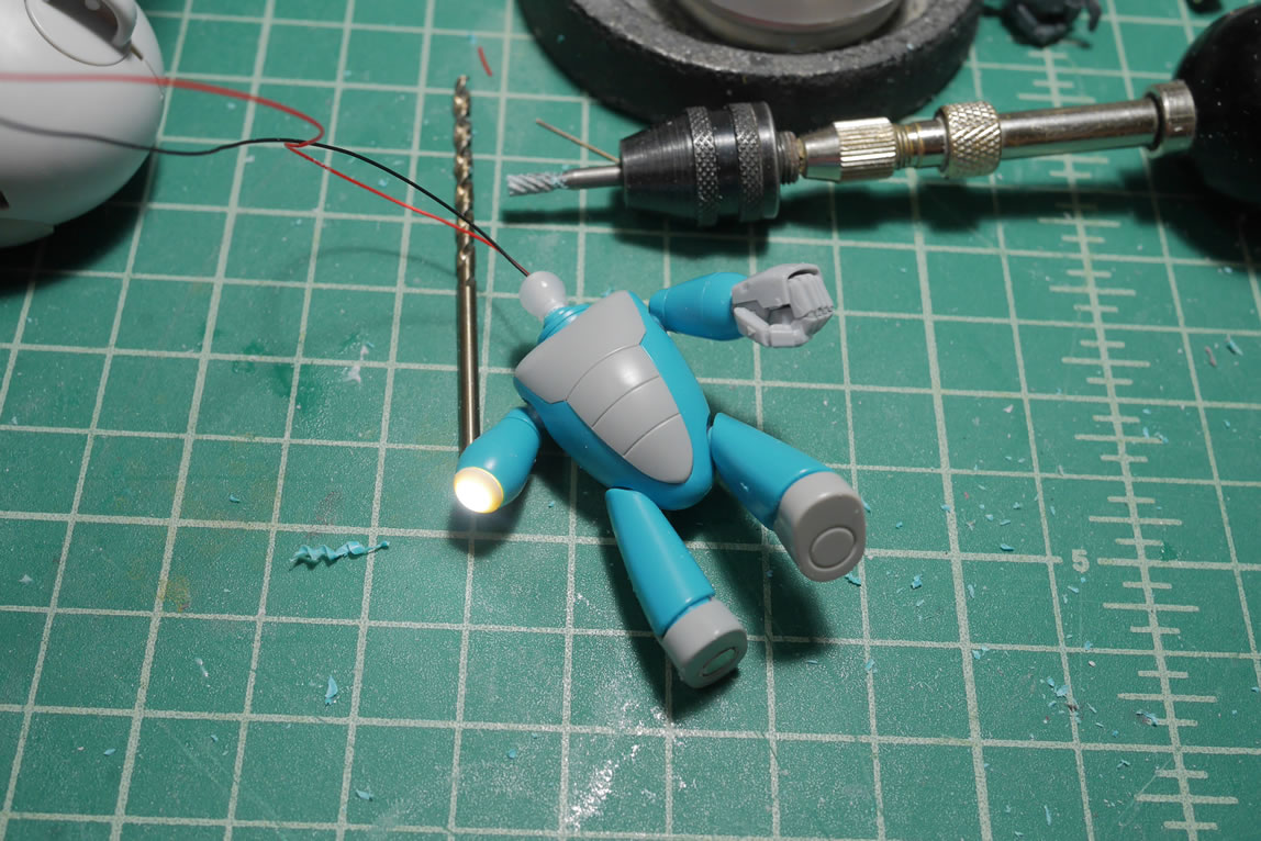
Once assembled, a slight twist of the ear connects the two negative ends which closes the circuit and turns the LEDs on. Twisting the ear back breaks this connection and the LEDs turn off.
Here is a quick little video demonstrating this since the earlier video from the live broadcast is over saturated and too bright so it was difficult to see the operation.
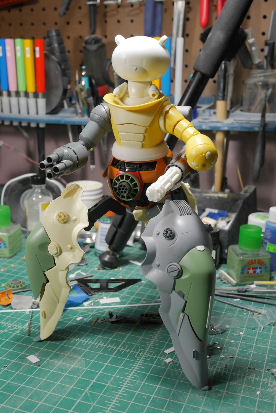
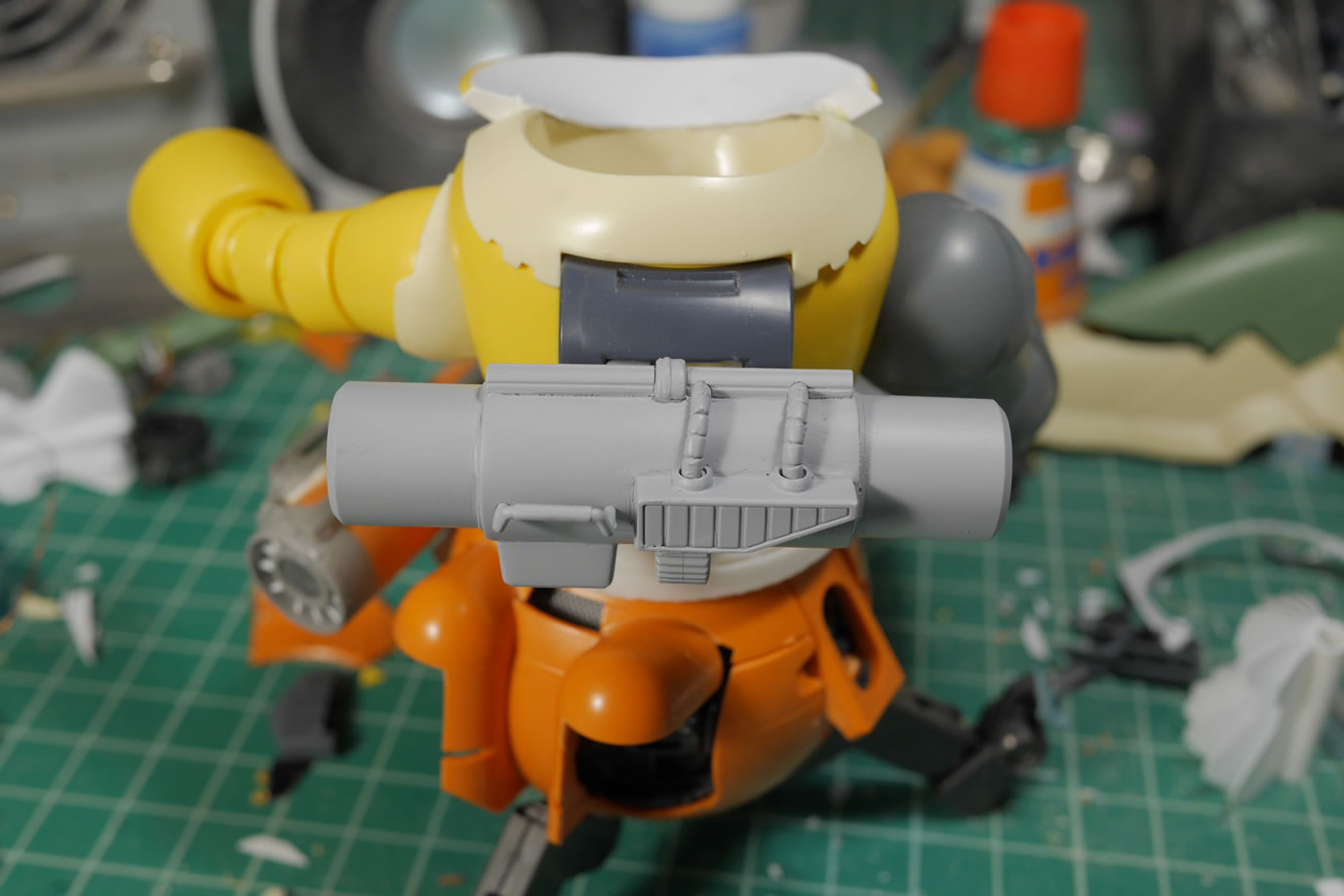
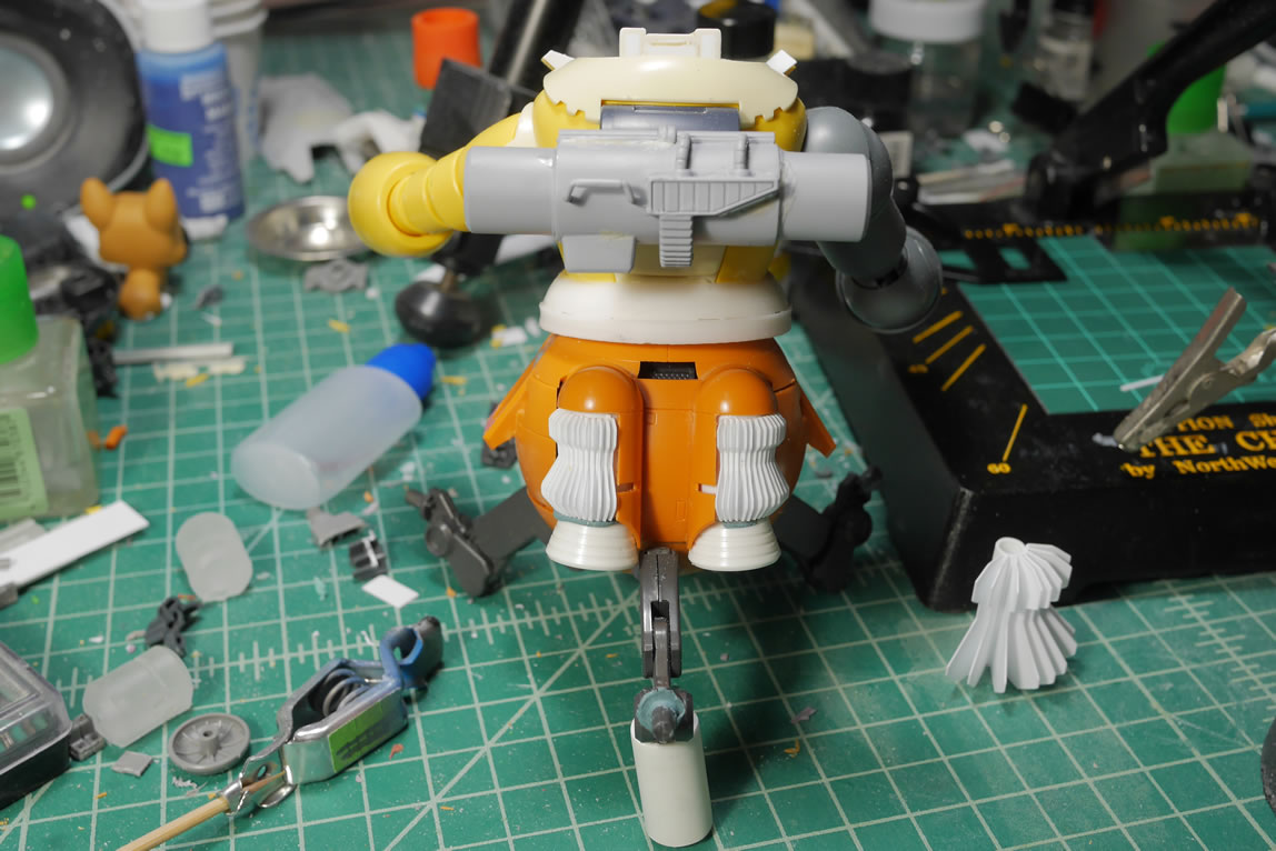
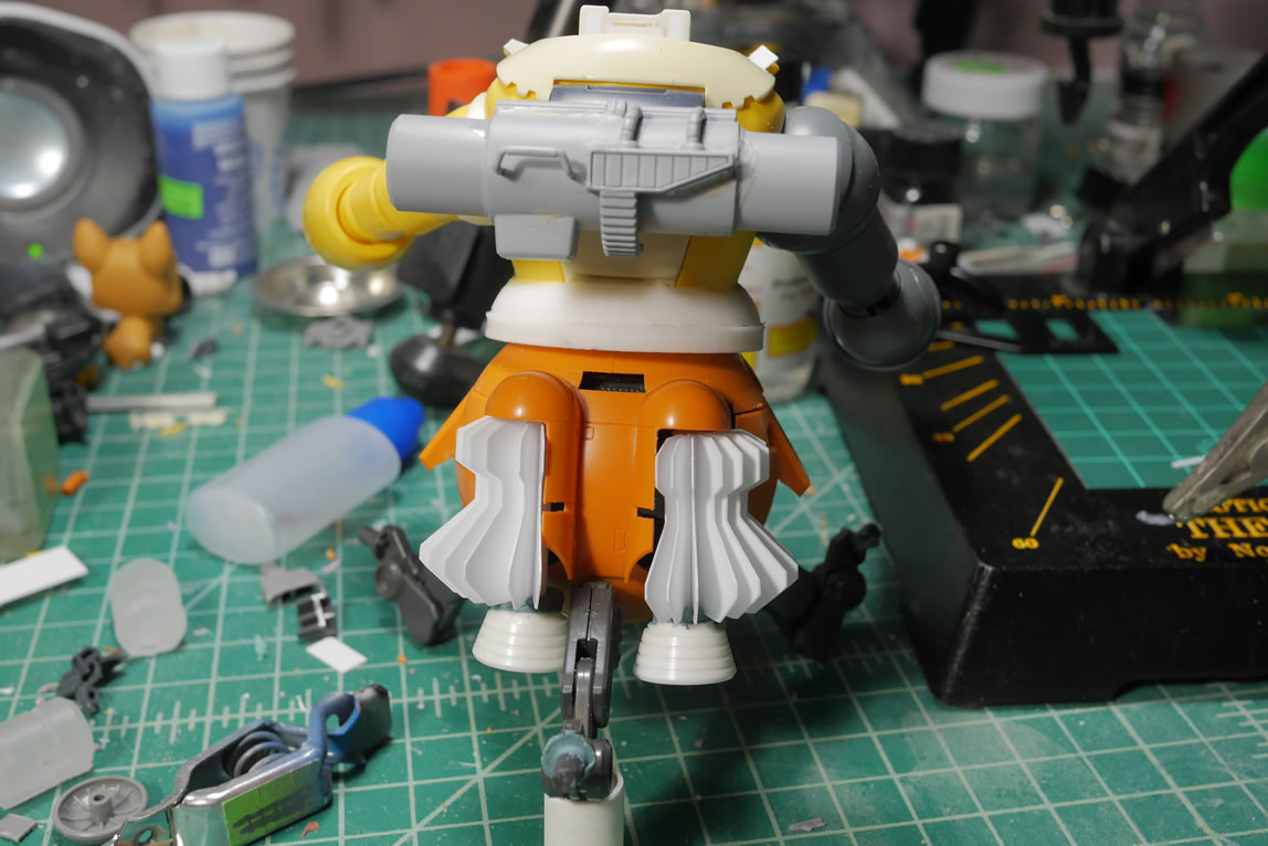
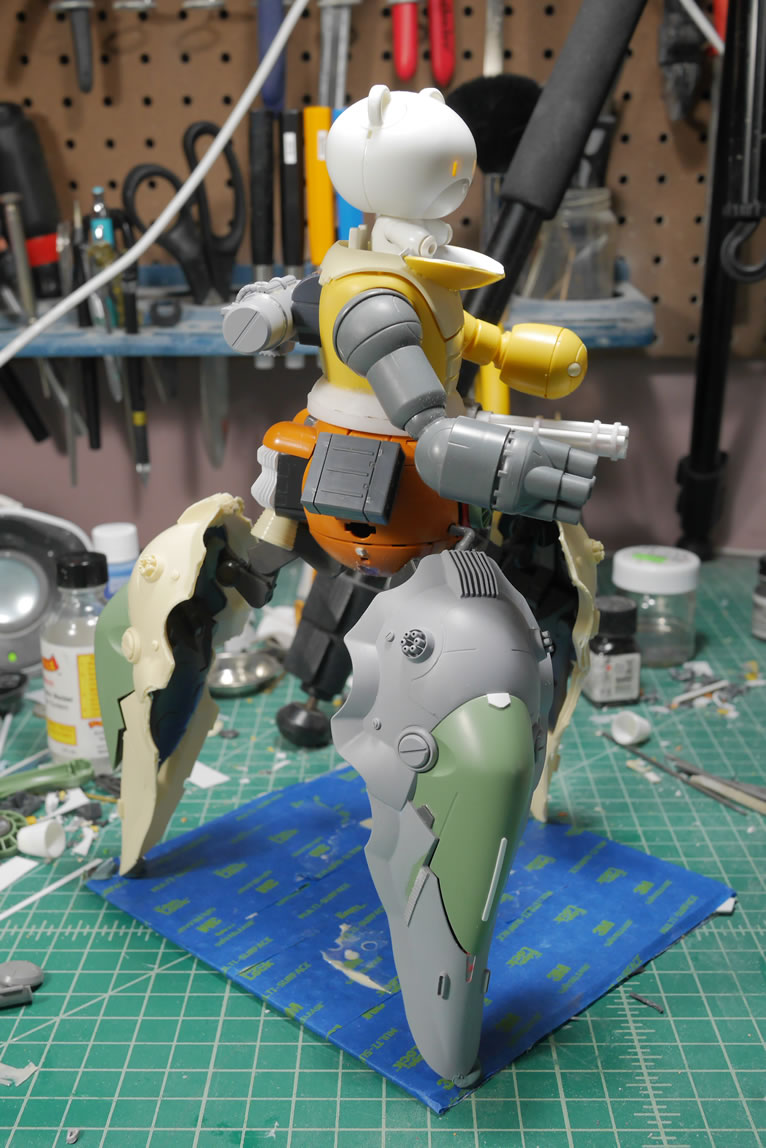
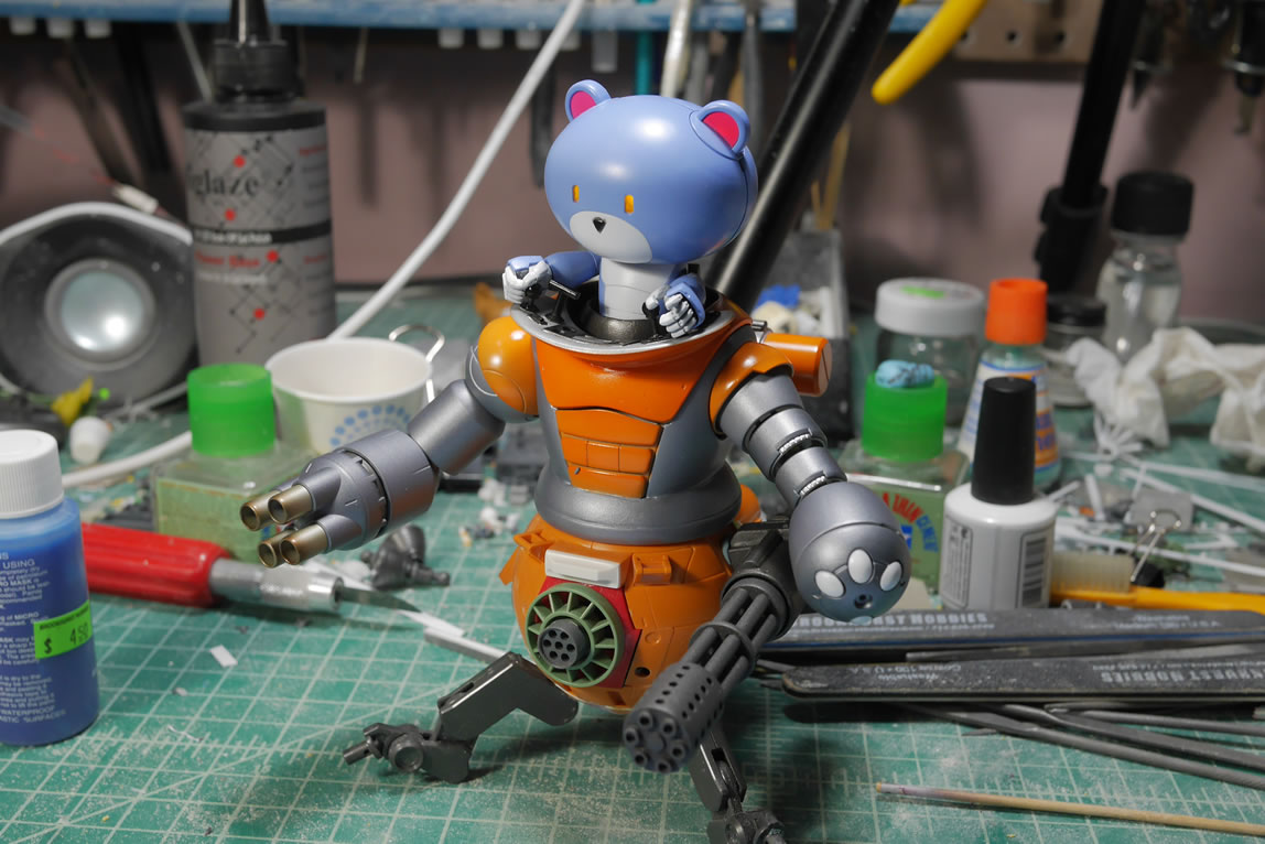
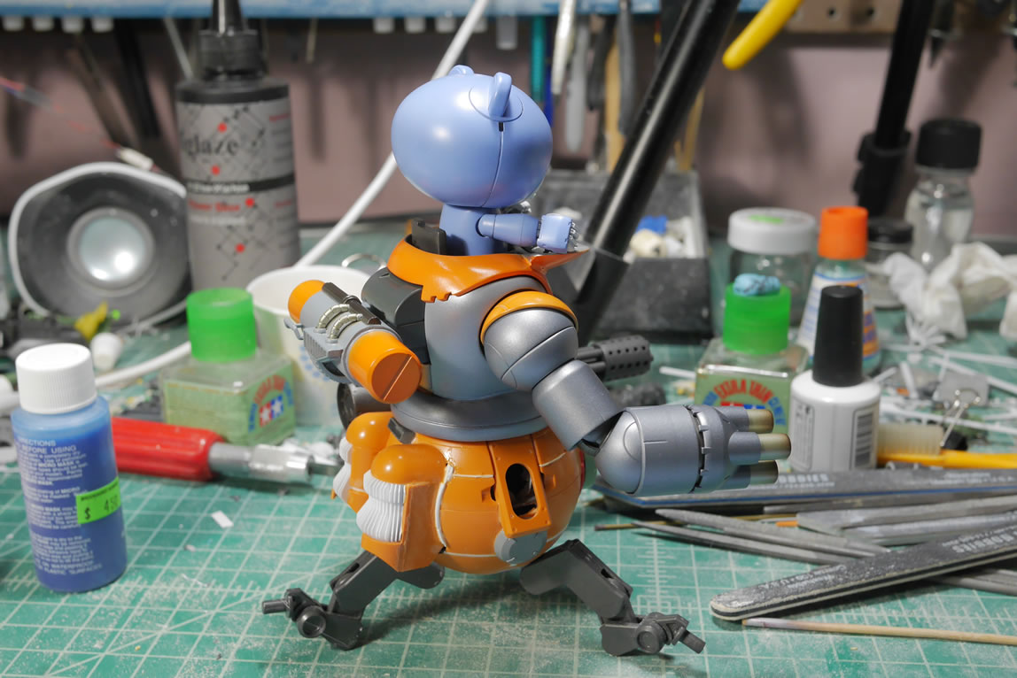
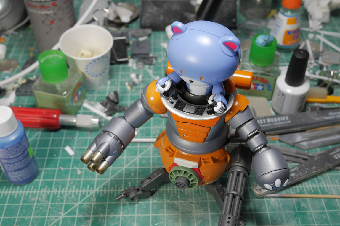
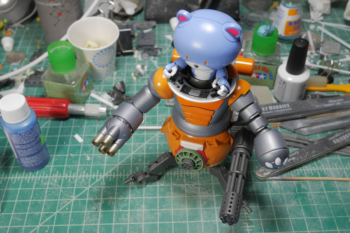
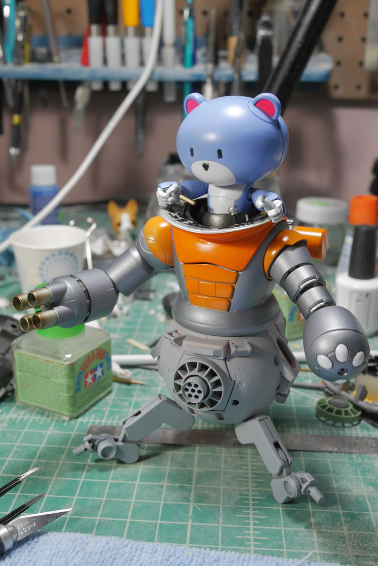
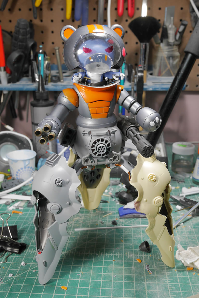
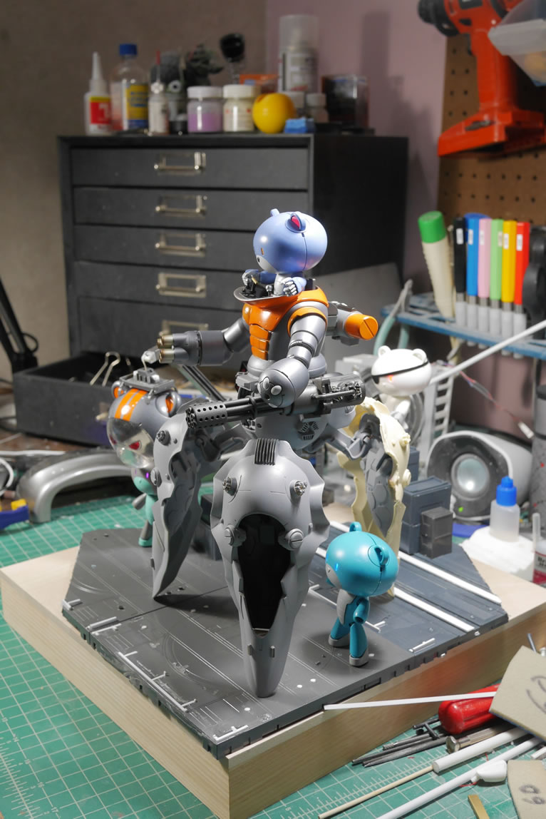
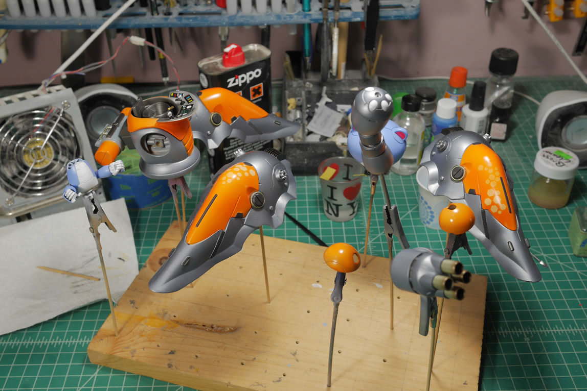
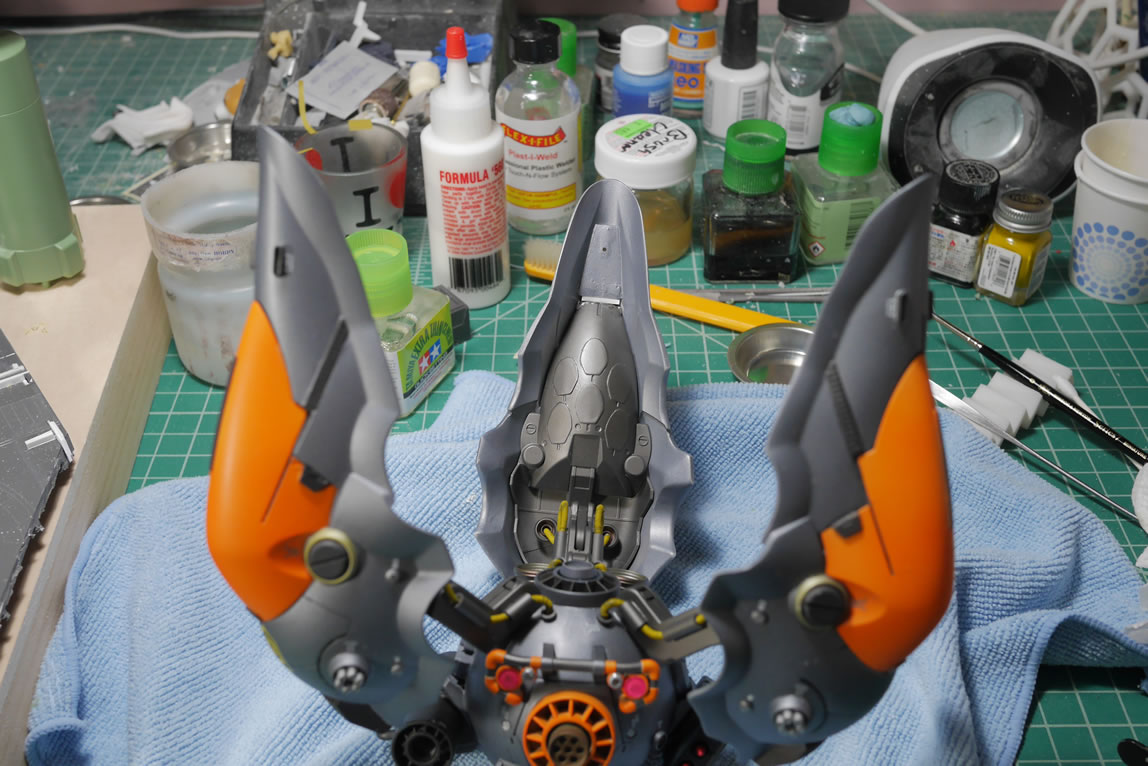
Since I had most of the principal pieces built; I did a quick mockup to again, get a good visual on the project before continuing. The gatling gun is coming along, the backpack is actually primed and getting lots of clean up attention, the new vents and rear thrusters look good in the overall assembly, and things are starting to come together.
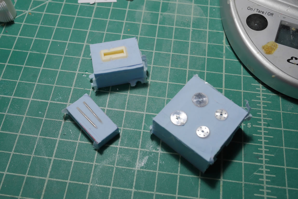
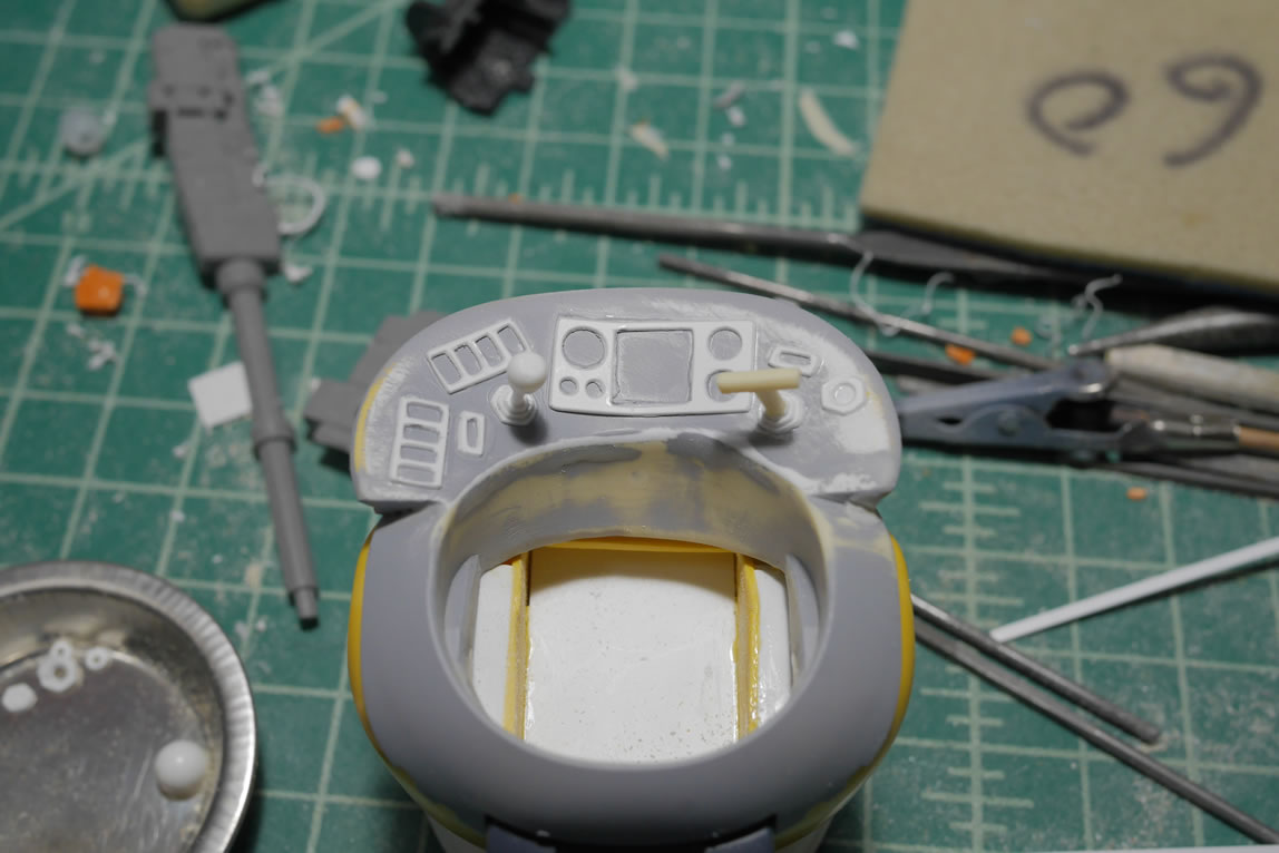
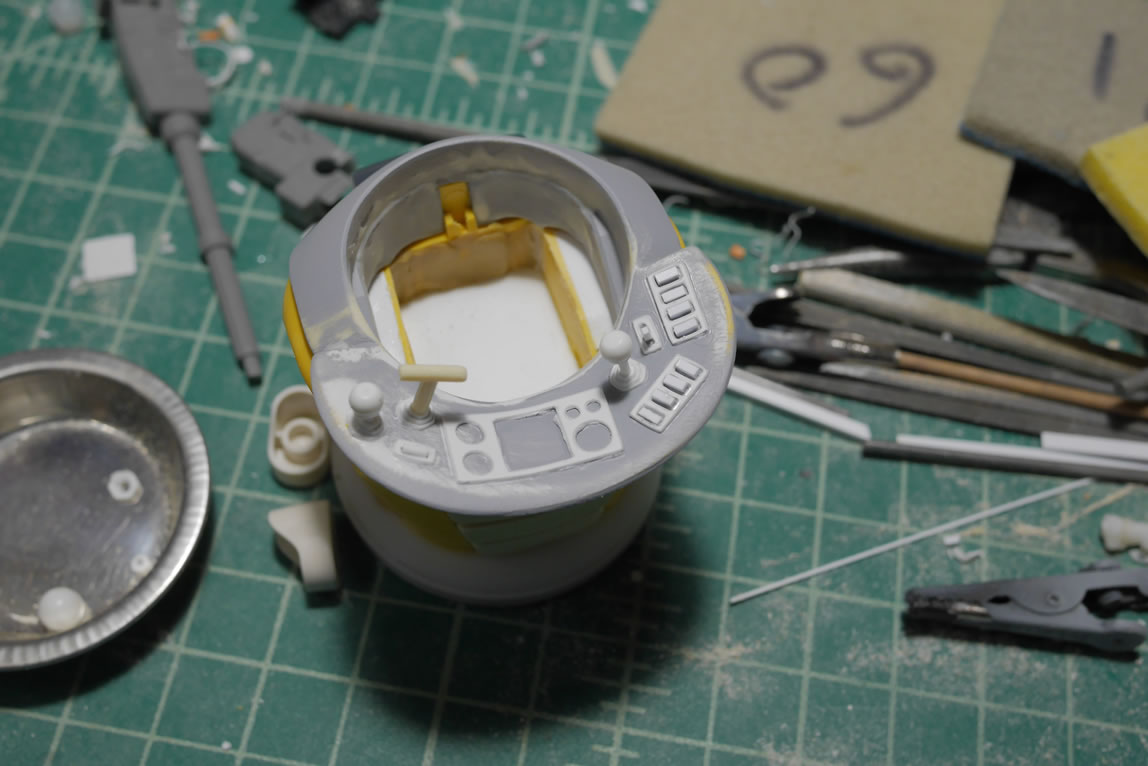
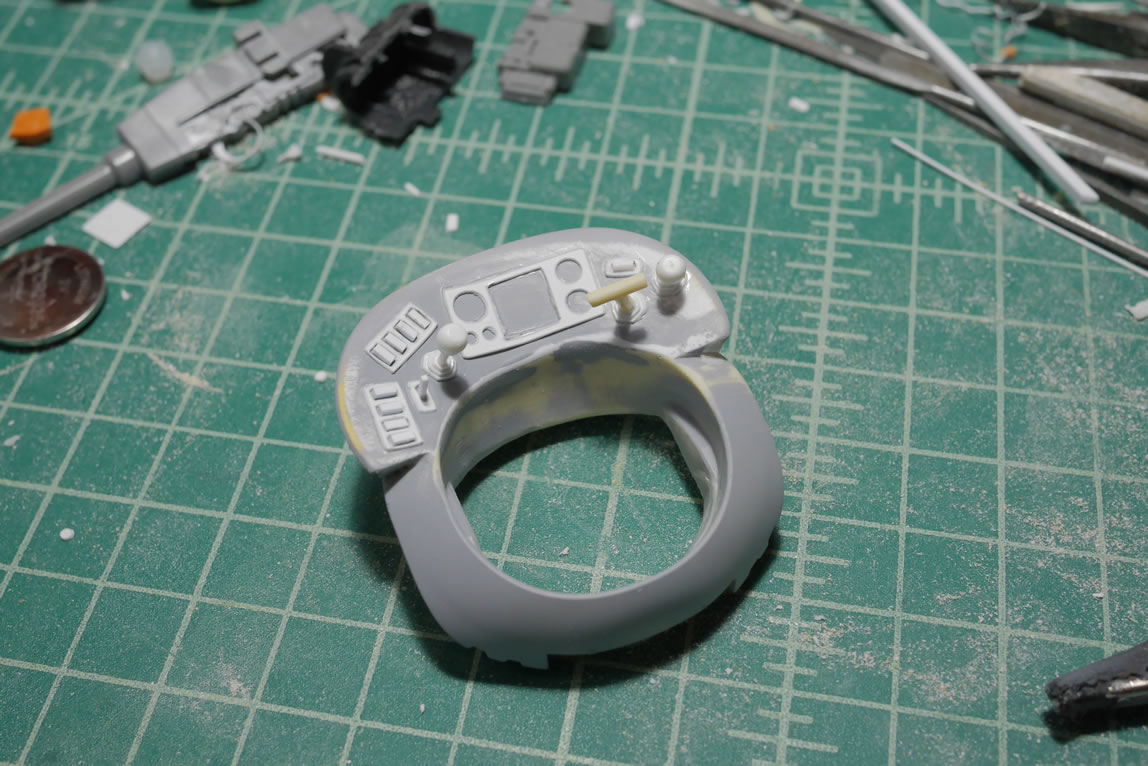
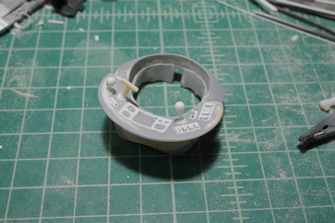
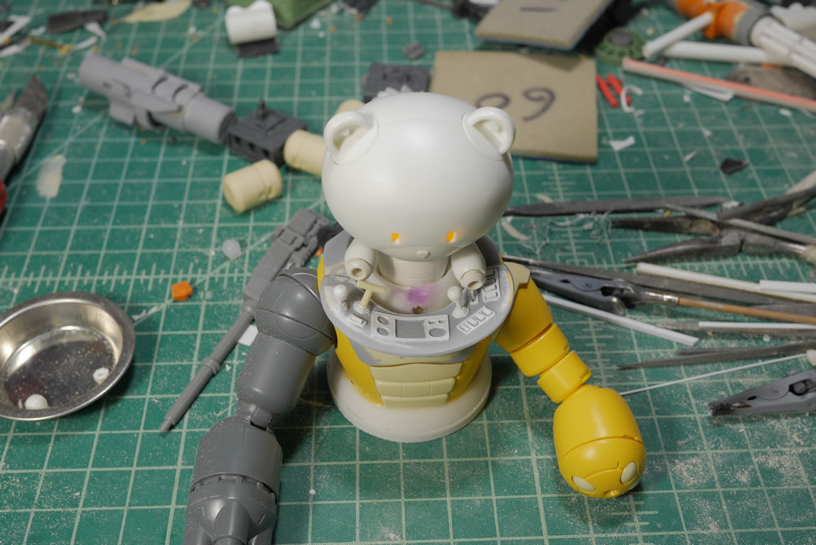
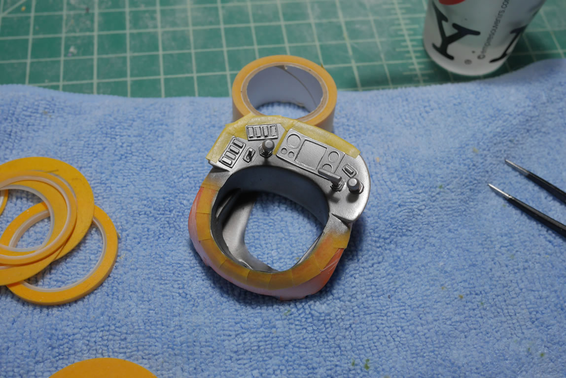
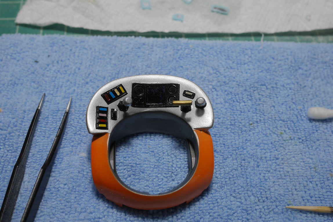
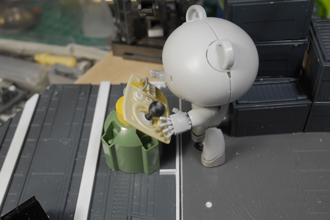
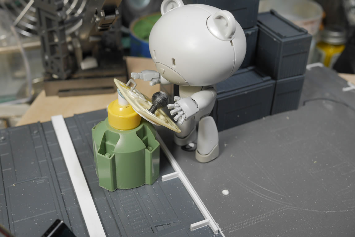
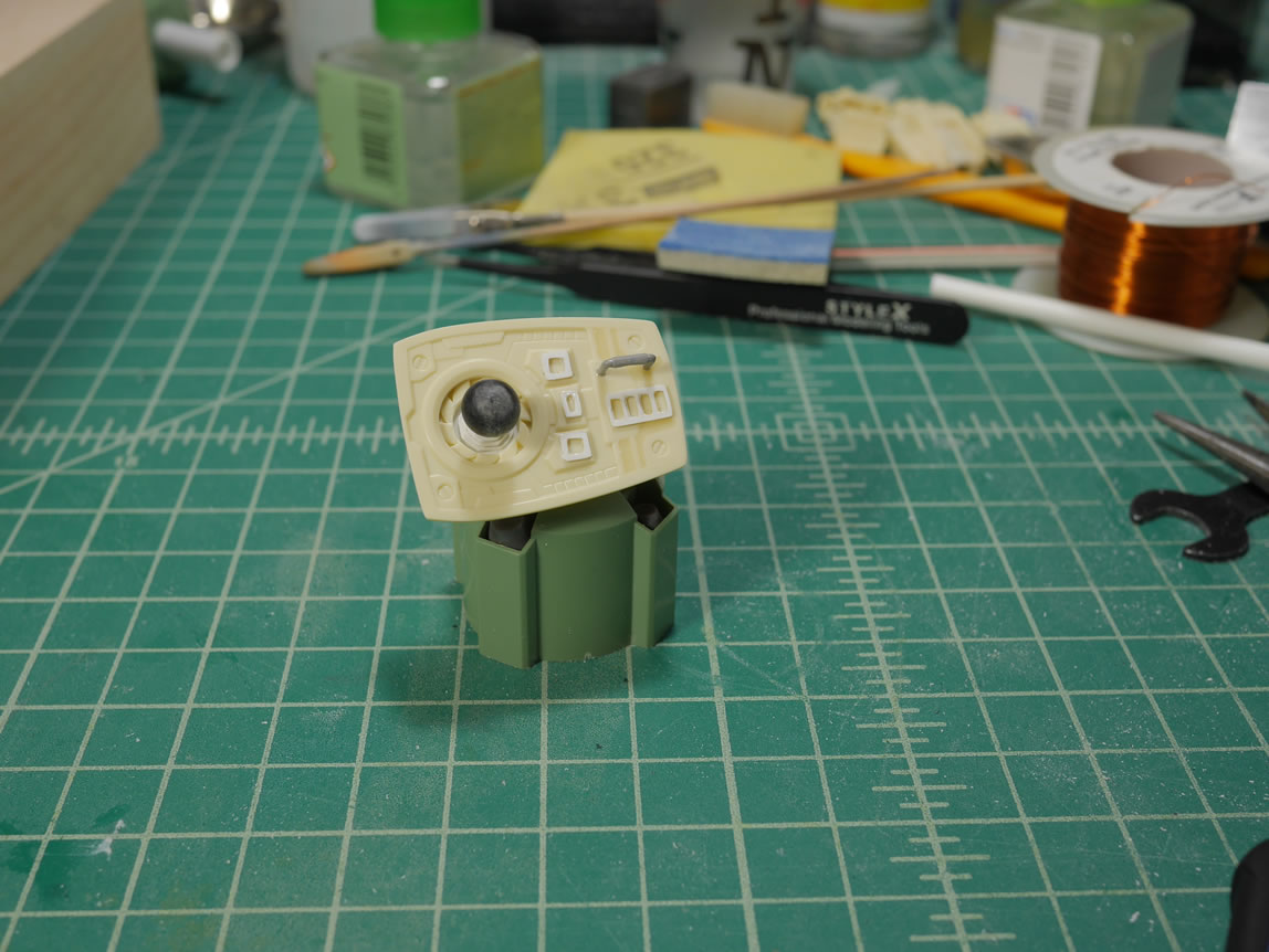
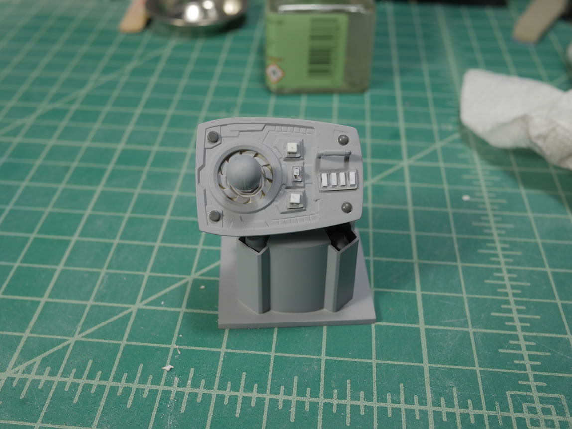
To stay true to the Panda-Z style I’m emulating; I need an instrument panel. I did some quick designs with the cricut machine and cut out .2 mm styrene. One of the drawbacks to the cricut is that the smaller the scale, the less precise the cuts. But this still beats the hell out of just gluing strips of styrene and I since don’t have OCD; this won’t bother me. In the overall big picture; will look fine. I did a quick overlay over the instrument panel to get a look. Then added the bearguy in the seat to see how that all looked with hand positions and everything. Then it was off to priming the upper torso piece to finish the clean up before getting the instrument details glued to the panel.
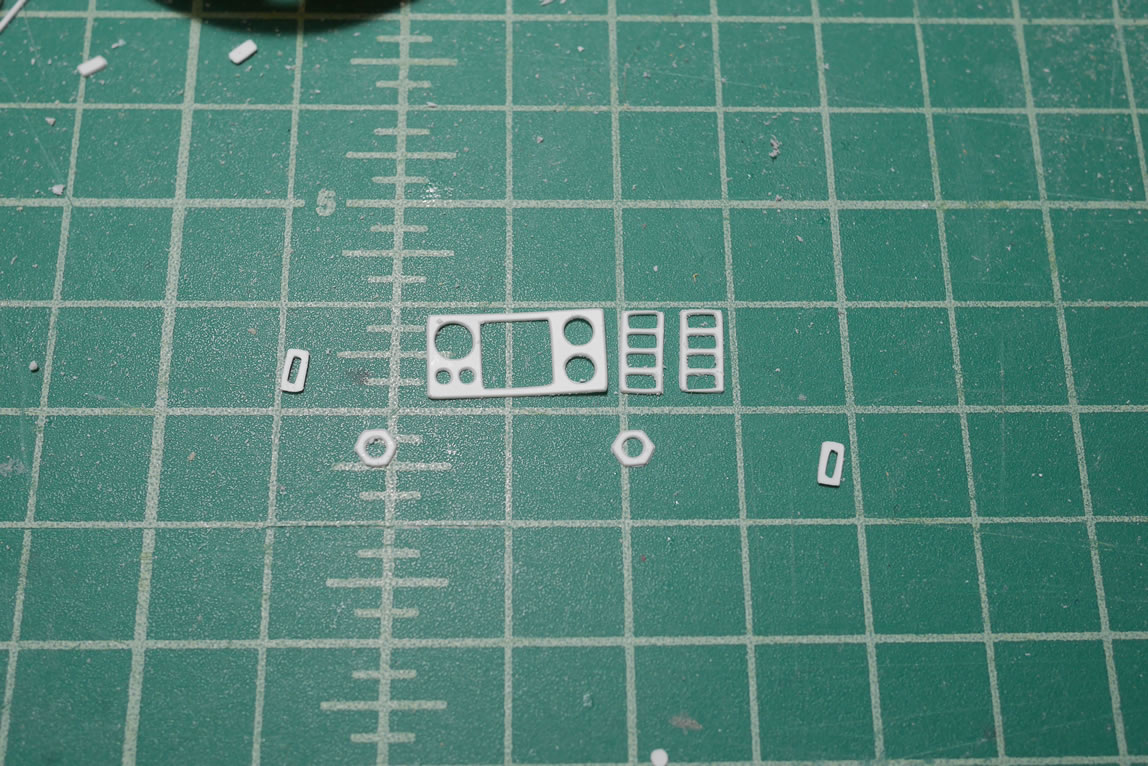

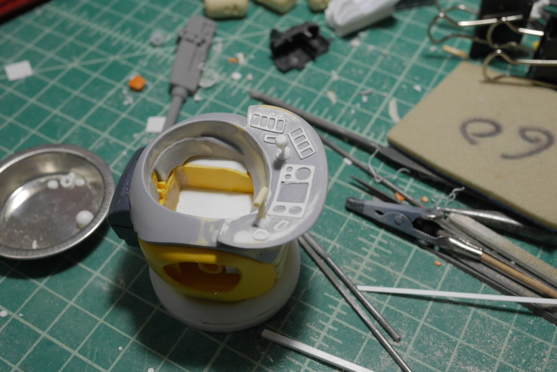
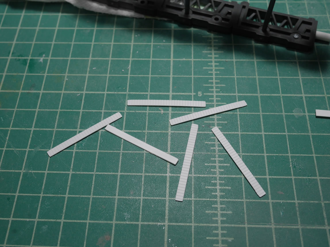
Some styrene strips are cut and glued into position as buttons. I glued in a thinner piece of styrene to simulate a pushed button. I made some hex cuts in different sizes so I can stack them to create a shifter boot for some of the controls. This should be good enough for some quick instrument panel details.
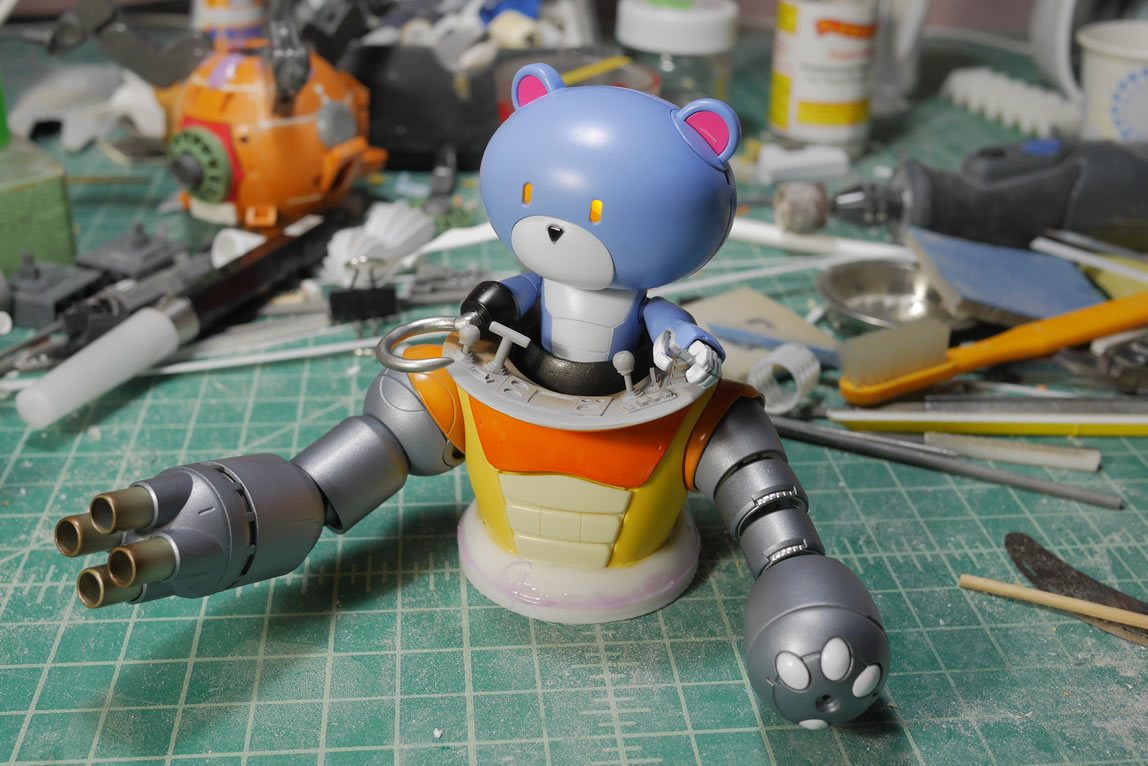
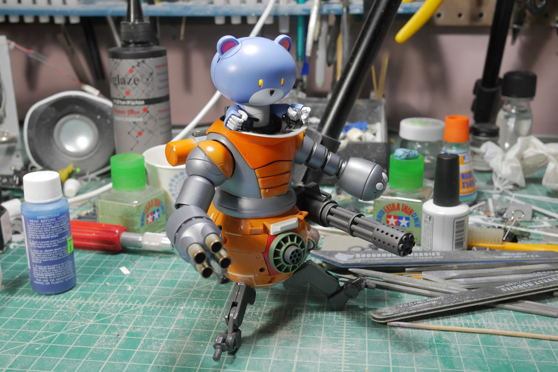
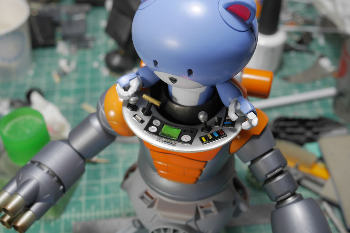
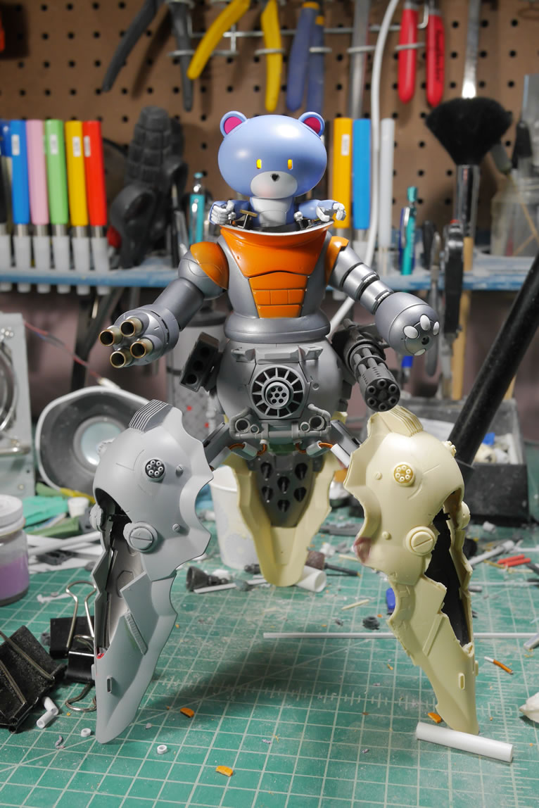
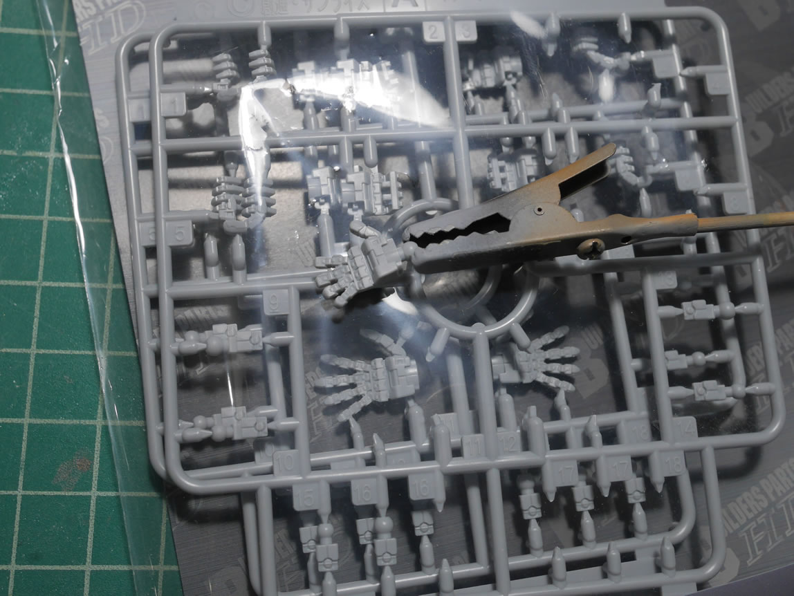
In test fitting the bearpilot, I noticed that the stock petit-bear doesn’t actually have hands. So it just looks odd to have a control panel with knobs, buttons, and joysticks and no hands; but I can see the comedy in that too. However, I still want to add in some hands, so in come some builder parts 1/144 scaled hands. The hands as they are look a little creepy, but I think I can find a solution to make it look better.
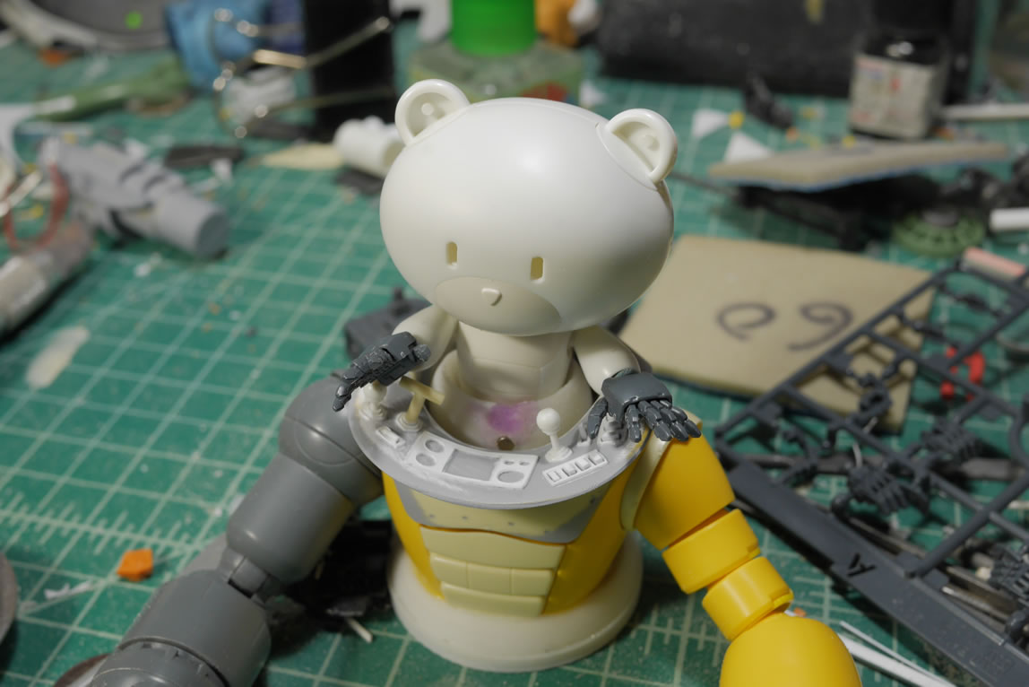
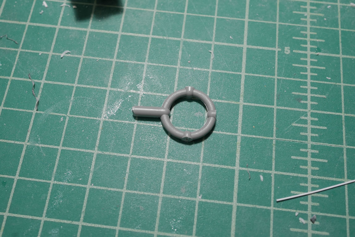
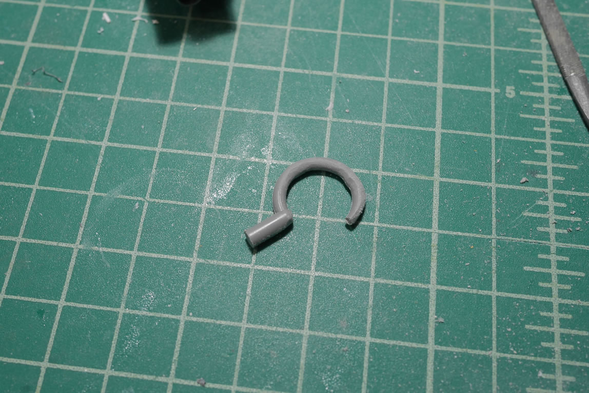
Making posts to reddit/r/gunpla; I get all sorts of constructive criticism and recommendations. One such recommendation was to replace a hand with a hook. This was fairly easy since the kit trees always has a circular center piece that I can just cut and sand down to create a hook. A number of the upper torso parts are primed and painted. It’s always good to see paint progress.
Once the paint has had enough time to properly cure, time again for quick assemblies and a mockup. I made some modifications to the 1/144 hands by cutting off the end joints shortening it from 3 to 2 finger links and some creative sanding with files to fix the hard to reach embedded digits. This helps scale things nicely and is also another recommendation from reddit. The arms have magnets so that I can easily exchange the hands for the hook or even the non-hand originals. I think it looks best with hands; but I now have options.
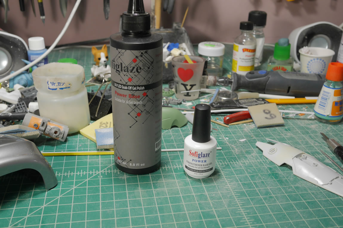
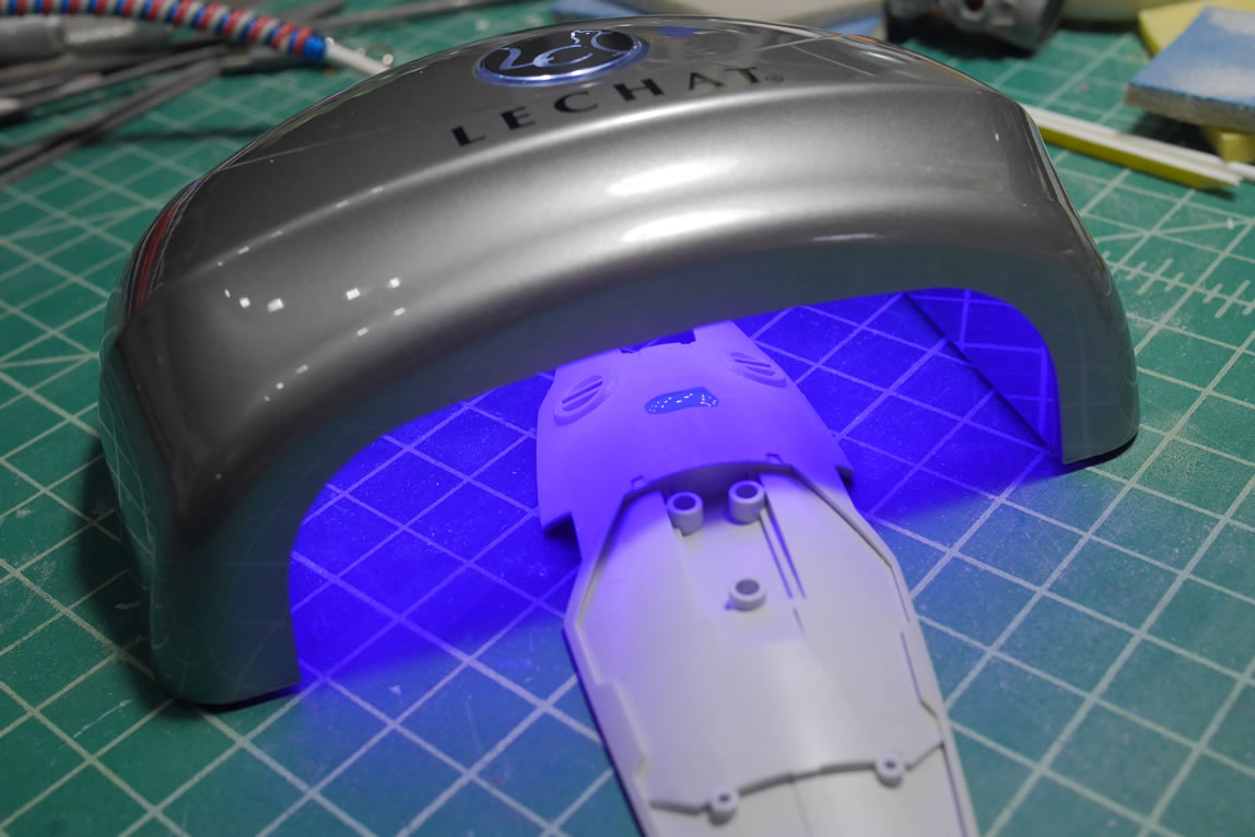
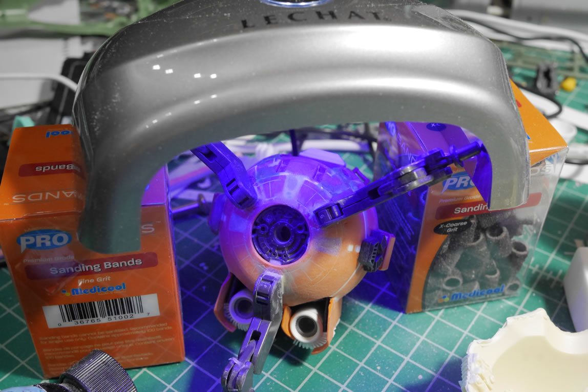
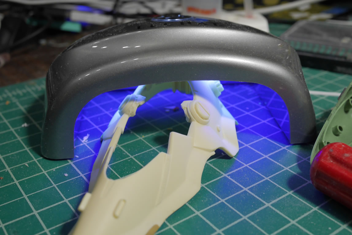
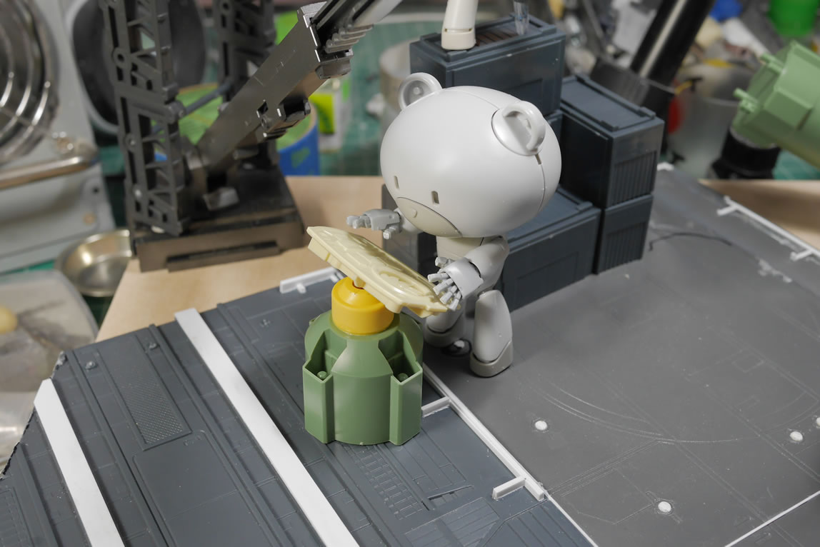
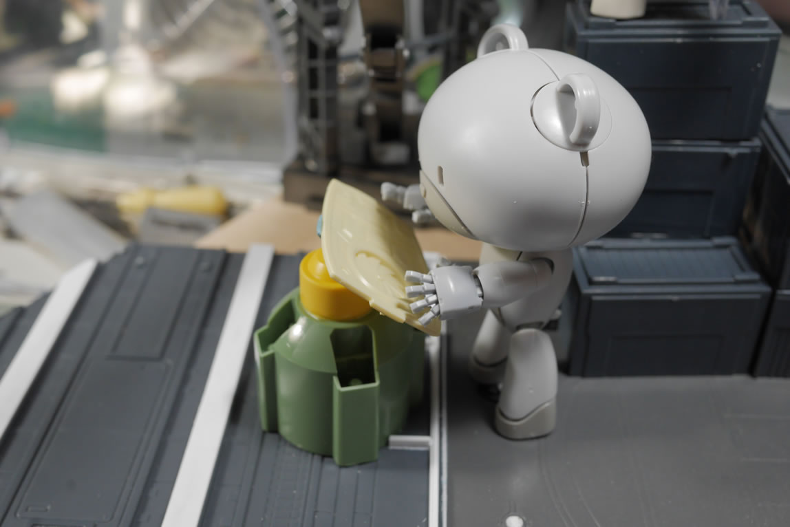
Next up is a product that I sorta discovered from my wife’s experience with nail care. This is a foundation gel that cures under UV lights. The stuff goes over her nails to help build up nails that are too thin to be worked on. So the stuff is designed for quick cure and to be sanded. The following is a quick test of this product. I picked up a large 250 ml bottle of the stuff for $60. Small 5mL bottles cost about $10. So I think there’s a decent savings buying in bulk.
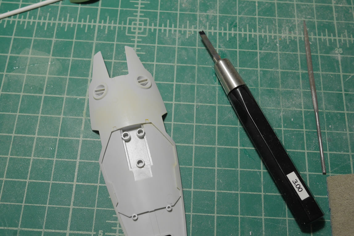
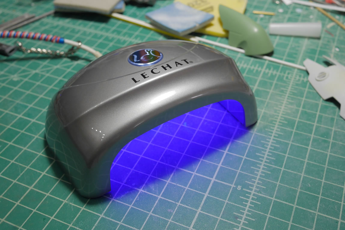
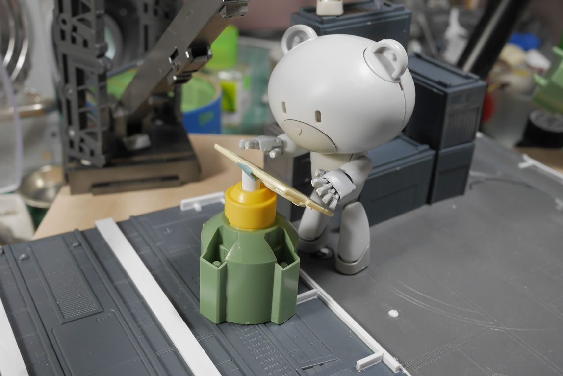
The demo below is with a shield that I gouged out a chunk of plastic with a scriber. Then applied the product, and placed it under a UV light to cure for about 30 seconds to a minute and the stuff is instantly sandable and solid. Pretty cool stuff for some quick filling.
Once sanded and primed, the gouge is now gone. So here’s another product to add to the list of tools for quicker building.
I also did a quick live broadcast on this too and made comparison with some of the other putty products I use.
Now back to the bear guy after that quick commercial break. The backpack is finally cleaned up. The problem with scratch building and kitbashing is the clean up work for all the glued and puttied areas. This part must have gone through 3 or 4 priming, sanding, and filling session. Now it is finally ready for some paint.
Returning to the lower torso Ball part and the vents. I glued the vents into position and then need to meld this to the Ball. I had originally cut away the original engine cover armor. Now with the vent in place, it is time to modify the cutaway area and glue it back into position to recreate the engine cover armor. I also added in some armor as a shield over the lower area of the vents. I think this helps creates the effect that the vents are inside the armor and the cutouts are designed to help the venting. Then more styrene filler to close up the gaps.
While the work on the lower toros continues, the upper torso pieces are painted.
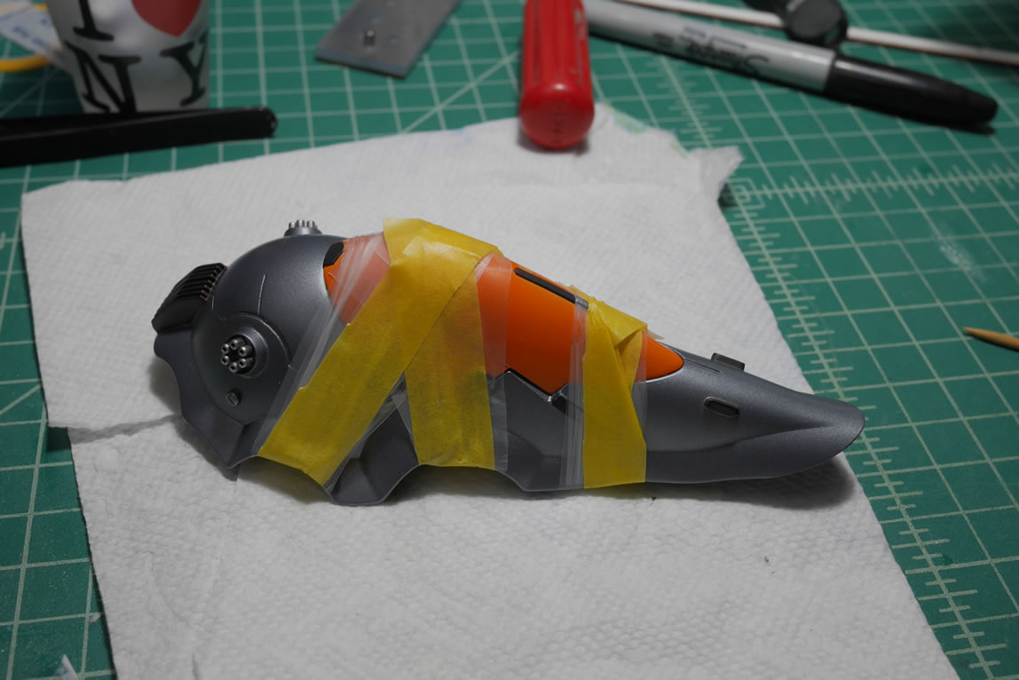
With most scratch built/kitbashed projects, there is always masking involved. I’m not about to spend time to design things like bandai so that I can have separate parts to paint that are easily assembled. In my world, everything is glued and puttied. So masking is a necessary evil. The thruster bells are painted on the inside first, masked with sticky tack then the outer bells are painted. THe control panel is painted in alclad dark aluminum then masked off to paint the frame black.
The internals are painted with alclad burnt metal and the exterior painted with stainless steel and a quick splash of hot metal septia for tone work.
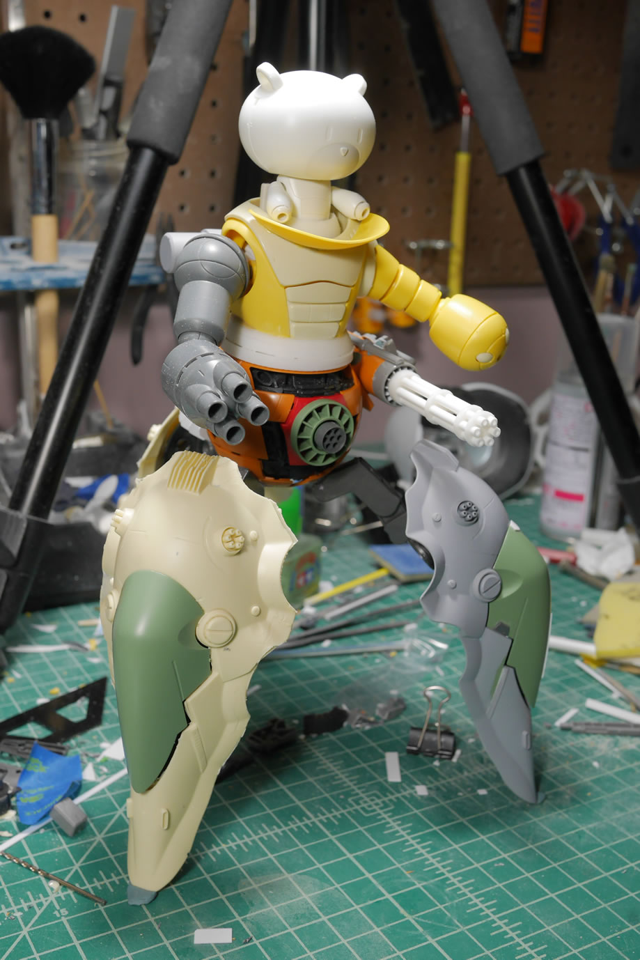
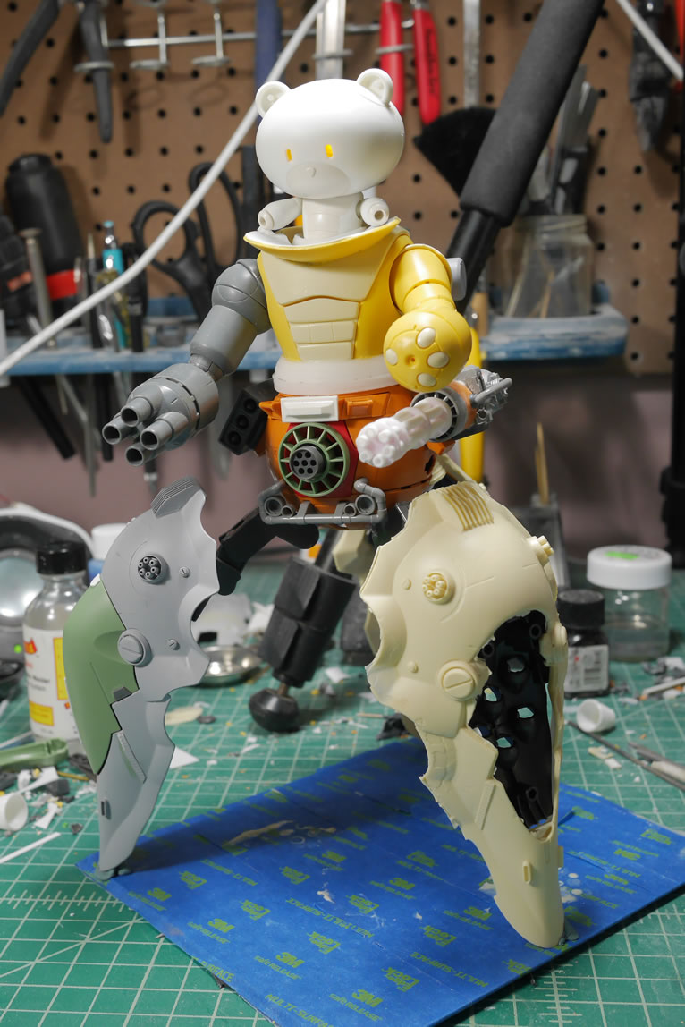
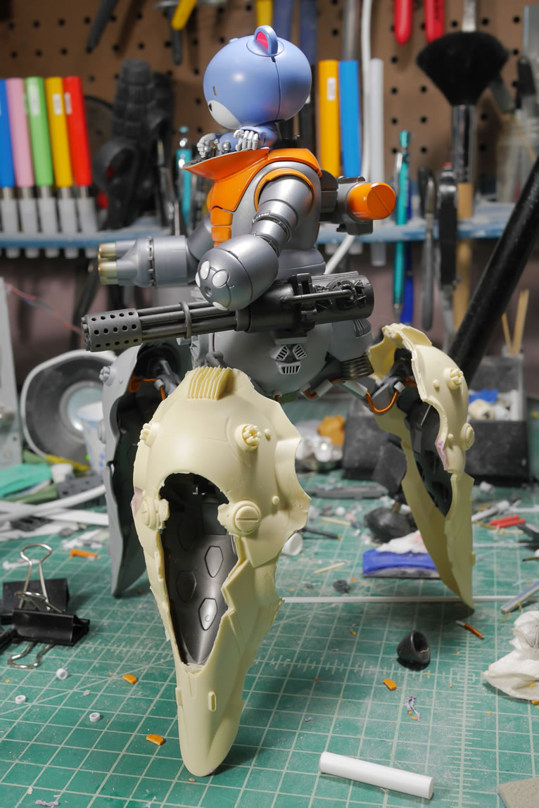
Here is a quick mock up for the upper torso since most of the upper torso’s paint is almost complete. Note that I made a slight change to the lower torso’s mounted gatling gun. I’ve been taking an intro zbrush class and made a quick A-10 style gatling gun barrel end. I have the original barrel painted as well, and the barrel assemblies can be interchanged like the hands. I think this make the gun look a little beefier and meaner.
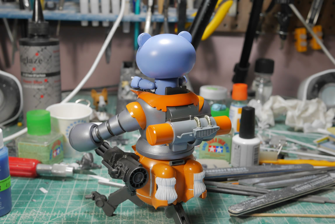
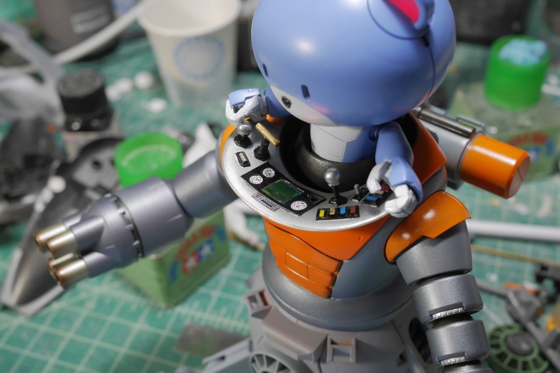
Here are a couple of top views with the control panel. I still have lots of detail painting for the control panel before I can call that part done. But it’s progressing. I can now focus on the lower torso.
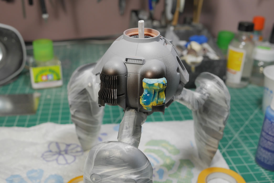
Returning to the lower torso, the last bits of work I did last night was to putty over the pane lines on the ball. The upper torso doesn’t have too many panel lines so I figured this would help mesh things together. Once I prime this, and do a visual mockup, I will know where to add back panel lines while keeping the whole thing looking like cohesive design as opposed to slapping things together and having things mismatched or just stand out. Primer and paint help a great deal in meshing things together. But small details are really the key to a cohesive design and tying everything together.
June 26, 2018: June update for this project. As of this posting, the main kit for the project is done. I’m just playing catchup with the progress for what happened between the last update and last week’s final assembly and photo session. I took all these pictures during the build so why not post up the progress. Last we left off, I had just applied a ton of putty all over the lower body. The gaps and some panel lines are getting filled. Once the putty is dry, its off to sanding the whole section. In addition of the putty, I used some of the UV gel product to quickly fill small areas. Not pictured in the first set is the initial primed kit after all the sanding. Pictured is the part after sanding the initial layer of primer.
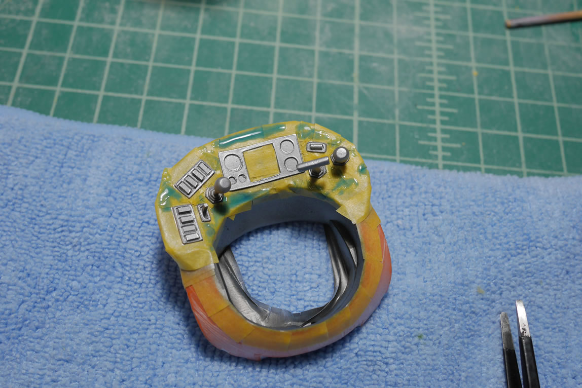
Returning to the upper torso, I now have the control panel getting painted. The last updated had the beginnings of painting this area. I hand painted in the button colors. Once the paint is dried, I sprayed a clear gloss because I wanted to add some water slide decals for the dials. The center screen is color shifting iridescent stickers from HiQ, so different angles will give a different color reflection. It works well enough as a screen for the control panel. I also did a quick mock up with the upper torso and the primed lower torso.
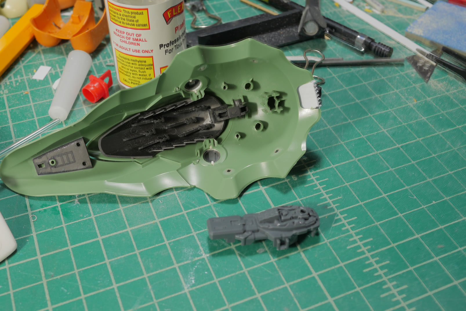
I had glued the leg joints a month ago, so now that I got the lower torso surfaced prepped and ready for paint, I can glue in the leg frames – which are the inner frames from the kshatriya binders. The kit came with 2 different sets of frames, one for the newer design of the opening binder and the original design for the non opening binder. Since I decided against having the binders open, I’m just going to use the original design for the rear leg. I will need to make some fixes to balance this part with the two front leg frames. Once glued, there is some mobility with the joints.
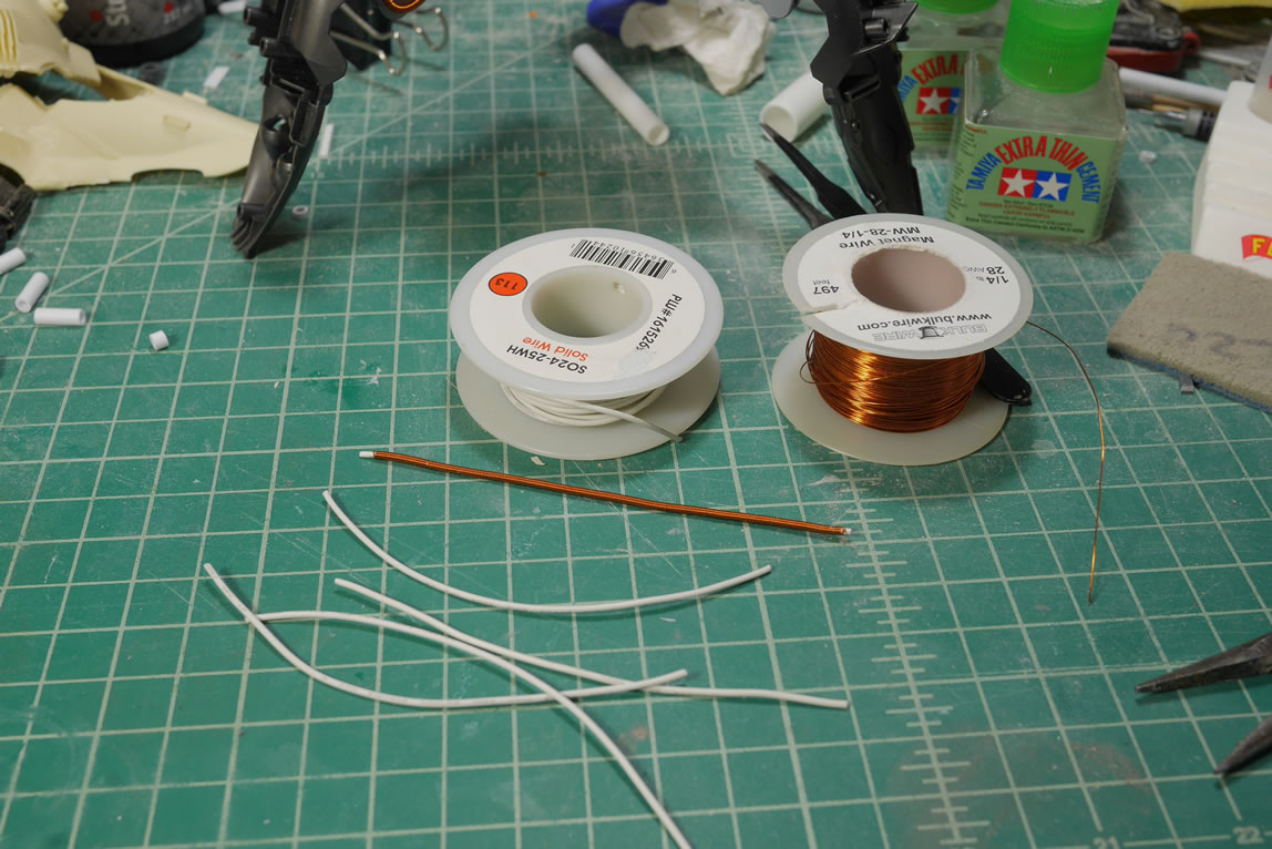
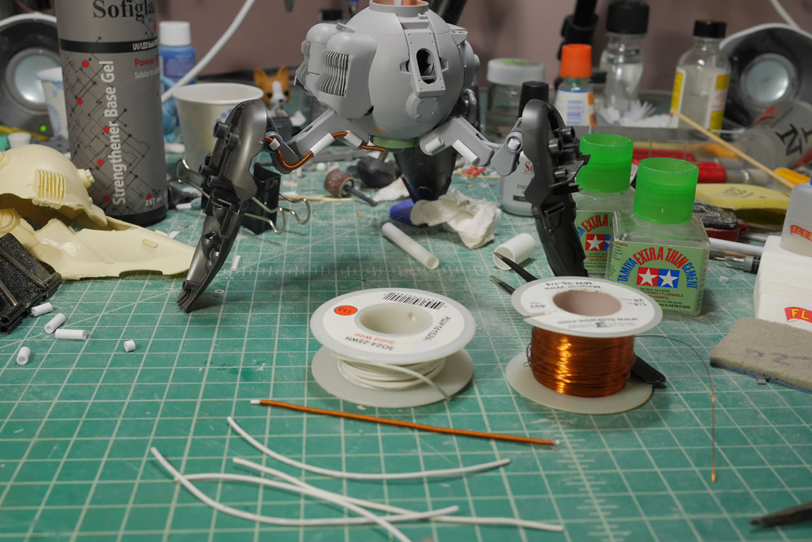
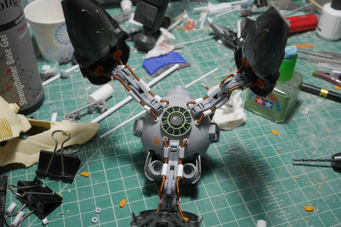
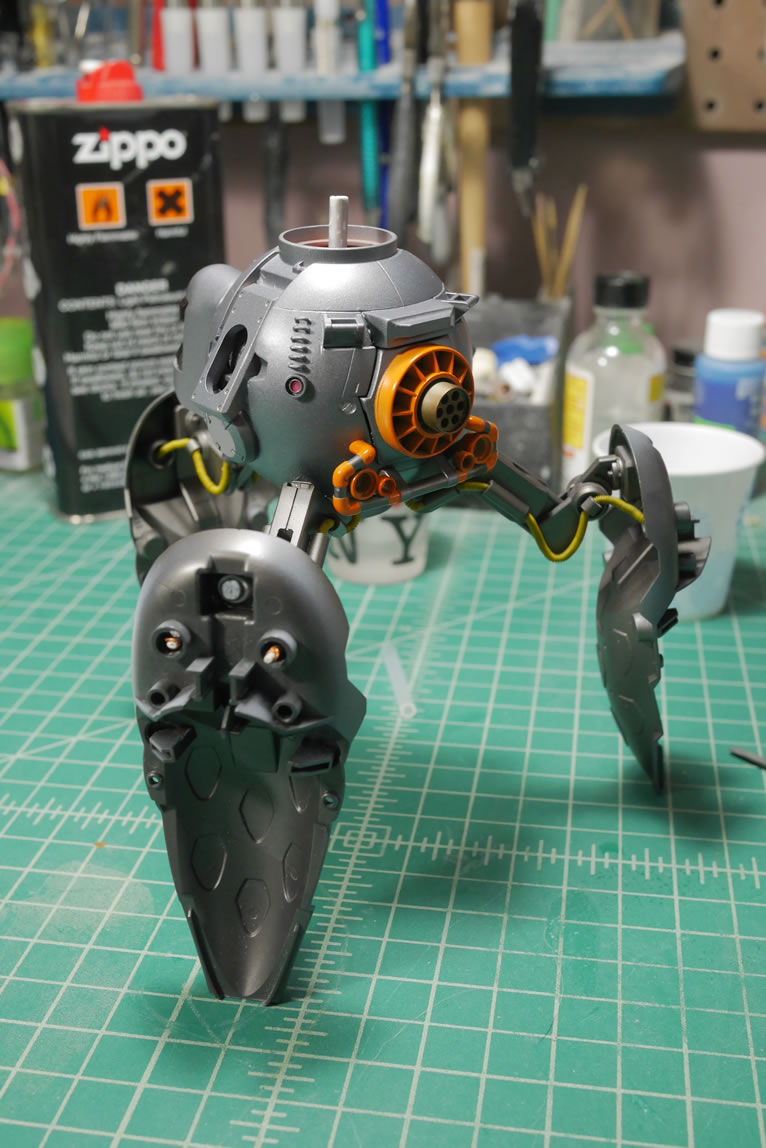
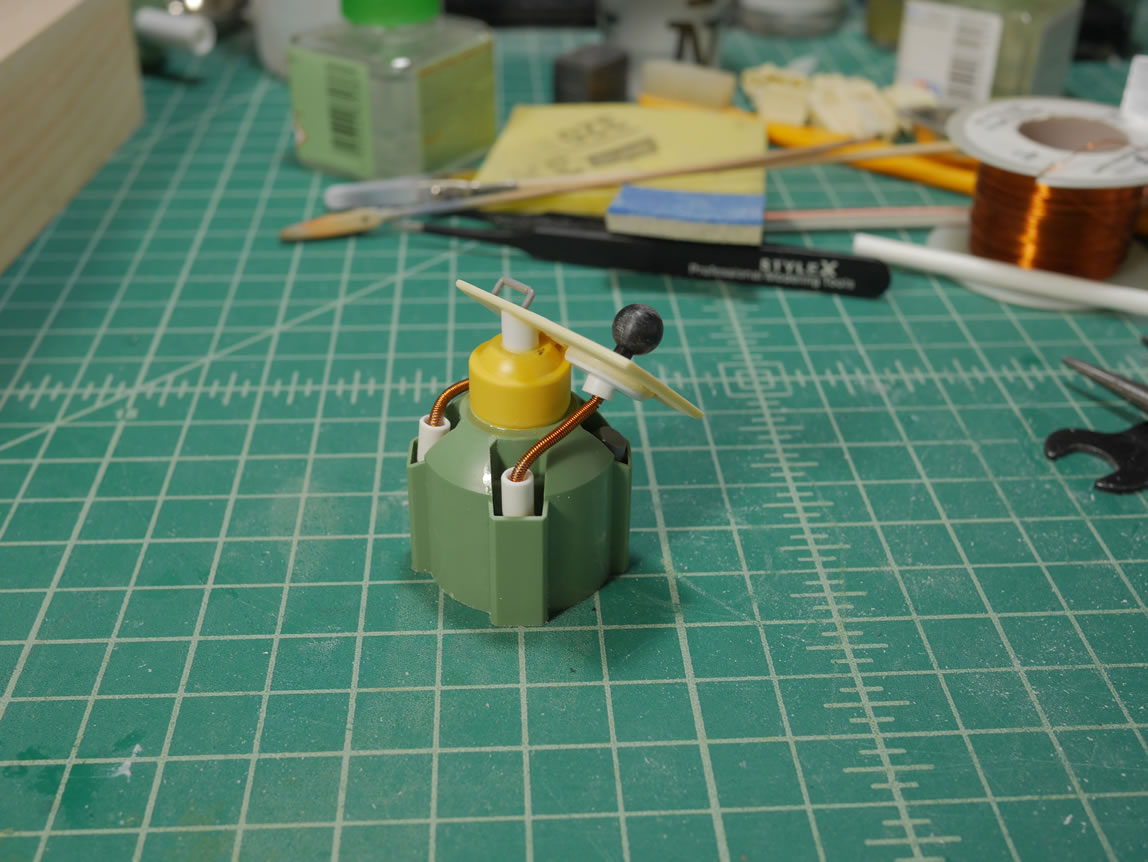
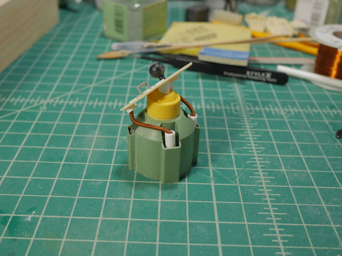
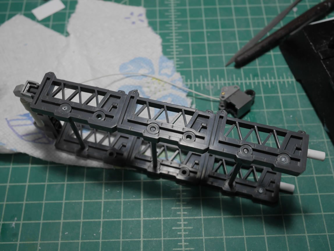
Now that I have the leg frames glued, I need to add some details, so I grabbed some 24 awg solid wrapped wire and the 28 awg magnet wire and made some coils to run from the leg frame to the lower body along the leg joints parts. Making the coils is simple, just wrap the magnet wire around the solid wire and done. There’s a quick test fit for length and the rough look and feel before moving on to the next step. Styrene tubes are cut and glued to the leg joints. The coil is then threaded through these tubes to connect up the leg frame and the lower body.
The plan is solid, so time for execution. Measurements on the leg joints are marked off with pencil as this will guide the tube gluing locations. The tubes are glued and another quick mock up with the binders connected to see how everything fits. It is always important to keep testing fitting as you build because the smallest of changes will seriously mess with the proportions and how well things fit together.
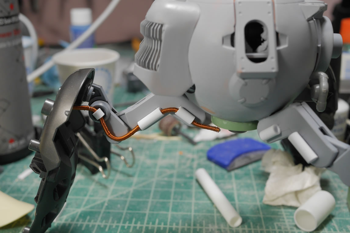
The coils are then threaded once the glue has cured overnight. I need a transition piece for the lower body so some more styrene tubes are cut and glued to the body and then the coils can have a termination end. Another transition piece is made from the Kshatriya’s thrusters.
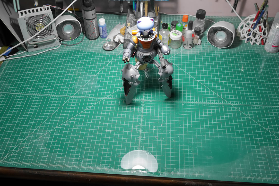
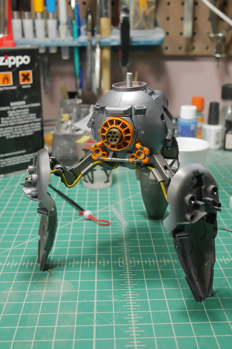
Time for some more test fits with the binders. The upper torso is pretty much done at this point. I’ve been procrastinating the binder work because there is a considerable amount of work to clean up the two resin casts.
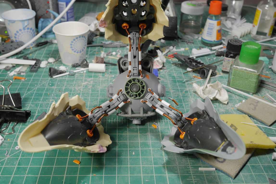
Here’s what the bottom of the kit looks like with the cables and transition partes all glued together.
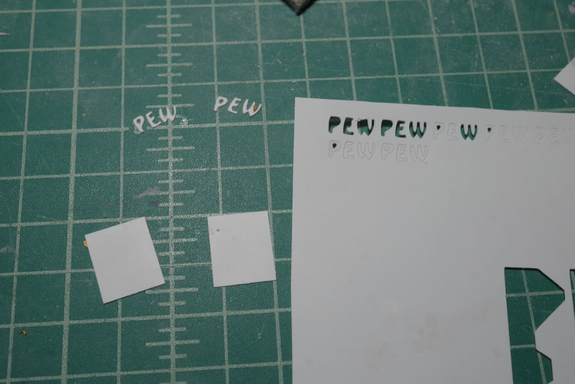
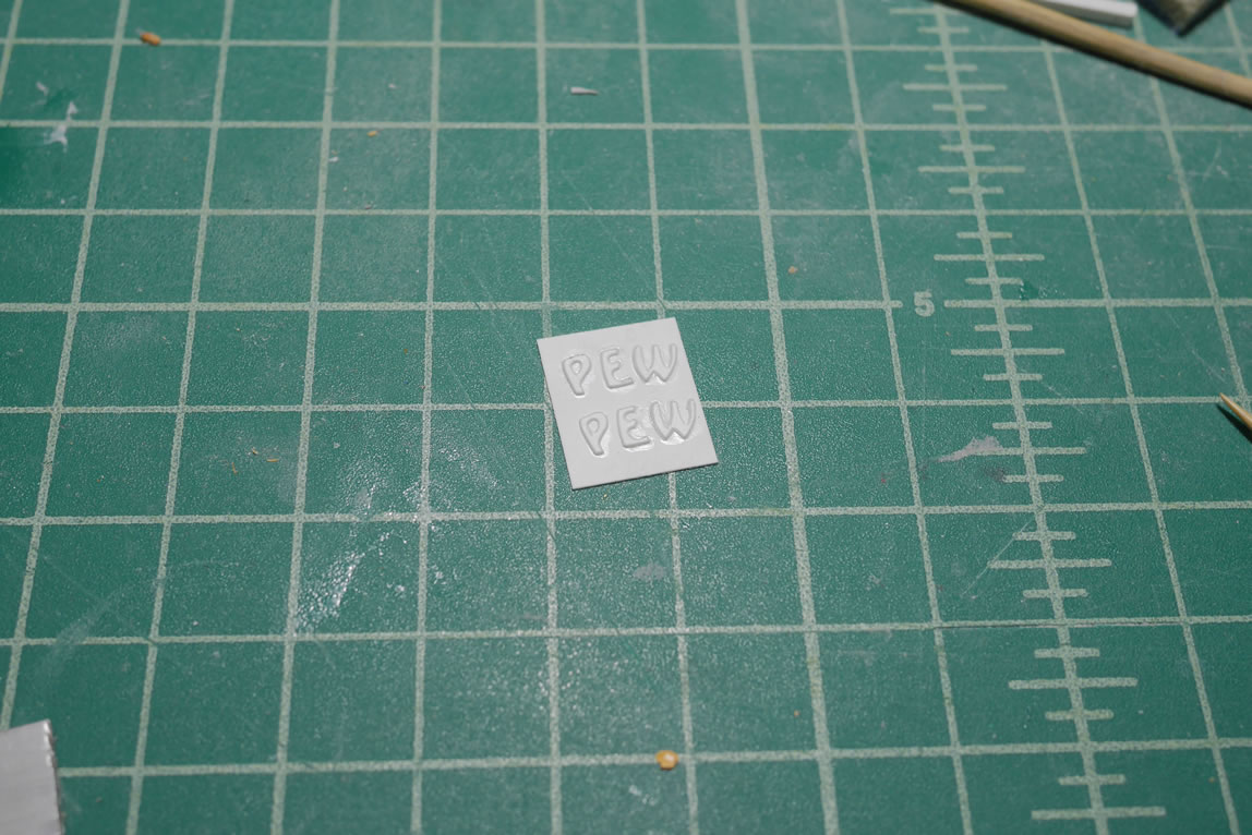
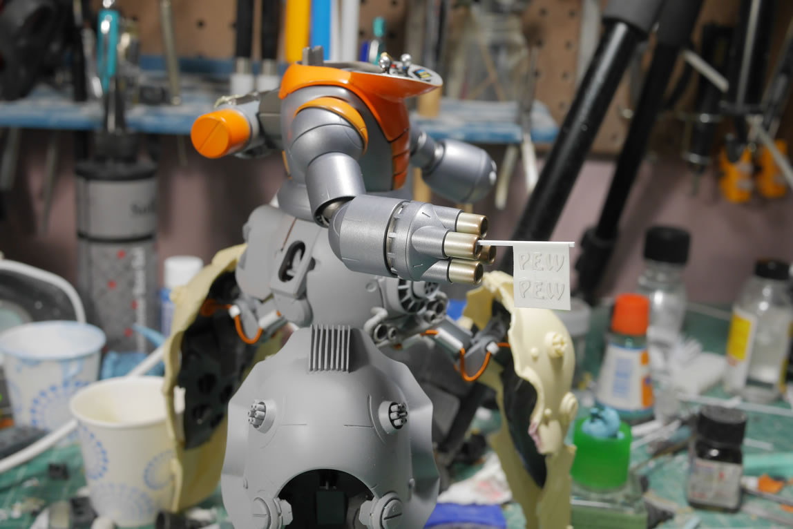
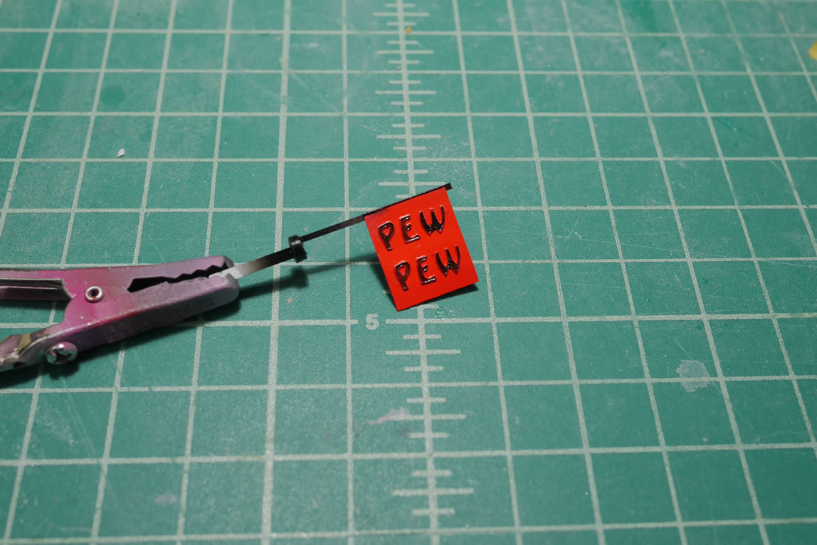
Since I’m going for the cute yet deadly angle, I figured I could up it a level with a “pew pew” sign. I picked out a font I liked and used the cricut to cut some letters out. These letters were then glued to a thin sheet of styrene that will be the pew pew flag. I bent the plastic a little to create a slight wave. Then did a test fit with the guntank barrel. I printed a few of the pew pews as I was going to use multiple flags, but I figured that one flag got the point across.
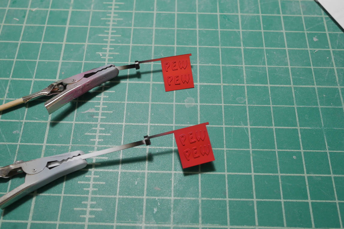
The flag get painted and the lettering is painted by hand with enamels. The letters are raised so this is easy to do. As one of my fellow TGG guys pointed out, the raised letters on a flag make no sense… but then again, what part of this whole kit makes sense? So it all goes to the nonsense of it all.
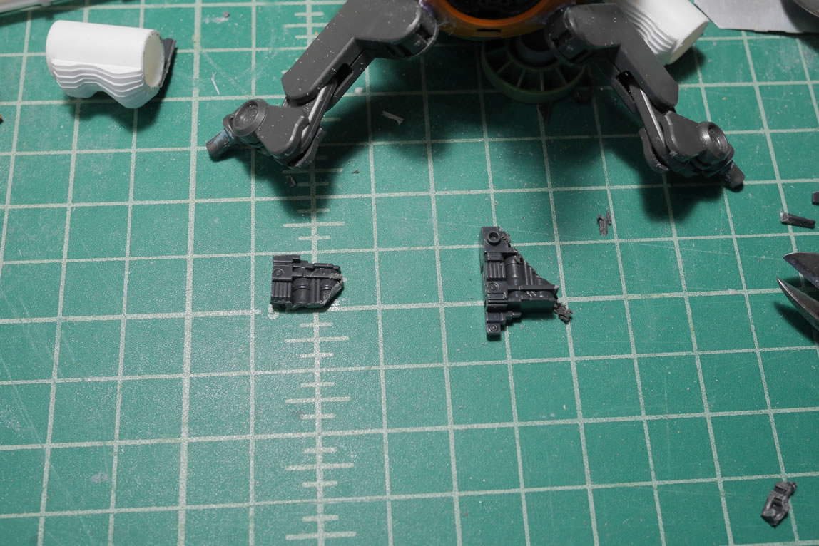
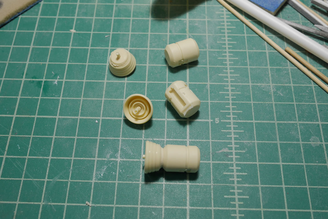
I casted some thruster bells from a previous project. Reusing molds is a great money saver. I also casted a part from the ore gun. These parts will eventually be the thruster and engine attached at the bottom of the binders. The side of the lower body got some detail work. I created a little ladder with those heavy user parts that came with the first MGs (Zaku/Gundam) Back when the MGs first came out, these kits also came with added details that were labeled “heavy user parts”. These were rarely used since they required glue. So I think Bandai abandoned this pretty damn quickly. It’s a shame because us more hardcore model builders loves these little details. It’s one less thing we would need to scratch. Another round mold was added at the bottom completed this detail.
Next up, the rear binder leg’s frame gets some styrene plates glued into place where the funnels attach. The new design has these closed up and to sorta keep everything looking similar; the styrene covers are glued into place. The last photo is the paint-mask-paint process for the kit’s bar detail.
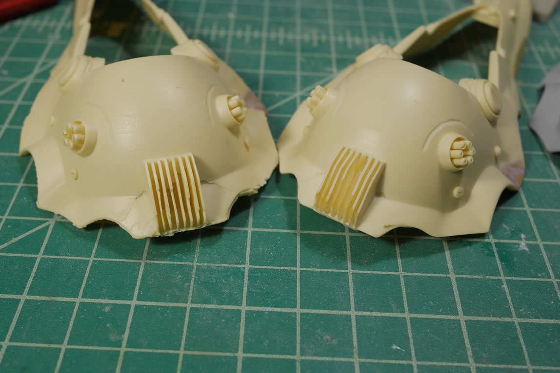
Now for the dreaded resin binder clean up work. Each of these binders took about 6 hours of work to clean up and fill. The process would have been much longer if I used traditional epoxy or styrene putties. I used light curing putty which significantly sped up the process. I can add the putty, throw it under the UV lamp, sand, and continue. The heat sinks for the resin binders needed considerable rebuilding, so that was carefully done with light curing putty as well. The last picture shows a comparison with the repaired binder and yet to repair binder.
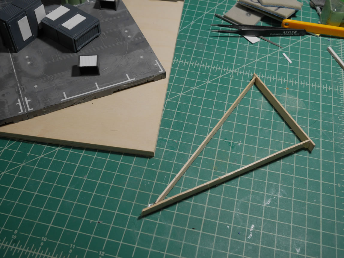
Having spent 6 hours working on one binder, I got a little burnt out so time for some fun work. I decided to create a little display base for the kit. First up was to use the pirate parts I jokingly made to create just a pirate petit guy. Using some left over sprue and a small thruster bell, I created a peg leg. I scribbed some lines into the leg to get some wood texture that should look decent after it’s painted and washed appropriately. I also lay out the basics of the base on the wood board. I will be cutting up the plastic so this is just the design phase. I have 4 petit guys for this, so each head gets it’s own LED system and ear switch.
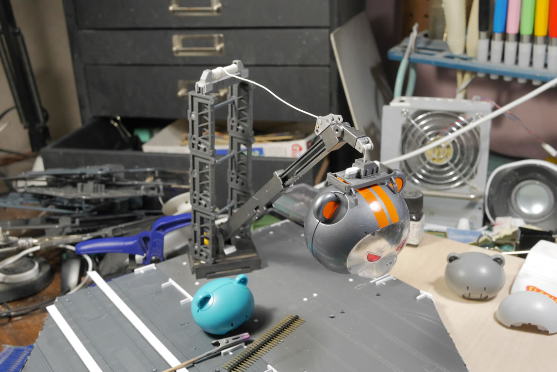
Since I had made the helmet, I wanted a way to display both the petit in the driver seat as well as the helmet. My brainstorming brought me to the idea of a petit guy hanger. Pirate guy would be directing things as the old salty veteran that’s already lost appendages in previous battles. The narrative now puts the pilot I built as just a testing guy. The real pilot will be painted in the same scheme as the main kit and be standing aside while the helmet is getting lowered. This allows the display of the helmet. For this, I slapped together some parts and created a crane to hold the helmet. The helmet is connected to the crane via magnets so it can be removed and actually used on the blue pilot. Then comes a very rough mock up of how everything will look. With a crane in the scene, I need a crane operator and a control panel. The other kit will just be under the kit doing inspection work. This is how the scene plays out in my head; I just need to execute it… later. Break time is over and I need to finish the other binder.
And we jump right into primed and ready to paint binders. The desk is cleaned from all the construction work.
There are some minor fixes for the binders after the priming. And those are fixed relatively easily; so only a few sessions of prime-sand-putty-sand-prime.
The lower body gets some paint. I painted alclad exhaust manifold for the heat sinks for the body’s thrusters. This is then masked so the rest of the lower body can be painted. Details for the binders are painted and masked off.
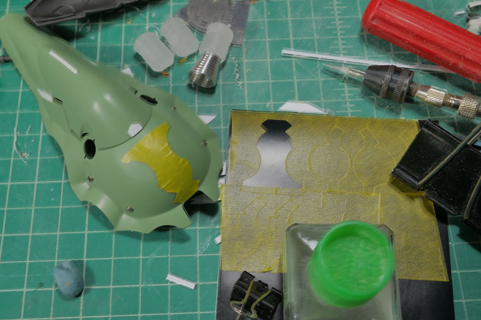
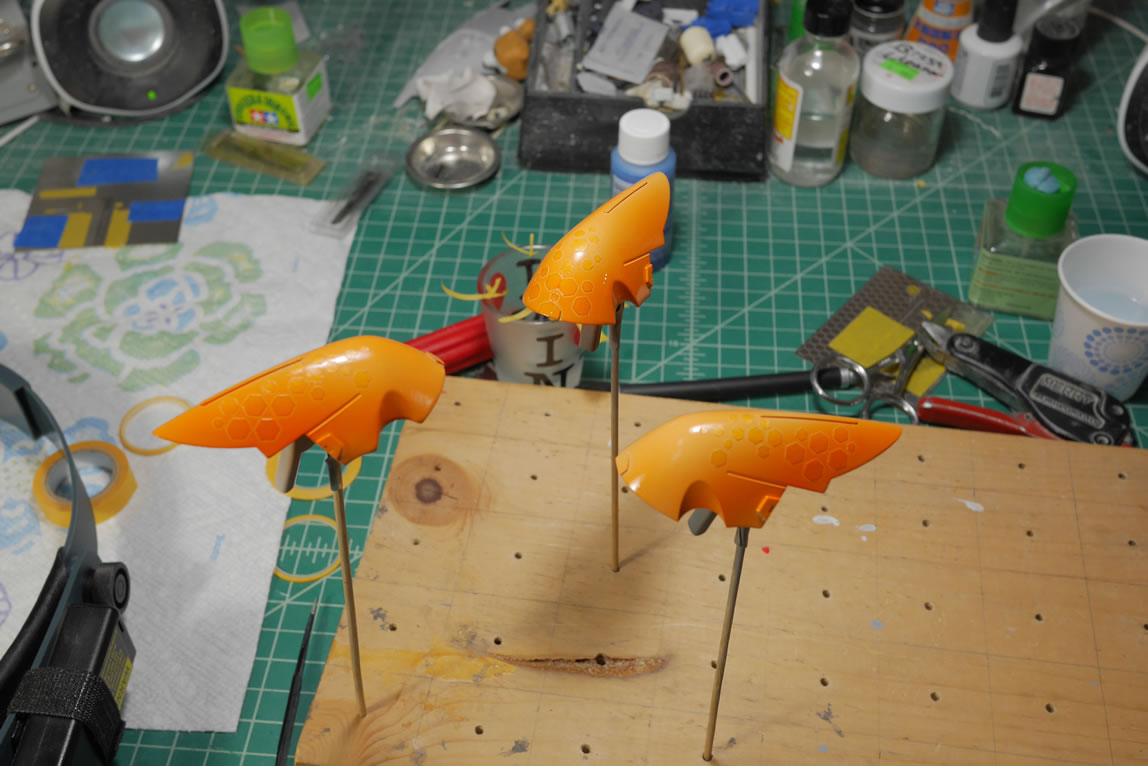
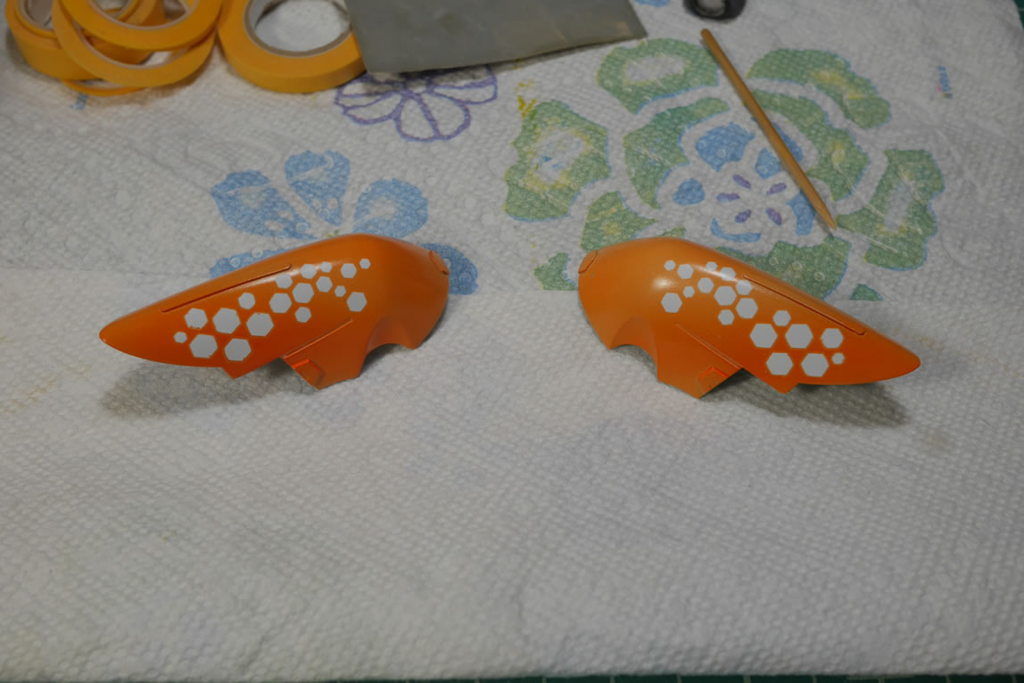
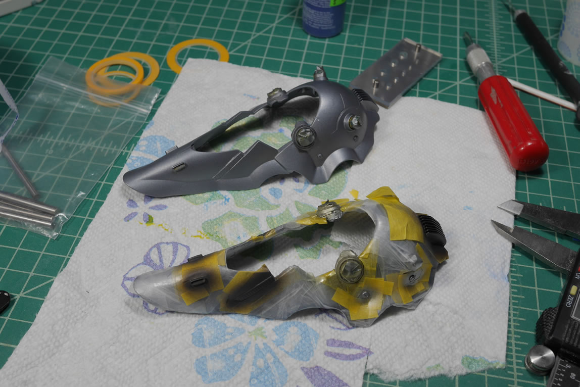
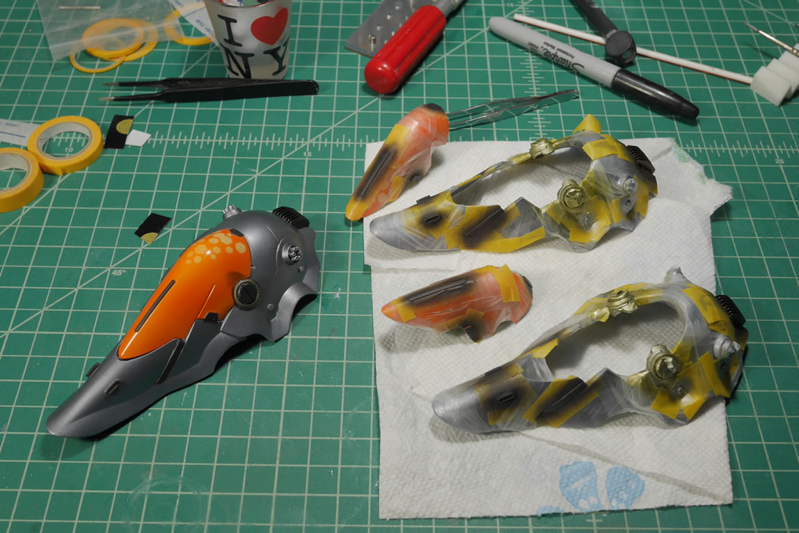
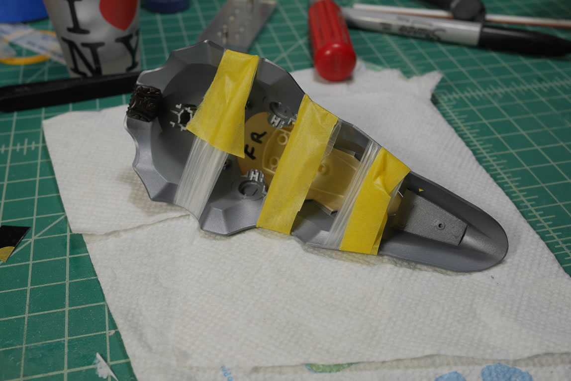
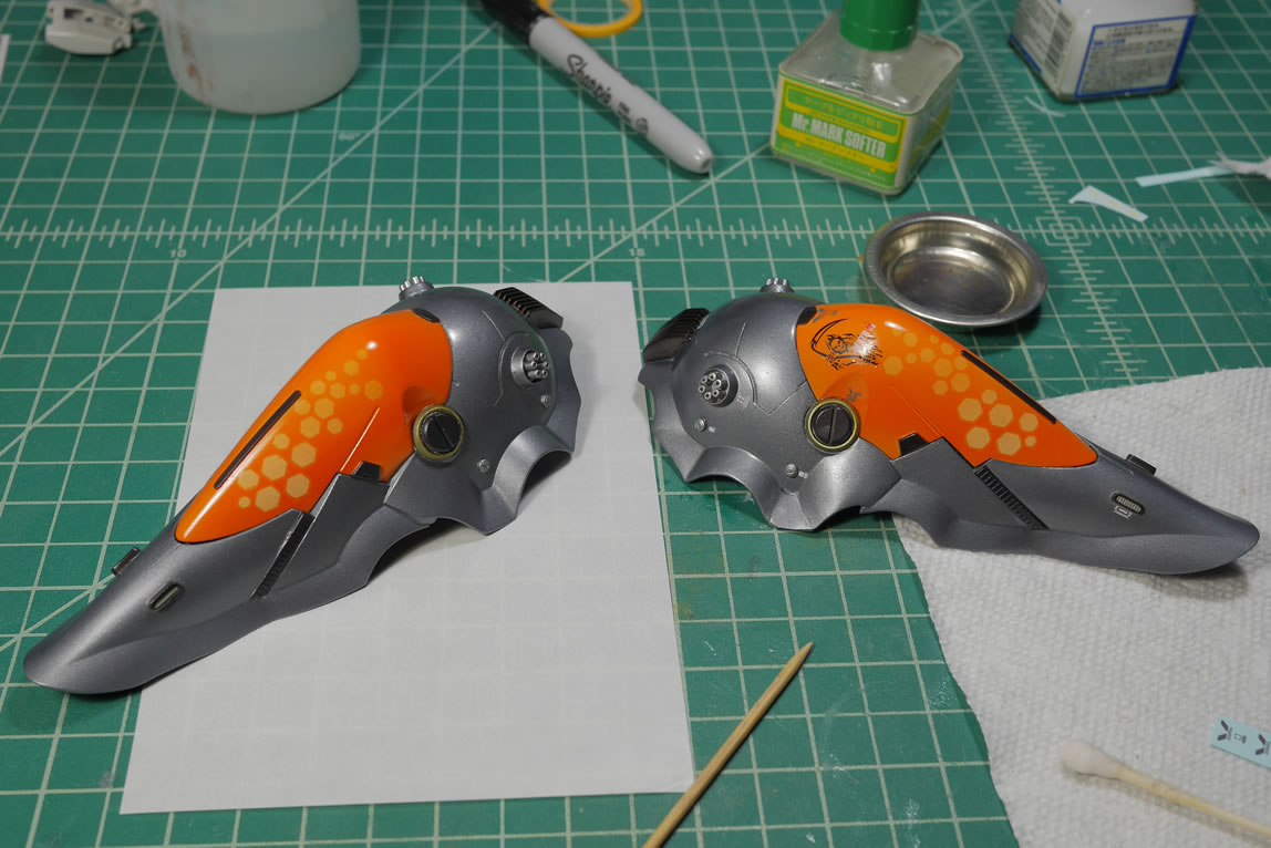
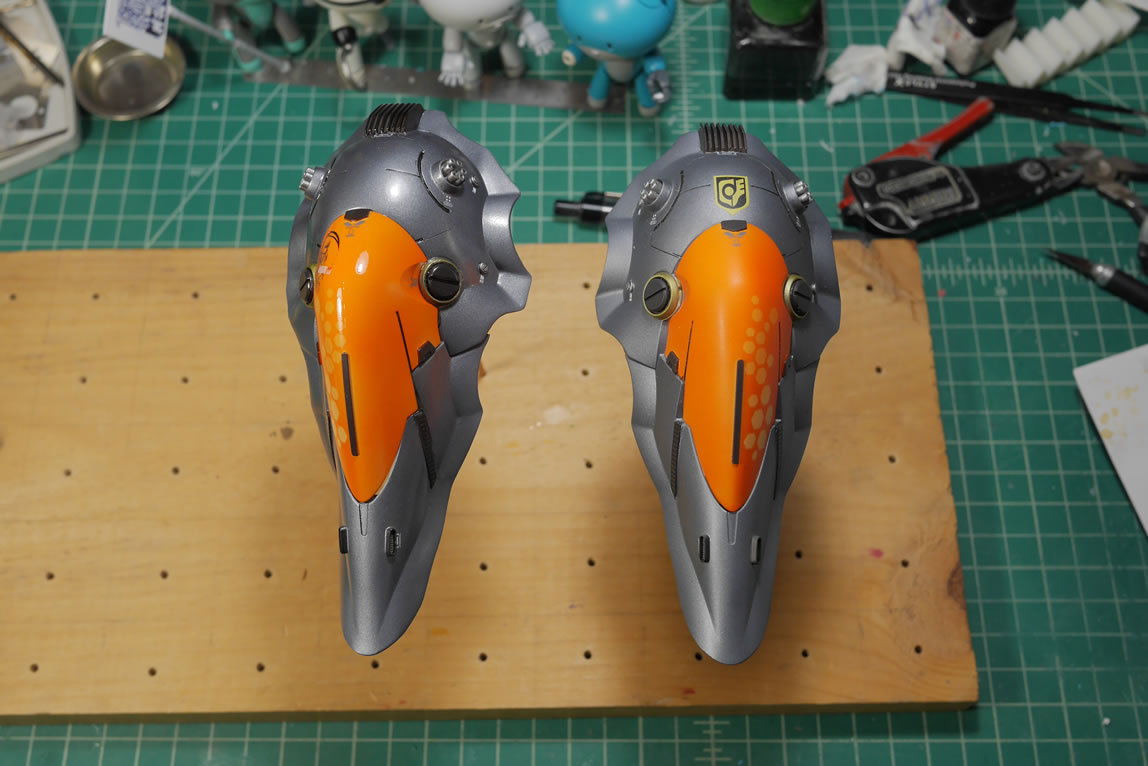
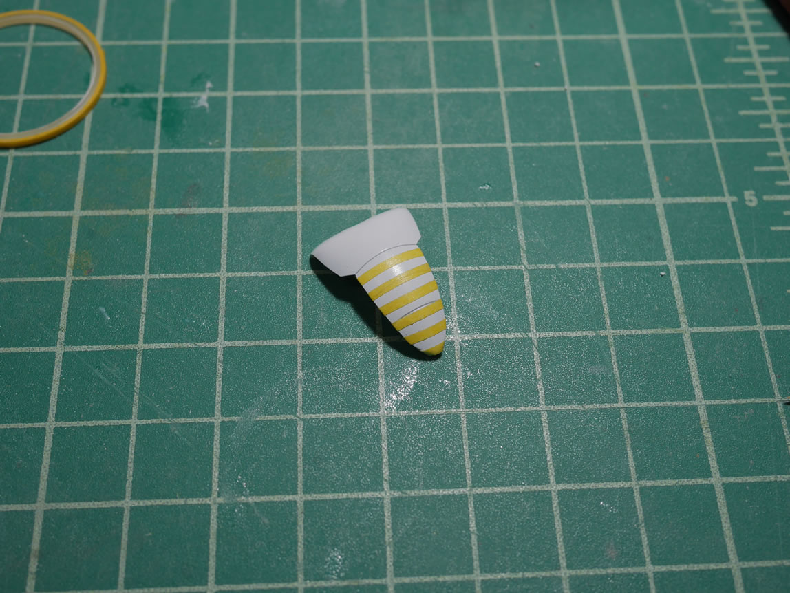
While all the above are at various stages of drying/curing, time to move onto the top of the binders. I start with painting them white, as I will be painting these with clear orange as I have with the other orange parts. Prior to the clear orange, I want to do some hex masking. I did a quick video broadcast about this step and it can be seen here:
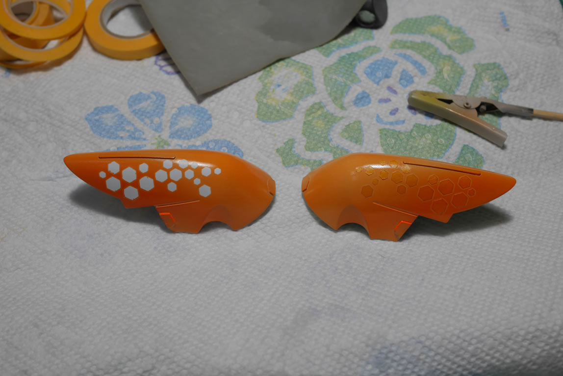
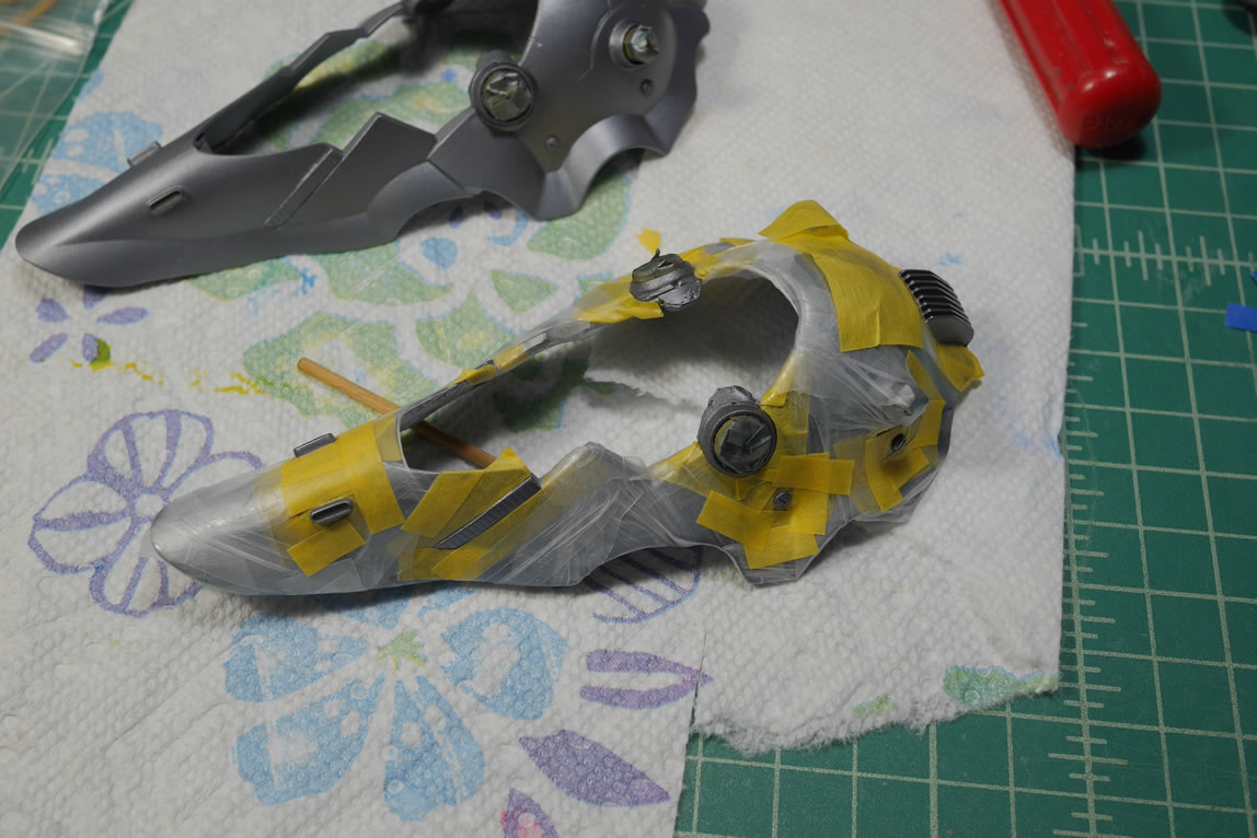
The hexes are cut with the cricut and the parts are masked. I use some other tape as guides since I will need to reproduce the masking scheme on the other parts.
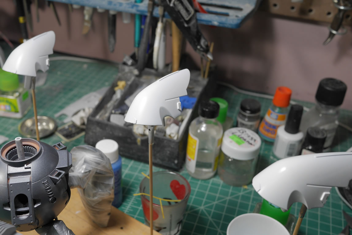
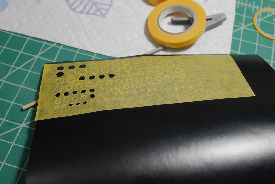
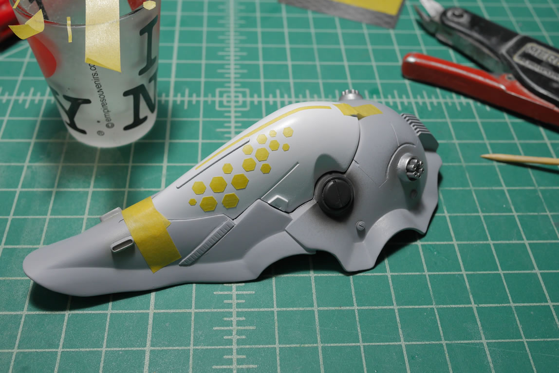
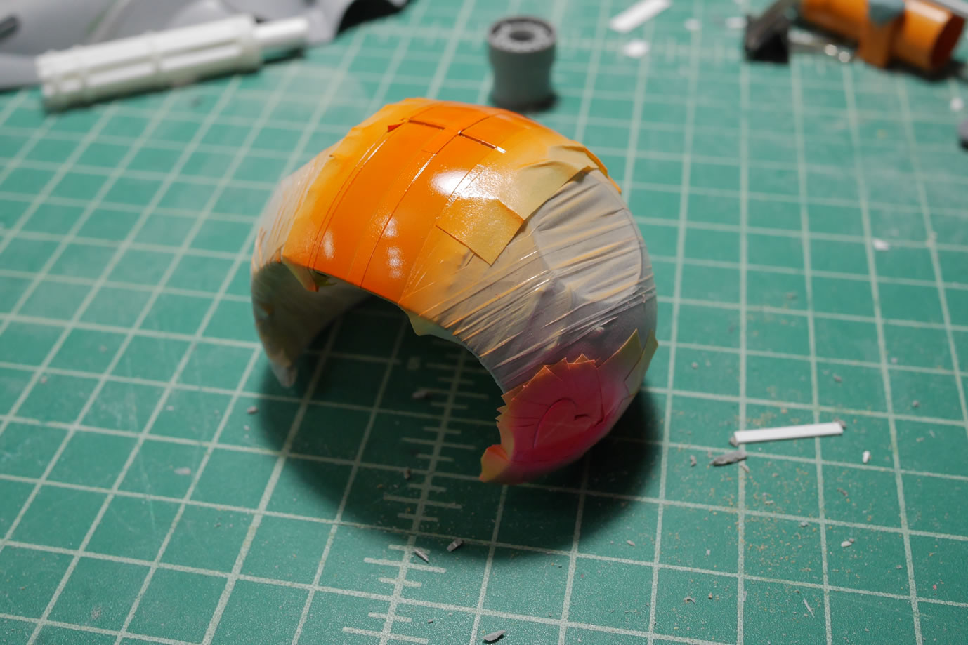
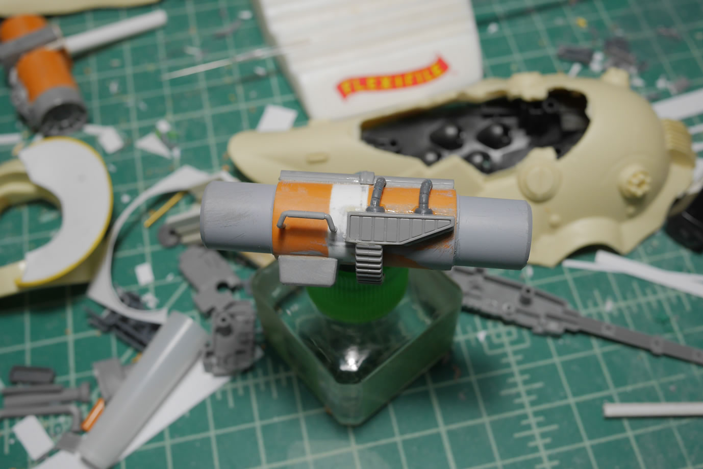
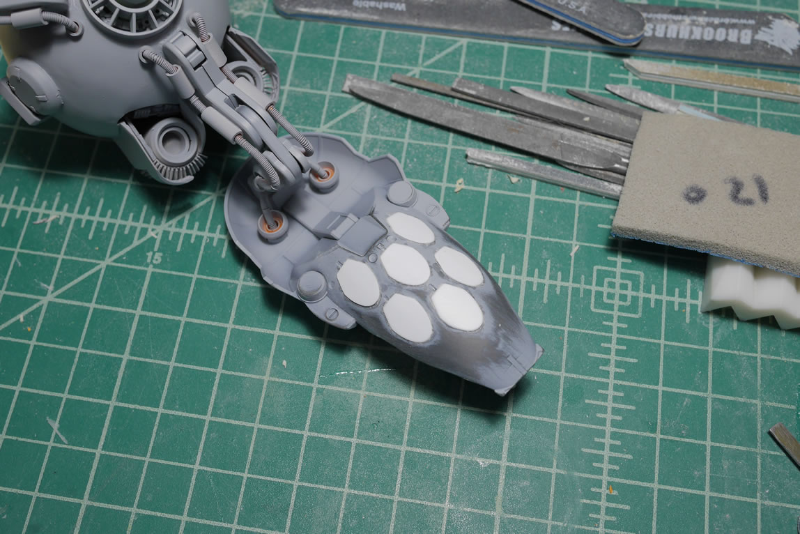
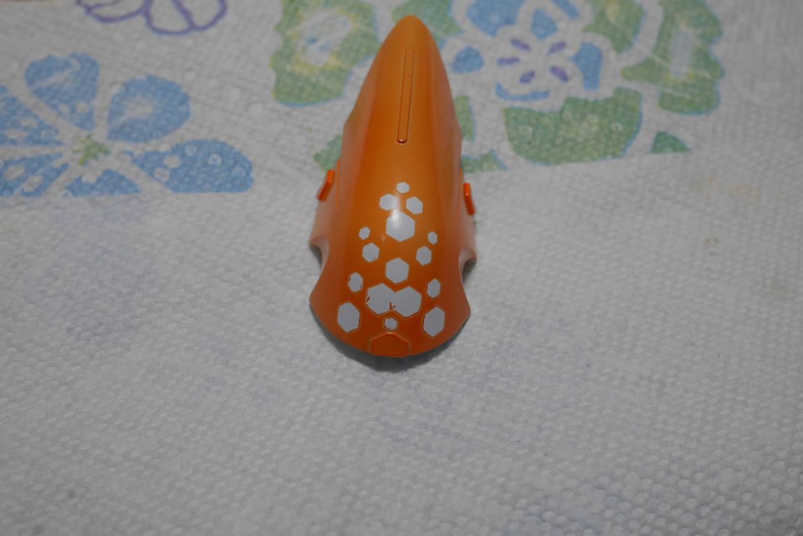
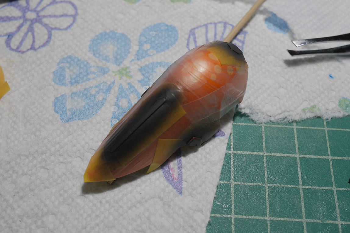
Once the masking is done; clear orange is painted. The application of the clear orange is controlled so that the lower areas of the parts get a heaver coat than the top area. This is planned because I want to do a fade technique on the masked areas. This will make a little more sense as I progress. Looking at the pictures there is a tonal difference from the top area to the lower areas where the masking is placed.
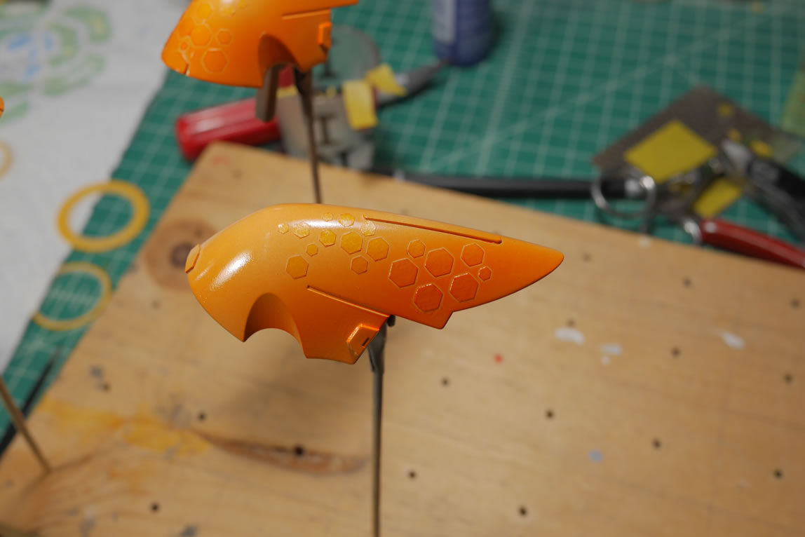
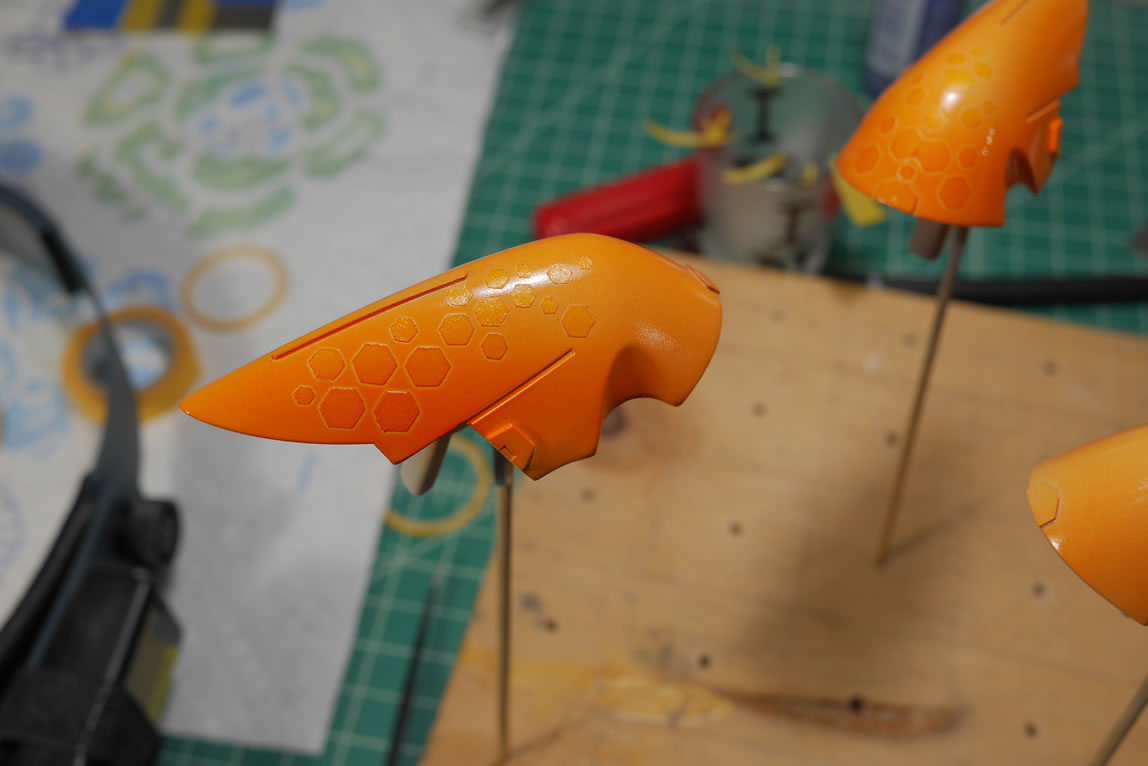
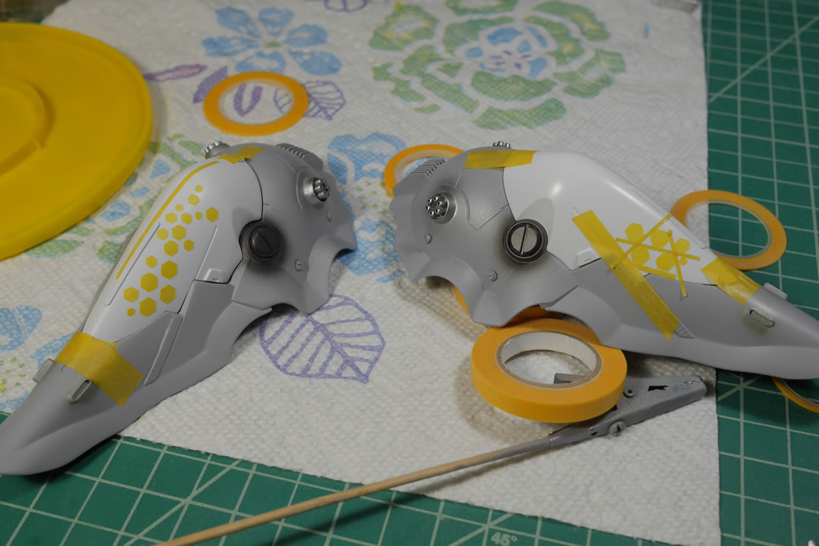
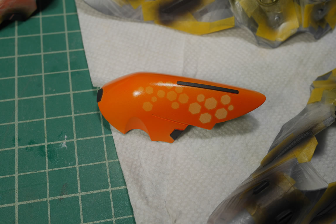
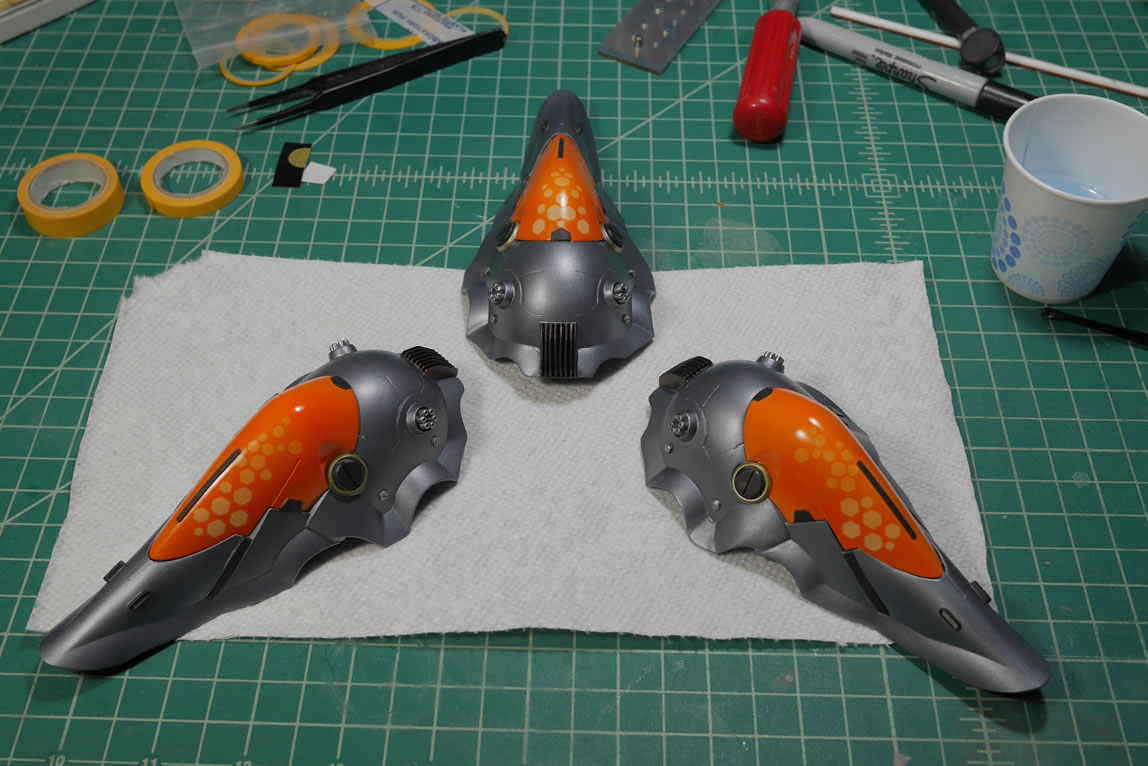
Masking hexes are removed after a full day’s cure. There are some rough spots where paint leaked, these were cleaned up slightly with some very high grit sanding pads/meshes. 4000 and 3600 grit pads/meshes were used.
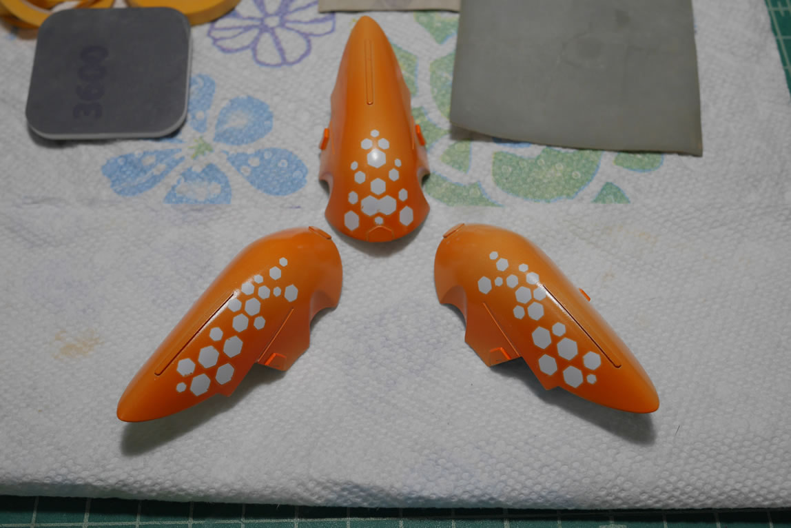
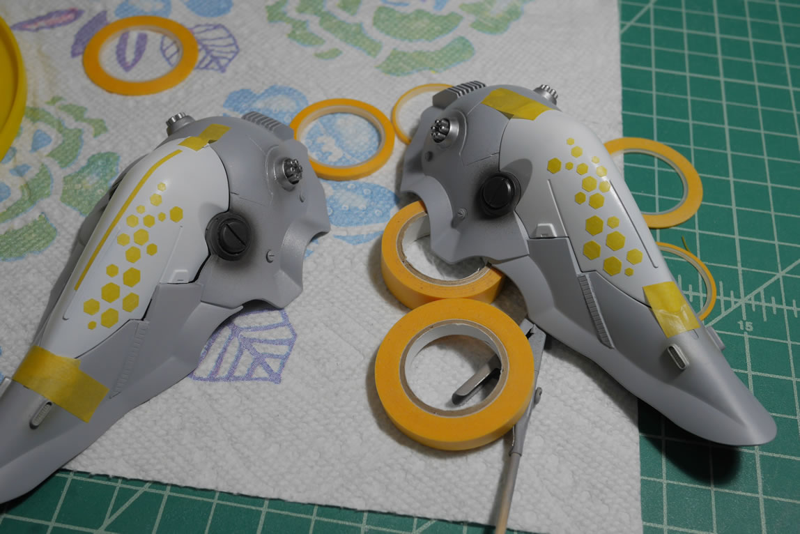
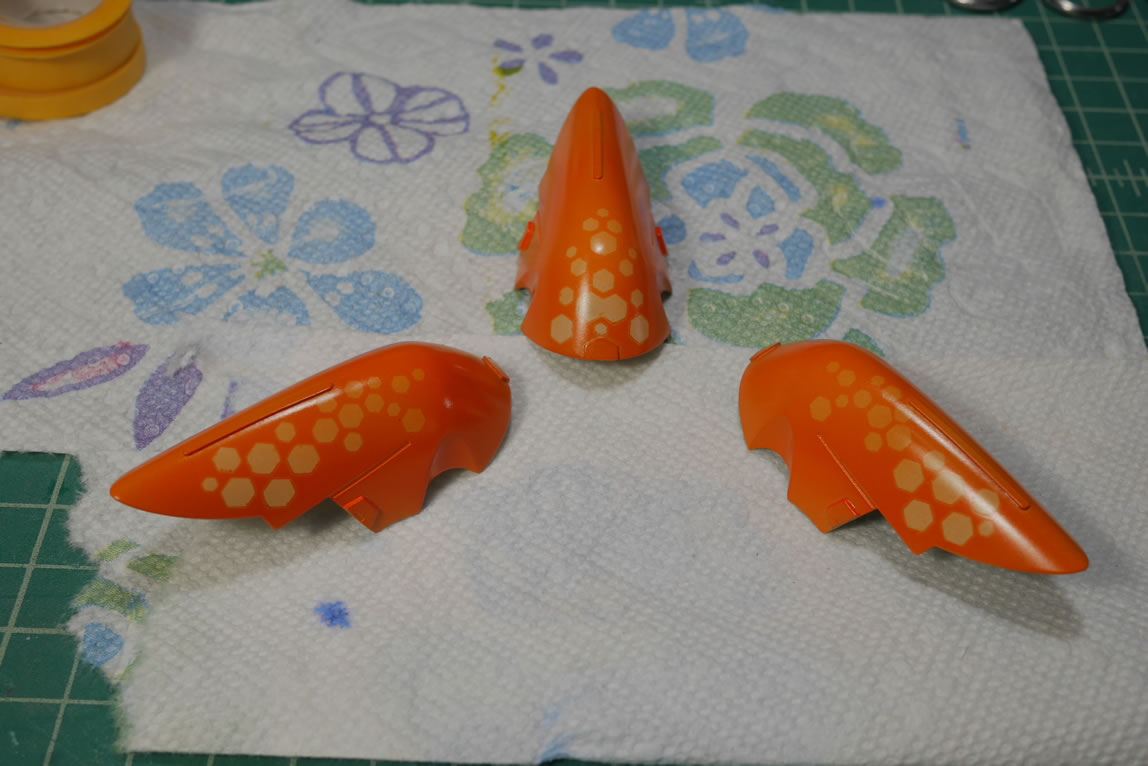
The kit is unmasked and cleaned up a little. Another layer of clear orange is sprayed concentrating on evening the tone of the top area with the bottom area and just leveling out the tone for the entire part. This effectively creates a fade for the masked off white parts being brighter at the top and fading with orange at the top.
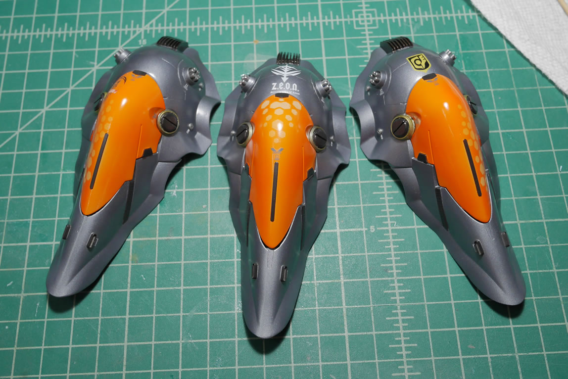
Back to the main binder parts. Earlier I painted the first layer of details. Those are masked off to paint in the main color for the binders. The same semi gloss bright gunmetal used earlier.

Once painted and cured for a day, I can get to masking off the main color to paint in the details. I use a punch to create masking templates for some of the circle details.
Hours later… one part is masked. Once I get one binder masked, I paint the detailed immediately. This is to avoid the low tack paint from lifting while I spend another couple of hours masking off the other binders.
The top part is also masked and details painted. Unmasking everything, I can put one of the binders together.
Now on to masking and painting the details on the other binders.
With resin pieces, you will get some interesting fit problems because they may warp slightly. For gluing the binder pieces together, I used some parafilm to give me a light hold then used masking tape over the parafilm to get a strong hold for the two parts that also ensures I don’t damage the paint. Once the parts are aligned, a little bit of epoxy glue is applied and the part is left to sit and cure. The same process is done to the other binders.
Returning to the lower body, all the painting is done and the cables were hand painted with an enamel zinc color to create a little contrast.
Everything is unmasked and cured for a day. A clear gloss is sprayed over everything to prepare the parts for the next step, deckals. Once decaled, the parts are left to cure for another day and another layer of clear gloss is sprayed to sandwich and protect the decals. This layer of clear also works to hide the decal edges.
The flat coat, well technically, the semi matte, is sprayed. I’m using alclad’s clear coats. They have 4 levels of clear. Gloss, semi gloss, semi matte, and matte that go from ultra shiny to not so shiny, to not so flat, to flat. At least, that’s how it’s supposed to look. I didn’t want a totally flat finish, as the metallic colors work with some bit of sheen so I went with a semi matte. Here are some comparisons between the glossy finish and the semi matte finish.
As I sprayed the semi matte on the lower body, I noticed that there were nubs that I missed. Better to discover them now than later when it’s on display somewhere… So time for a quick fix. The nubs were carefully sanded away and the parts are carefully re-painted. Pretty easy fix, but a fix that could have been avoided if I paid attention when I was building, sanding, priming, and all the other stages before this.
The parts are left to cure for another day. I will need to handle the parts to start glueing and assembling, so to avoid the potential finger print in uncured paint; I just let it sit.
Assembling the binders require some glue and a little light curing putty to fill some gaps. One of the parts have a bigger gap that needed to be filled with styrene.
Slowly and carefully, the kit is glued together and small areas fixed. The final thrusters and engines are glued to the tops of the binders to complete the kit. Now I just need to let the glue cure up, so the kit is moved to a safe space away from me.
To occupy my mind, I return to the display base work. The petitguy that will be under the main kit will need an inspection light. So I added an LED inside the arm and wired this through the connecting peg. From here, this is wired through to the head where I added another switch in the other ear and another battery pack. Since the LEDs in the eyes and the LED in the arm are different colors they run at different voltages which would draw differently from a single source battery. I would need to wire things up in parallel for such a system to work. So it was just easier for me to add in another battery inside the head. There’s plenty of room for it. Now I have two switches controlling two lights in this guy.
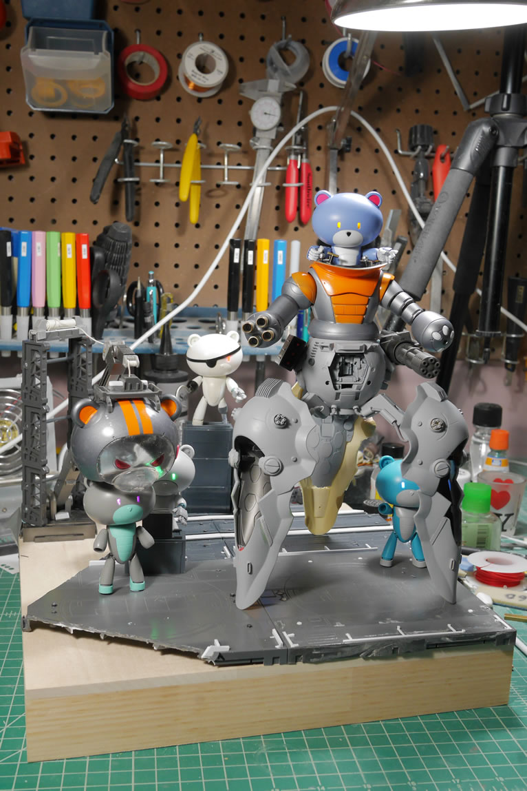
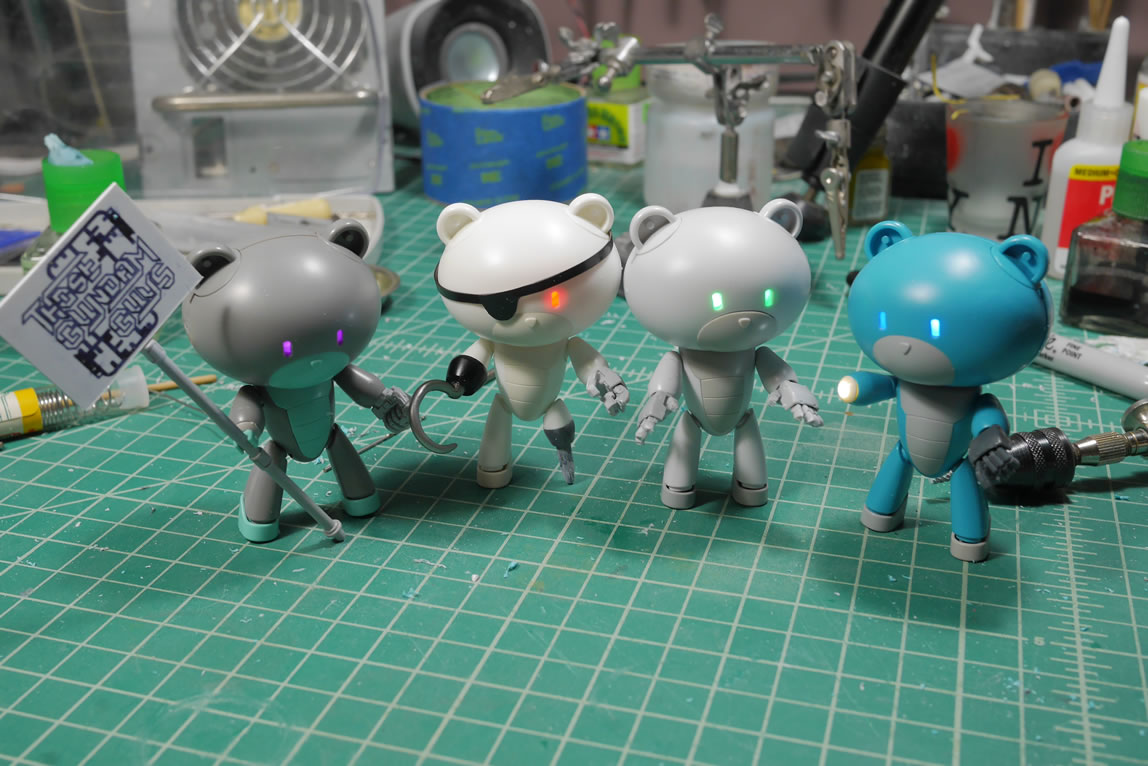
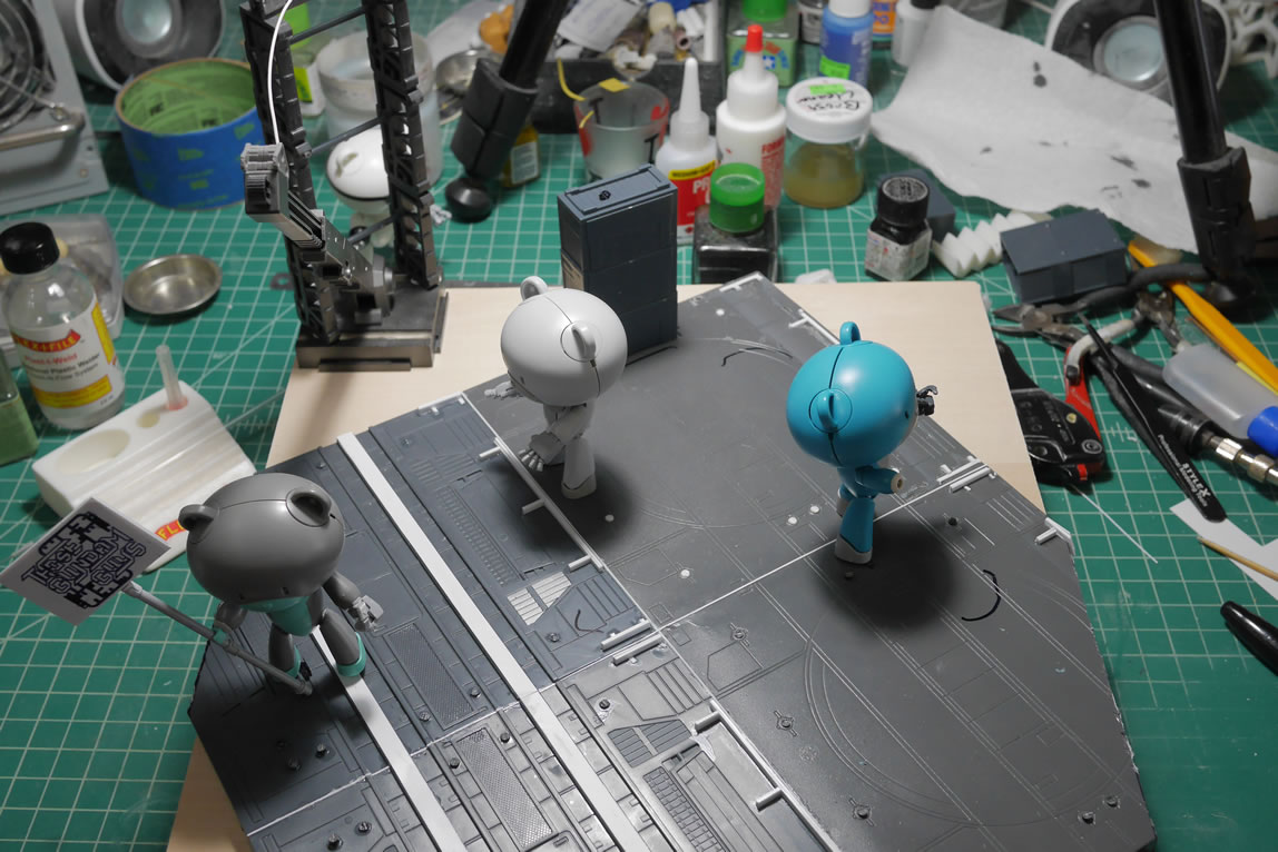
My squad of petits are ready for work. I added some magnets to the bottom of the feet so that I can just snap them into place and not have to worry about things falling over. Another quick test fit on the board finalizes the location of the squad.
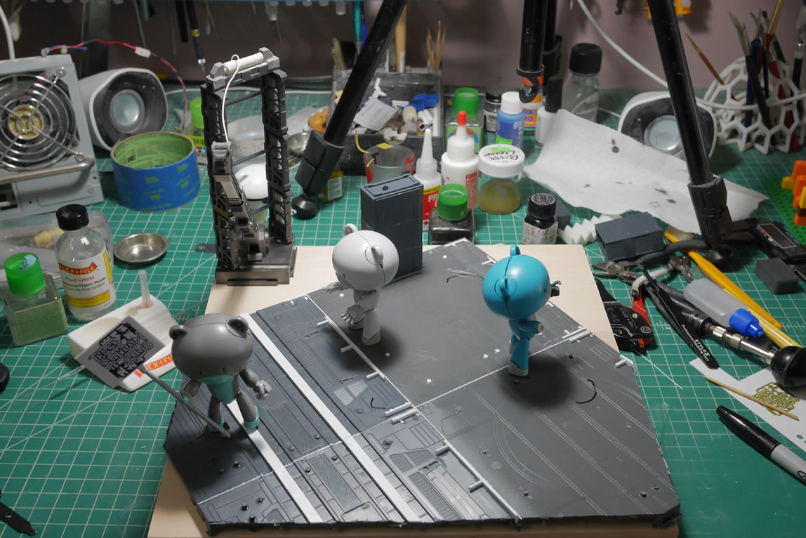
The crane operator needs a control panel. Time to rummage through parts to find something fitting. I found the following, arm piece to the bear guy, the foot of the bear guy, and a part from the kshatriya repair’s fuel tanks I believe. Mashed together, I get a basic control panel feel.
A little sanding here, a little putty there, some drilling in the vent, some cricut cut instrumental panel details and some styrene and other plastic bits glued together form the basic control panel.
The main kit is done and completed pictures are here
July 3, 2018: The kit has been done for a few weeks now, this update just finishes the base I had started when I needed a break from cleaning up and fixing the resin binders. I touched on a few things on the last update with the basics of the base, but other than just slapping things together, I didn’t do any focused work since I felt the best thing was to just power through and finish the monster first.
Returning to this full time since that kit was done, I finished up the detailing for the control panel. I use the cricut to make some button templates and started to glue in some detail bits. More parts from the ball kit to create the lever. I used some styrene tubes and made more magnet wire wrapped cables that I glued into position. And this part is ready for primer.
I originally measured out and cut the base plastic bits on a 12×12 raised wood box. That gave it a lot of unnecessary height since the damn BG kit was fairly tall, so I needed to find a different solution. I picked up a thin plywood board 12×12 board that worked perfectly with what I started. The plastic part of the base is getting filled and sanding work is in high gear to clean up the holes on the board. These bases are nice, and I understand the need for the holes to stick things in that whole world of snap fit. But as a model builder, these holes just take away from the effect if they’re used in a diorama. I used left over spruce bits to glue into place and styrene bits to fill in the more rectangular holes.
The bear guys are taken apart and the seams glued as well as the holes in the back of them filled with more left over plastic sprue.
These holes work to fit the little guys onto chairs or other snap fit things. Being standalone, these holes make no sense, so they are filled. Sprue bits and glue. The next picture is the hands that I used for most of the petits. It is just a modified version of the builder’s parts. I removed the end digits to make the hands stubby, so here’s a comparison with the original hands. Thanks again to reddit for that suggestion.
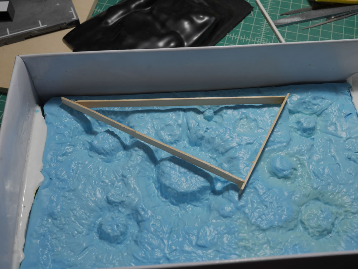
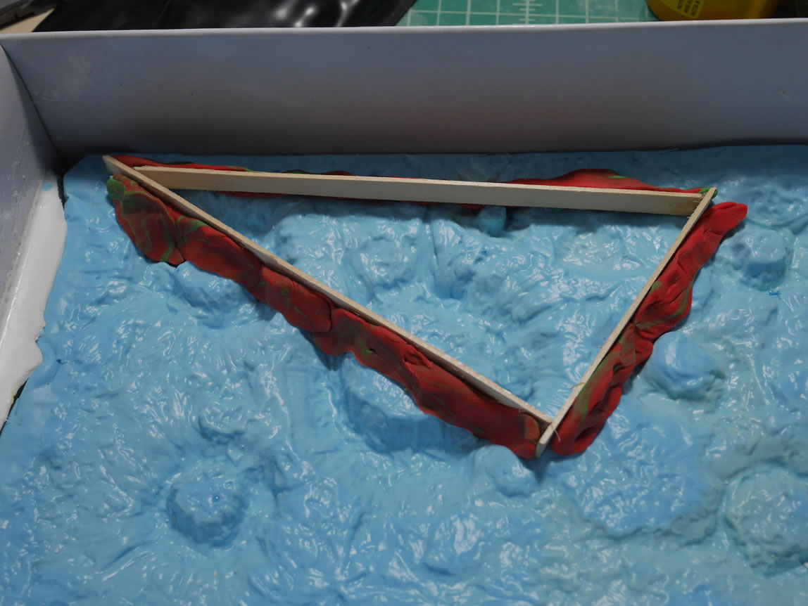
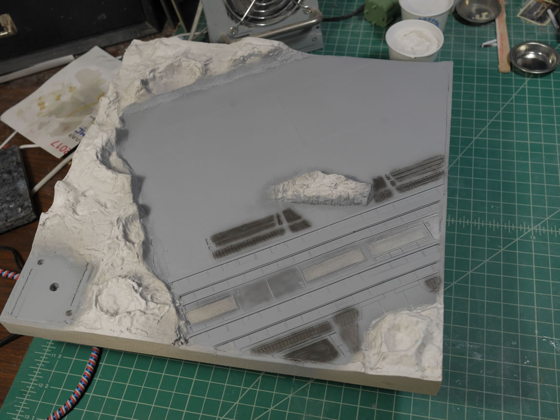
The plastic base is glued to the wood board so I can start working on filling the negative areas with plaster craters and rocks. In a short sighted moment of brilliance, I made a wood frame measured out so I can make a mold. This all makes sense to me until I demold the damn thing. But that comes later. The frame is laid against a silicone mold I made years ago of a plastic crater sheet. Playdough is lined along the bottom edges to keep the frame in place and keep the plaster from flowing out under the frame.
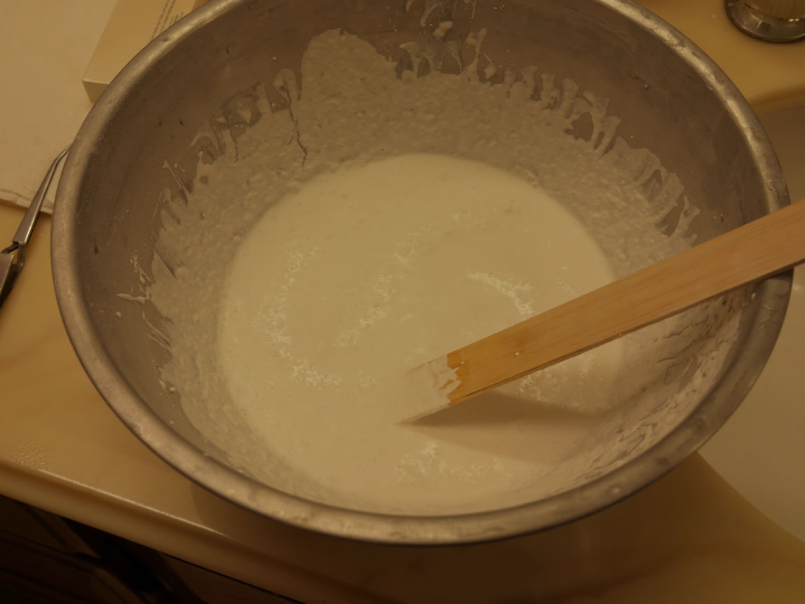
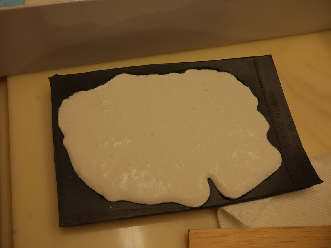
The plaster I use is called hydrocal and mixes with water which then hardens rather quickly and depending on relative temperature and humidity, will cure in a day or two. So from the pictures, when I flipped over the framed plastic piece, it doesn’t fit because I should have made a mirror image of the space I was trying to fill. I’m using the bottom of the mold not the top. Fail all around. Almost.
This post will jump around because it’s just how I worked these last week and a half. The crane frame was build hastily so there are some much needed attention to fixing or just hiding some of the bad things about these parts. I used the cricut to design and cut out perfectly sized groove styrene to help hide the holes where I bridged the two parts to form the main frame. The insides get some detail parts to cover these unsightly holes.
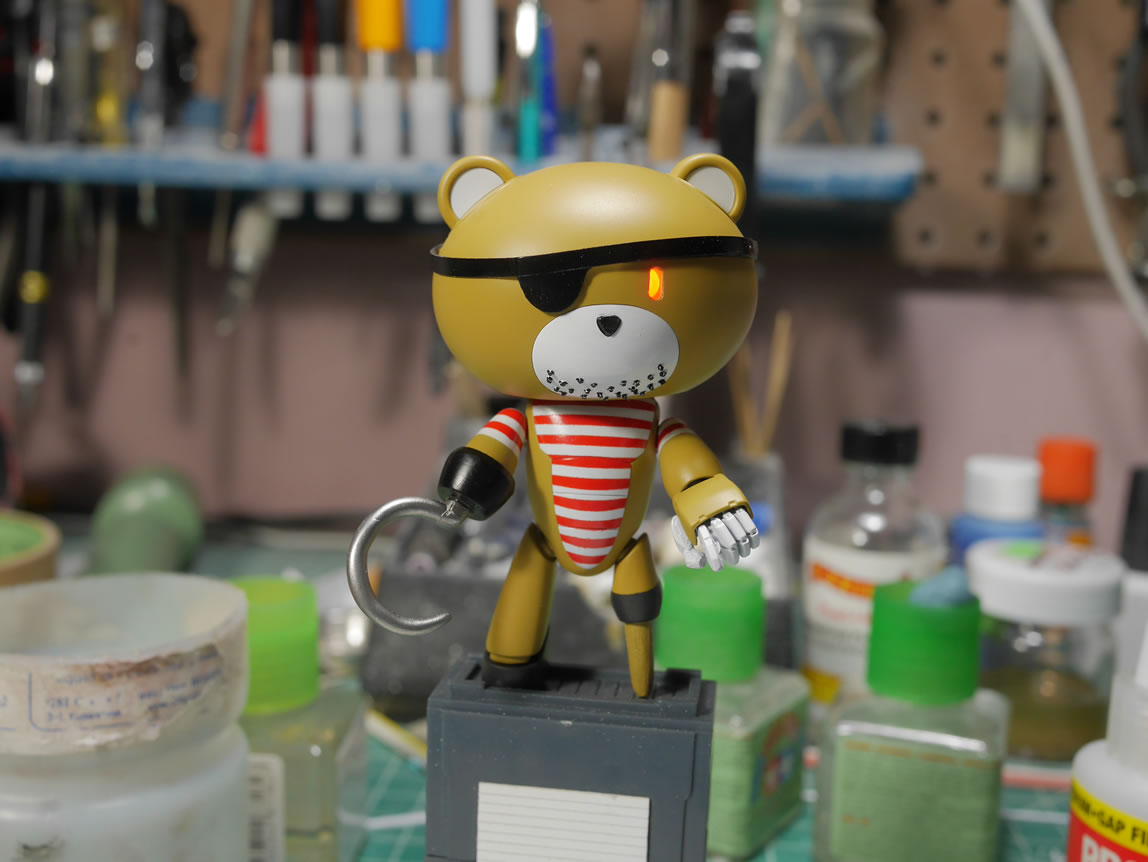
Back to the pirate petit. To add to the pirate theme, I wanted to give him some stubble. I didn’t want to just paint in stubble, I wanted a little dimension to it, so I marked off the face and glued in plastic bits to create the stubble.
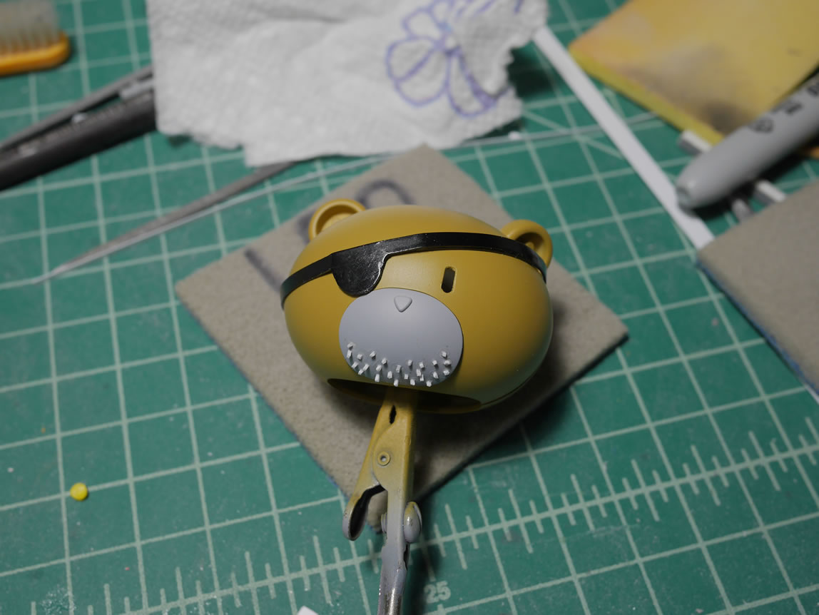
The chest of the pirate is masked off and painted in red and white. The face piece is painted and stubble highlighted, everything goes back together and I have a more pirate, pirate petit.
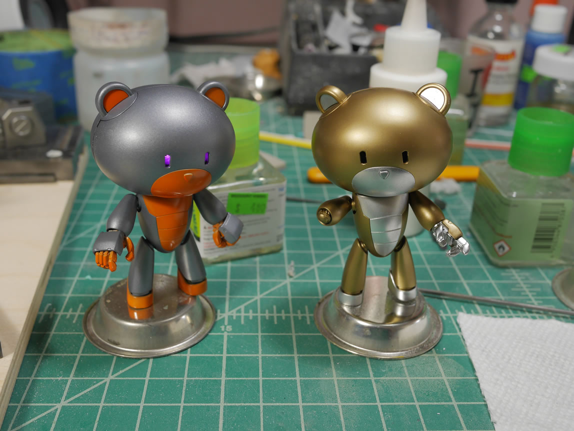
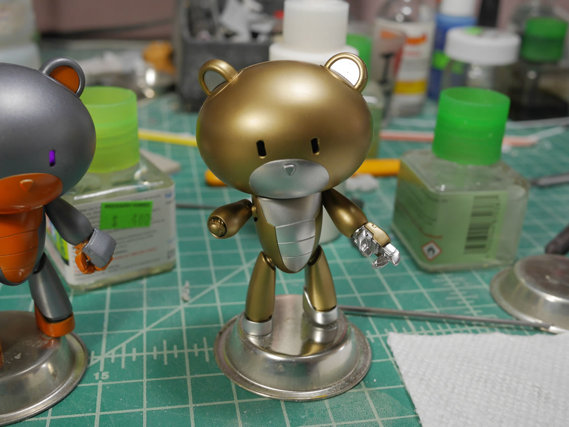
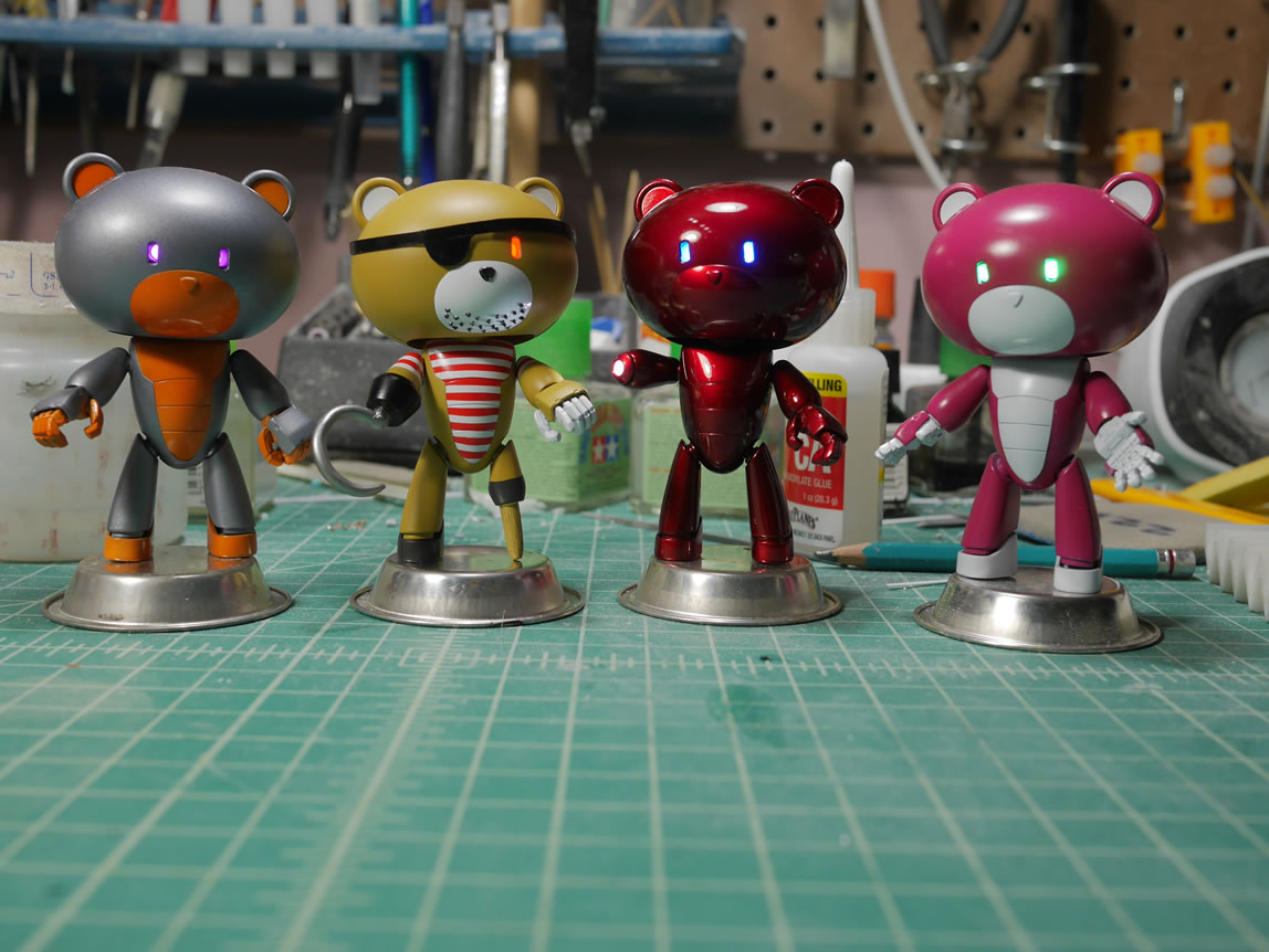
The other petits are not ignored. Each has their own color scheme. The real “pilot” is painted in the same colors as the main suit and hence the motorcycle helmet is meant for him. The inspector petit is painted in alclad polished brass and aluminum. Clear red is painted over that guy to get a candy red with darker tones on the main body and lighter tones on the highlights. It didn’t really work out too well since I had all the parts together when I sprayed the clear. In hindsight, I should have separate the parts out and had better control to do a lighter tone over the aluminum parts. But the petit crew is done, almost. I still need some detail painting and the clears and maybe some deckals.
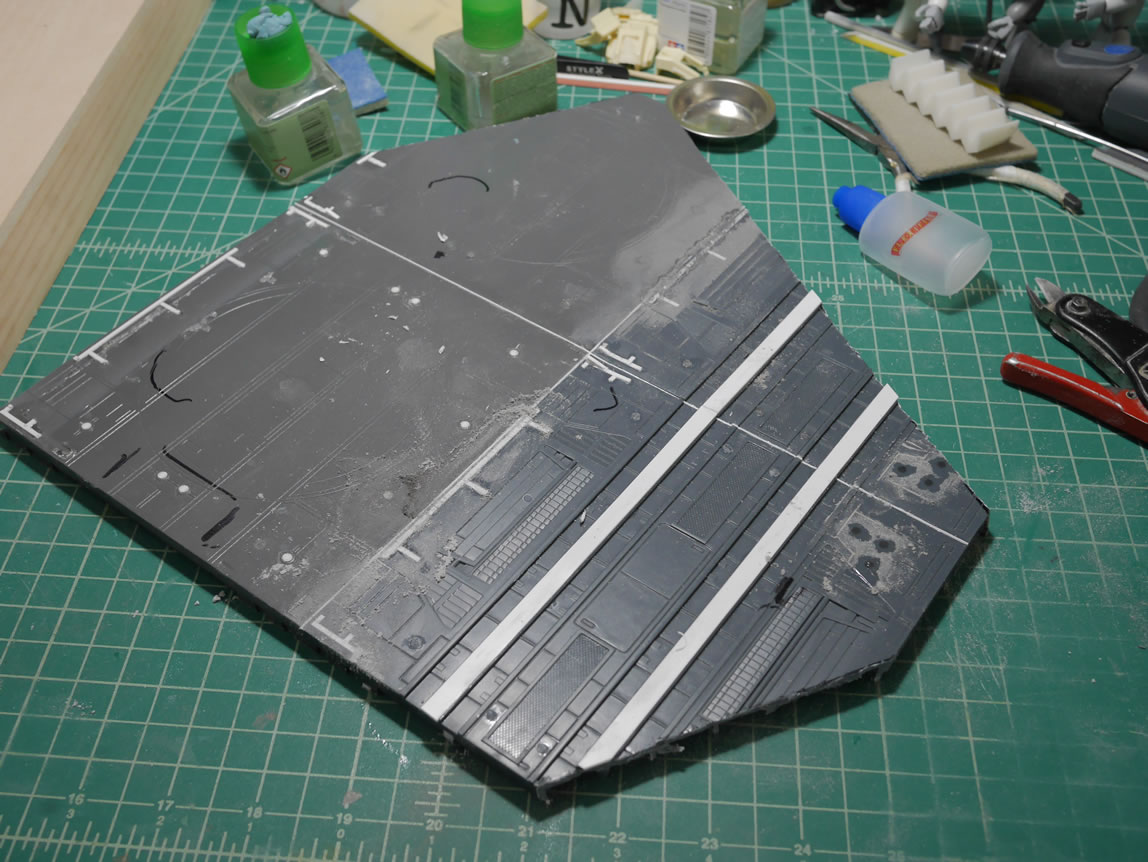
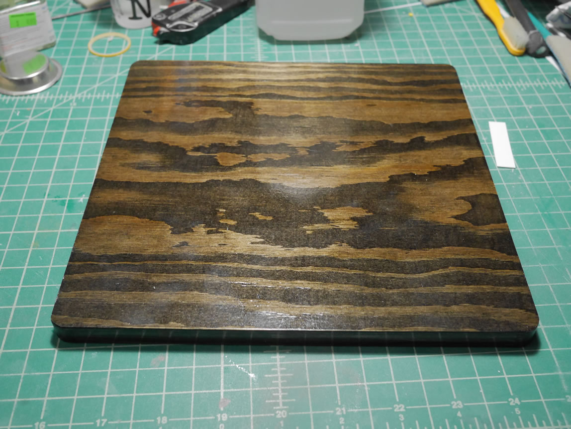
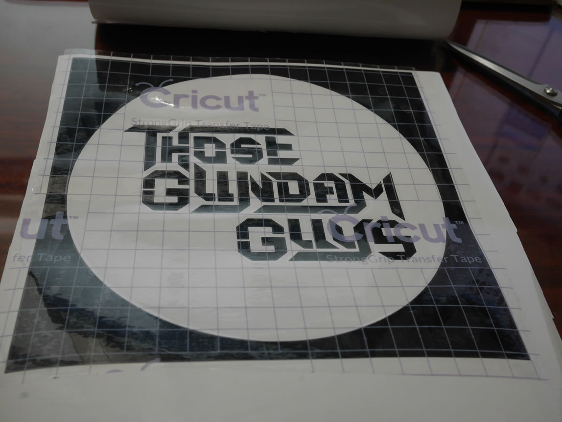
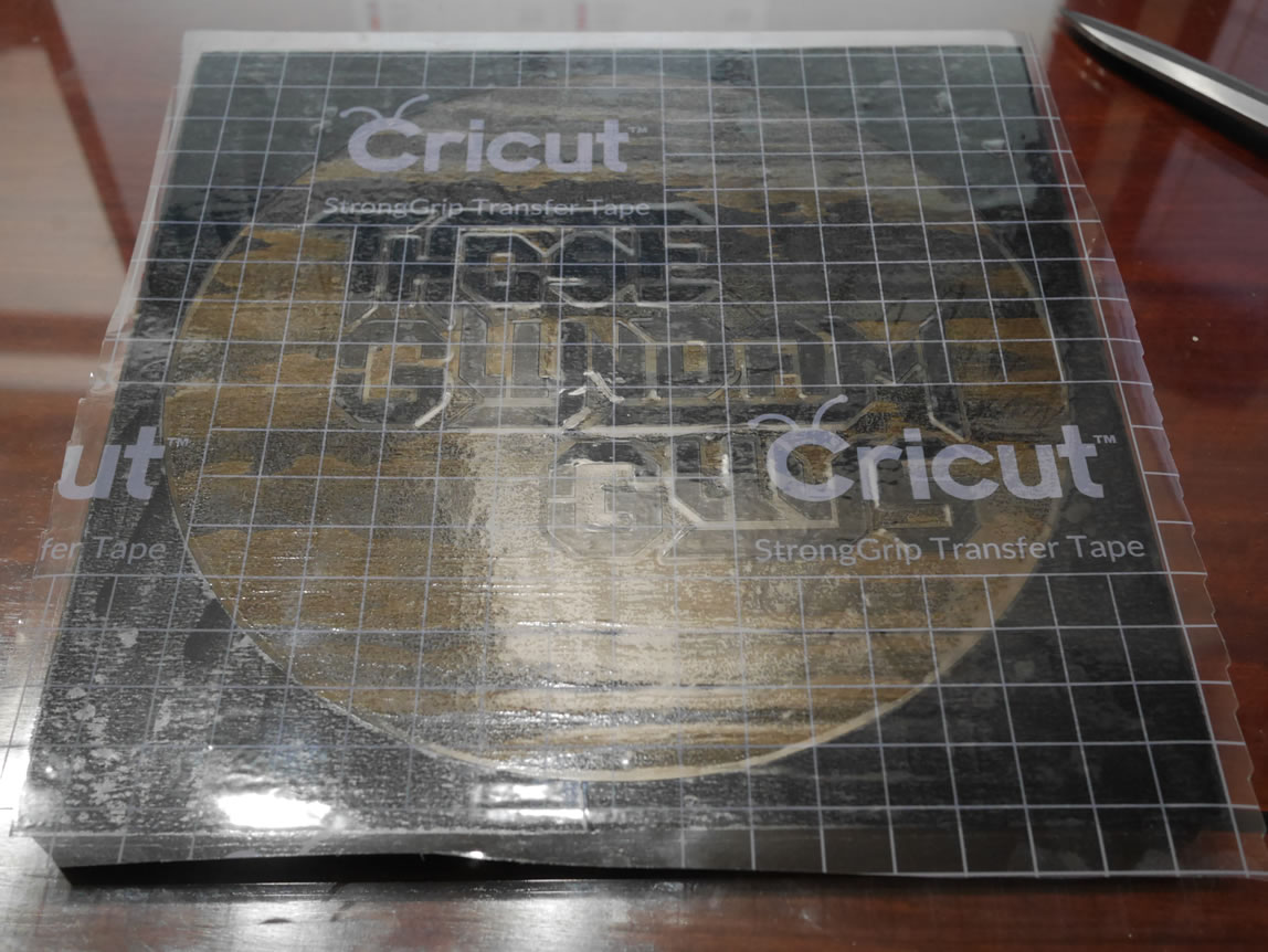
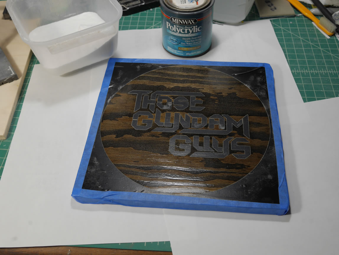
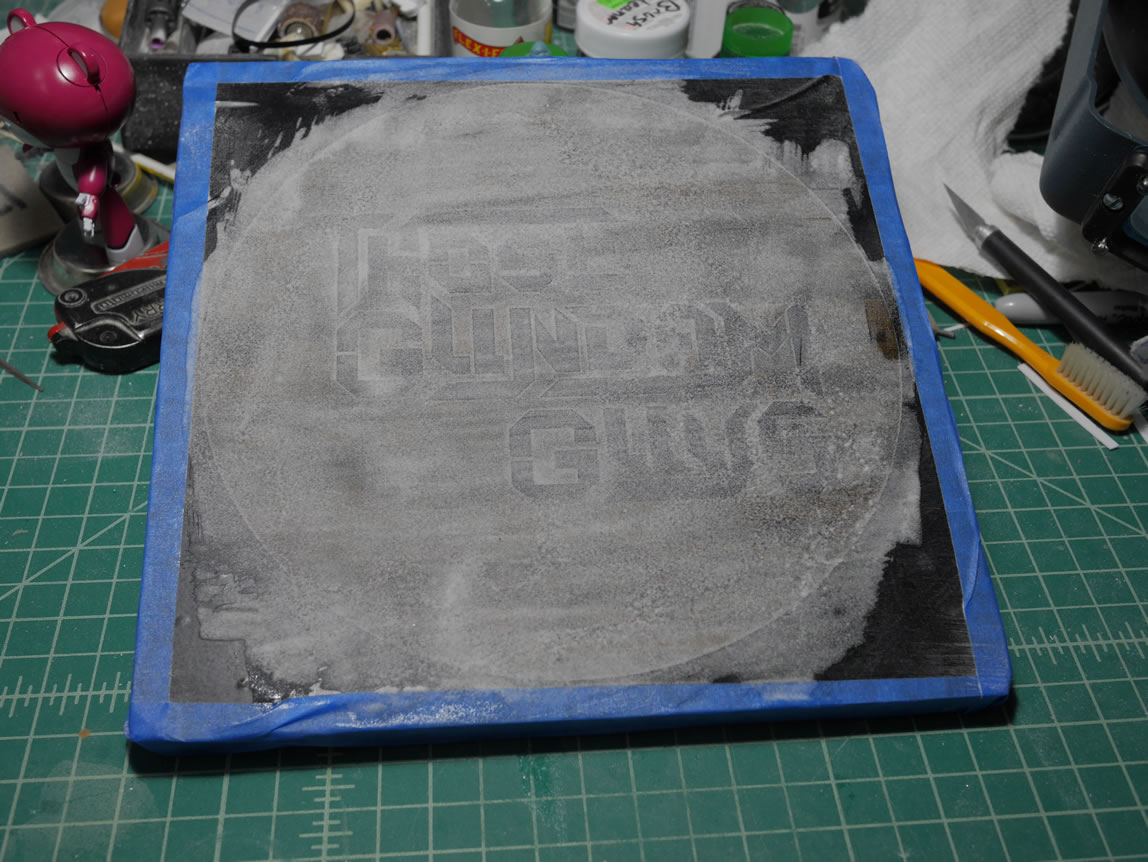
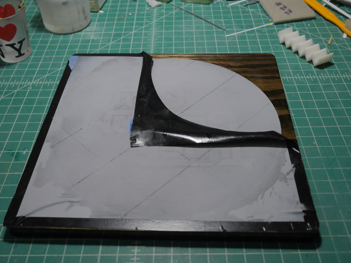
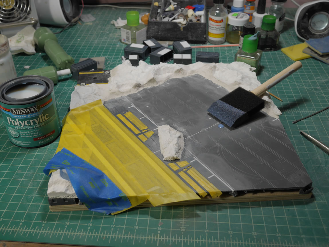
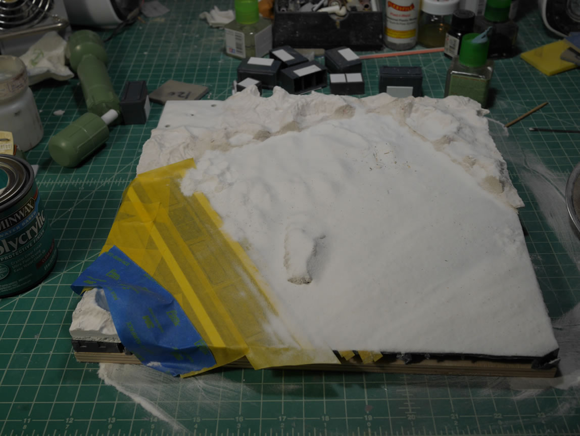
I was trying to finish the project for AX, but I also know that life throws shit at the most unexpected moments. So I spent some time to prepare a simpler back up display base. I started with a wood base that I also picked up when I got the new lower profile plywood base. This was stained and clear glossed days ago. I was going to mask off a square and do up a quick little tarmac on top but the idea to tweak that popped into my head. Going back to the cricut machine, I designed a mask using vinyl tape. I created a circle and inside, I added our TGG logo. The vinyl is cut and I removed the excess from the main sheet. Over this, I used cricut vinyl transfer tape and transferred the designed to the wood base. Excess on the sides are masked off with blue painters tape.
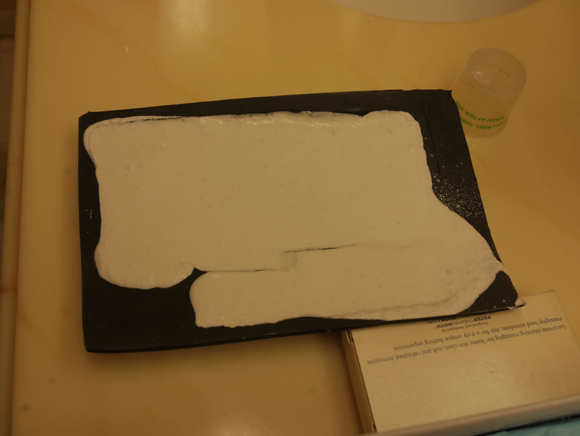
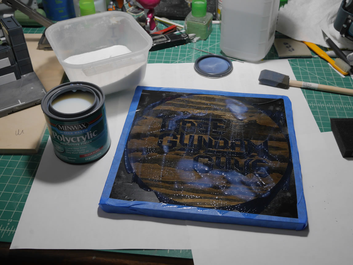
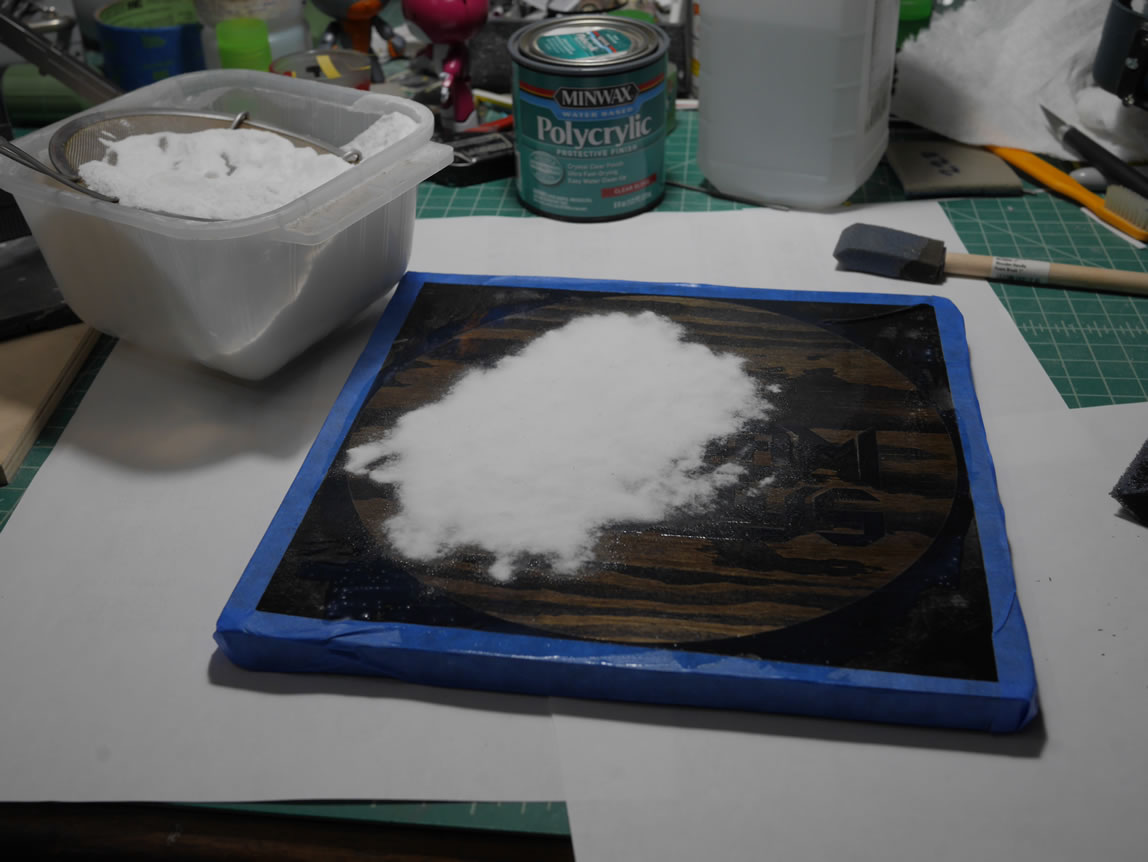
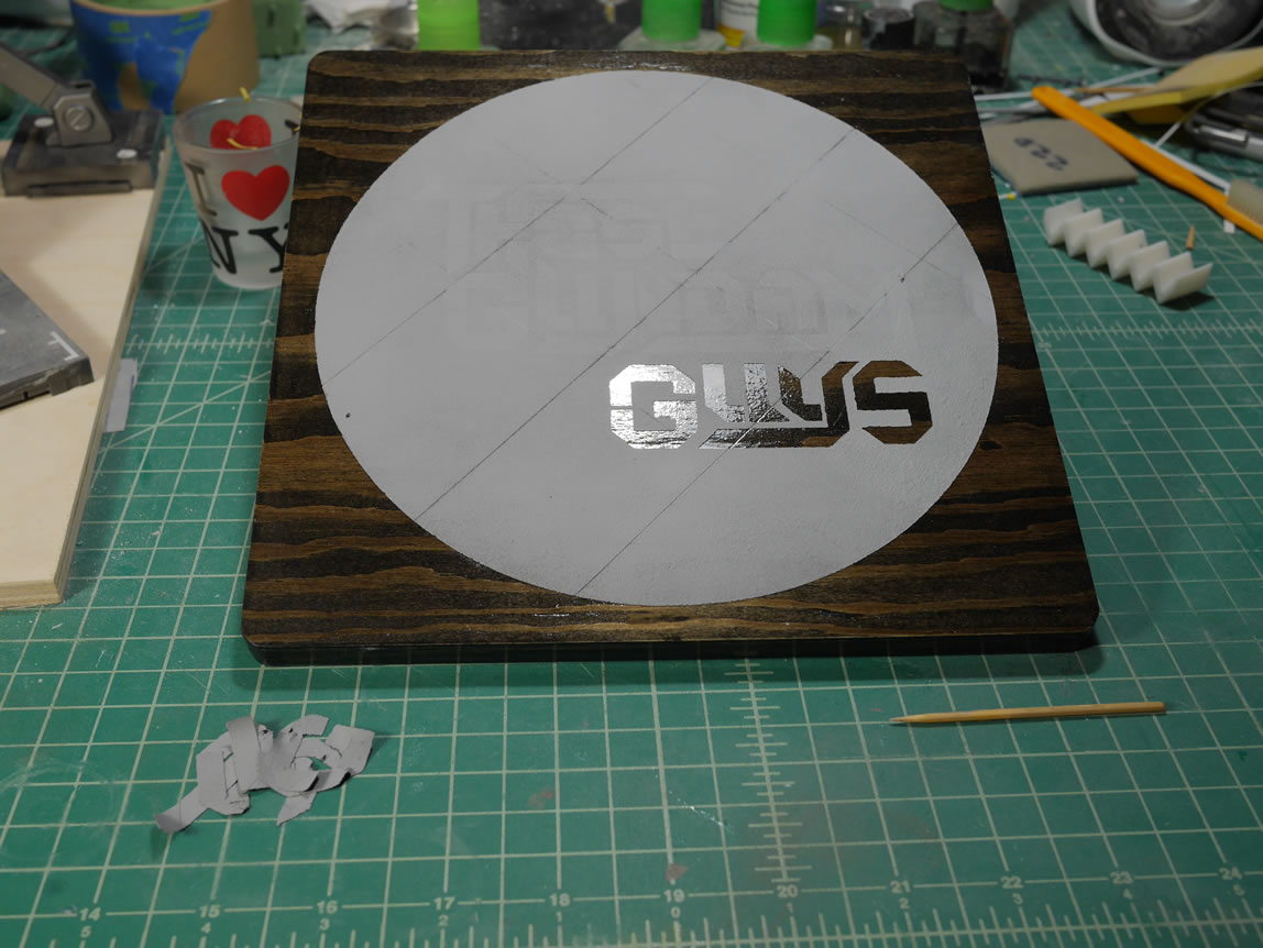
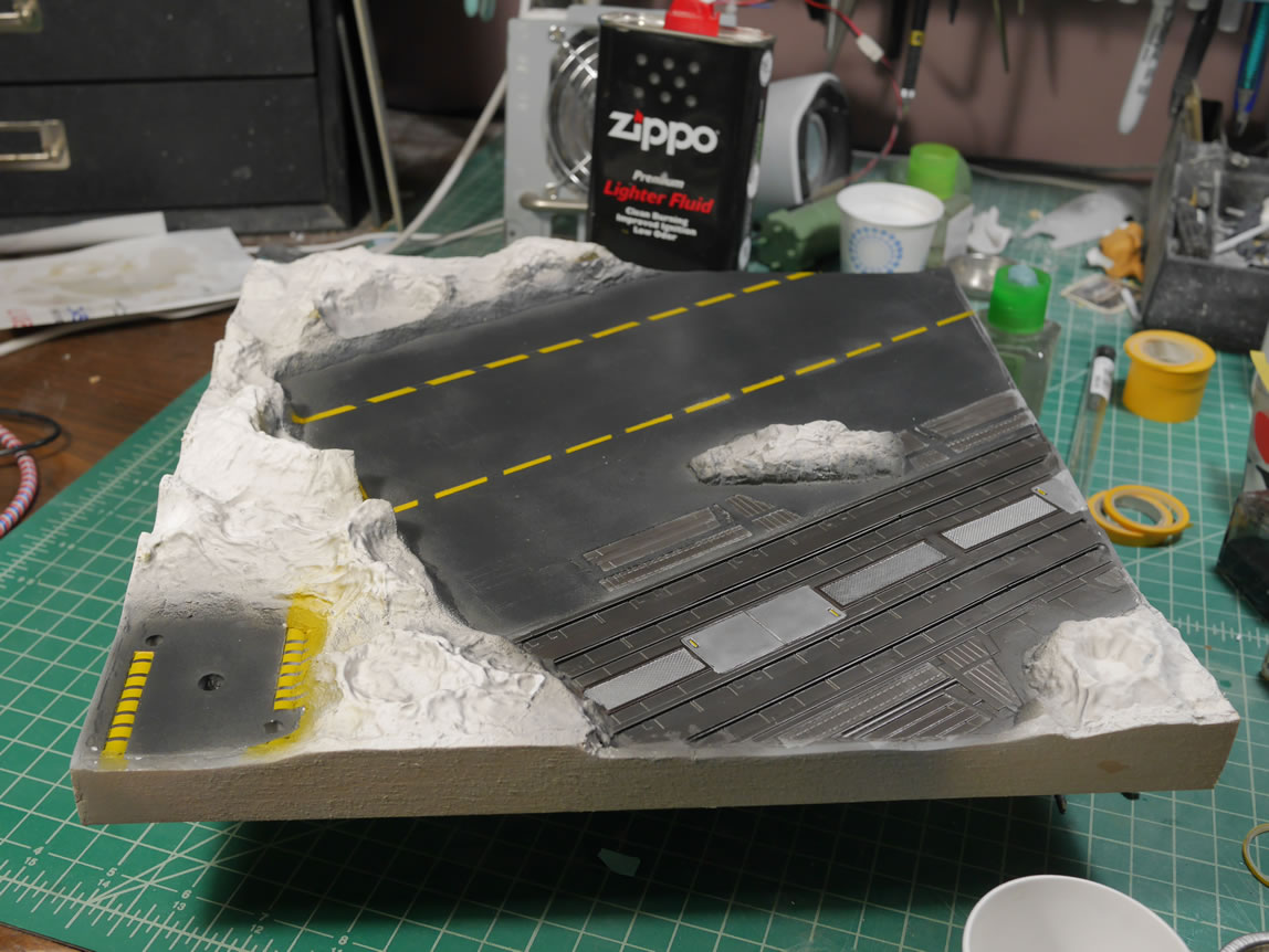
The next steps are just the creation of the tarmac. An acrylic medium is spread over the exposed wood areas. Baking soda is shifted over the base and then I have a whole lot of cocaine. Once that dries, I brushed off the excess back into the box of soda. A quick sand helps even some of the rough edges.
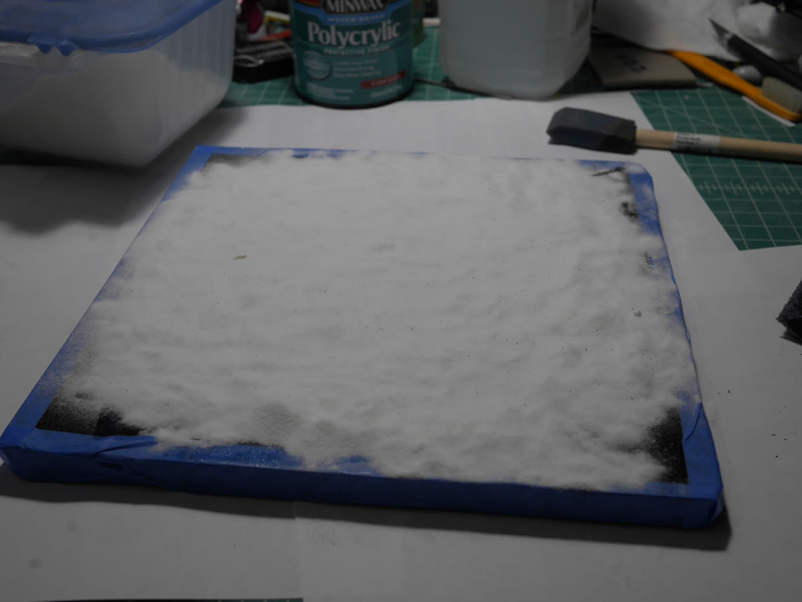
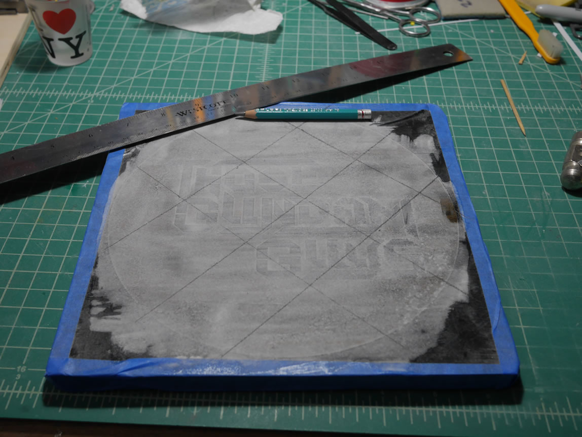
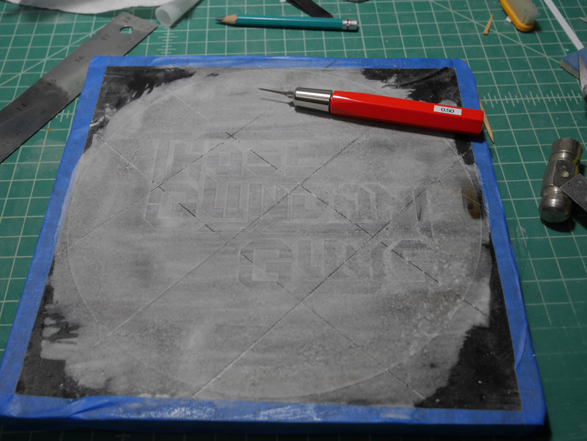
The ruler and scriber come out to cut in some grooves into the surface to accent the tarmac feel. Once scribed, the base is sprayed with primer. Once the primer dries, the mask is carefully removed.
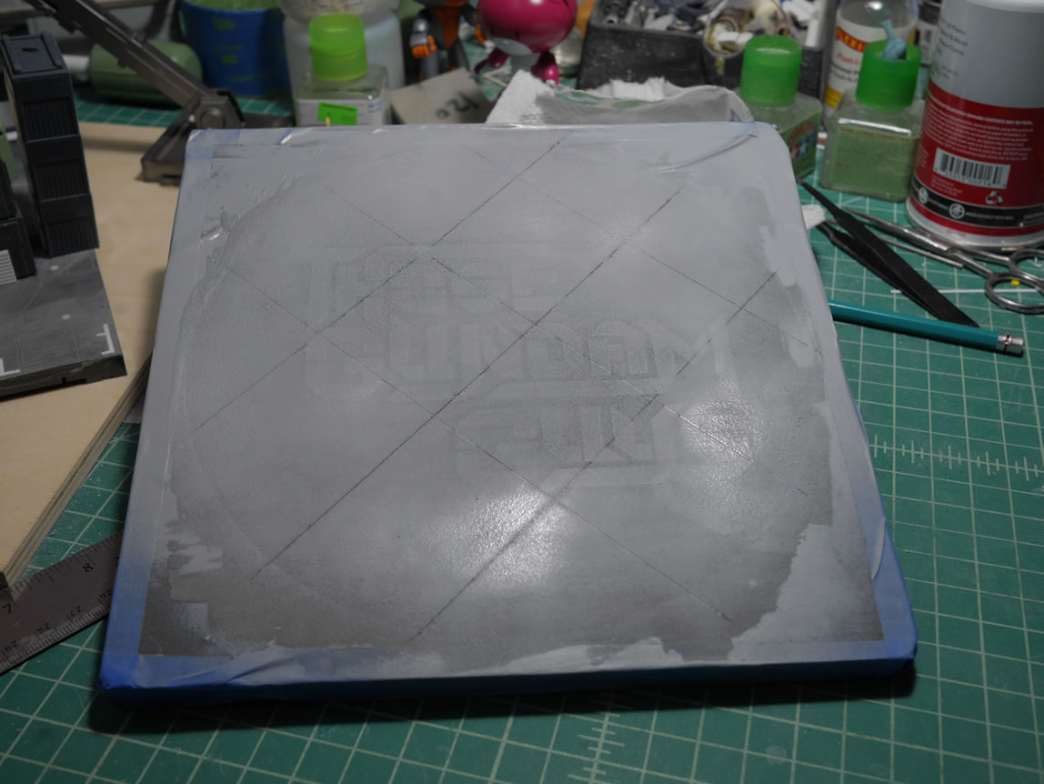
Vinyl sticks better than masking tape, so some care in removal are needed lift up the mask. But once done, I have my backup display base. That I apparently forgot to take a completed picture.
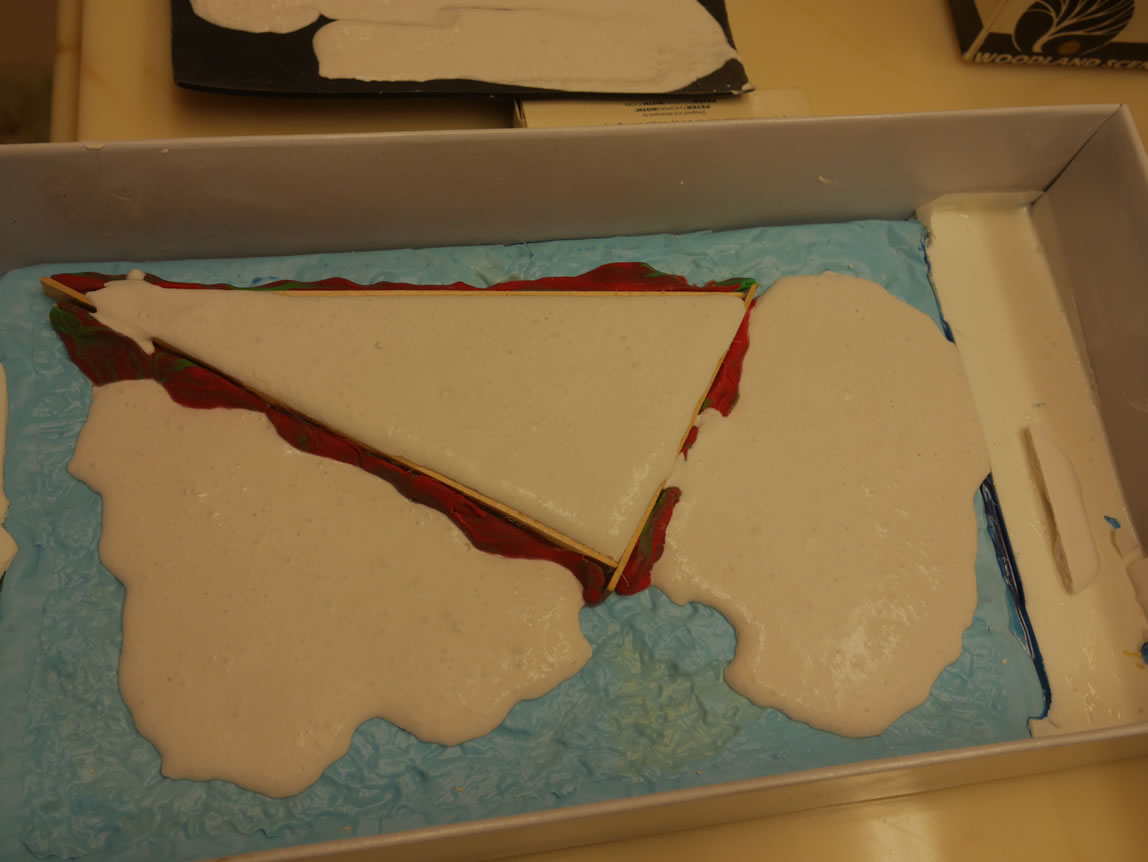
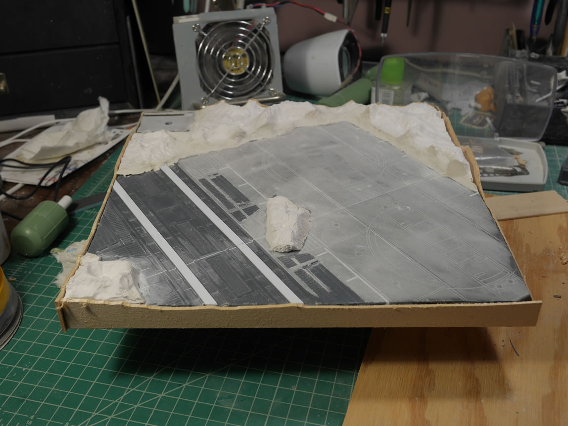
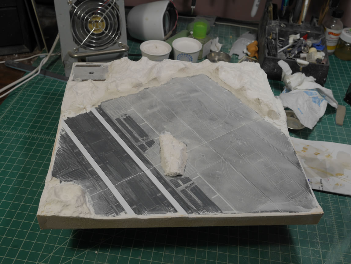
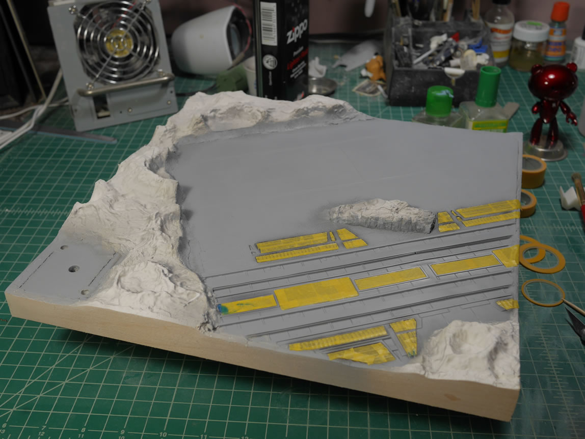
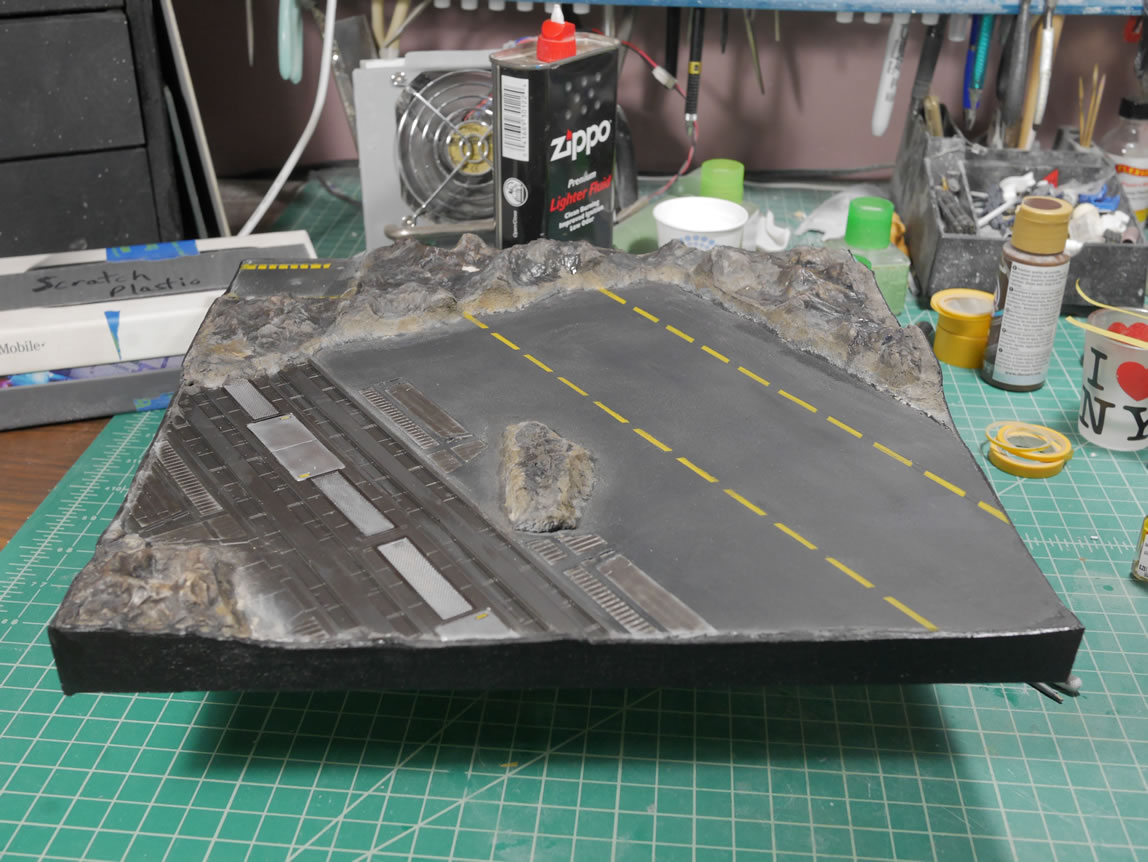
All the while, I’m still working on the main display base. The plaster pieces have dried and I can start assembling them on the base to see where things fit. The pieces are not an exact fit, but I can use paper clay or even more plaster to transition between different pieces and onto the board itself. The plaster is glued to the surface and paper clay is used to fill in any gapes between the plaster as well as between the plaster and the board. I apply the tarmac technique to the base and mask off areas that do not get the effect.
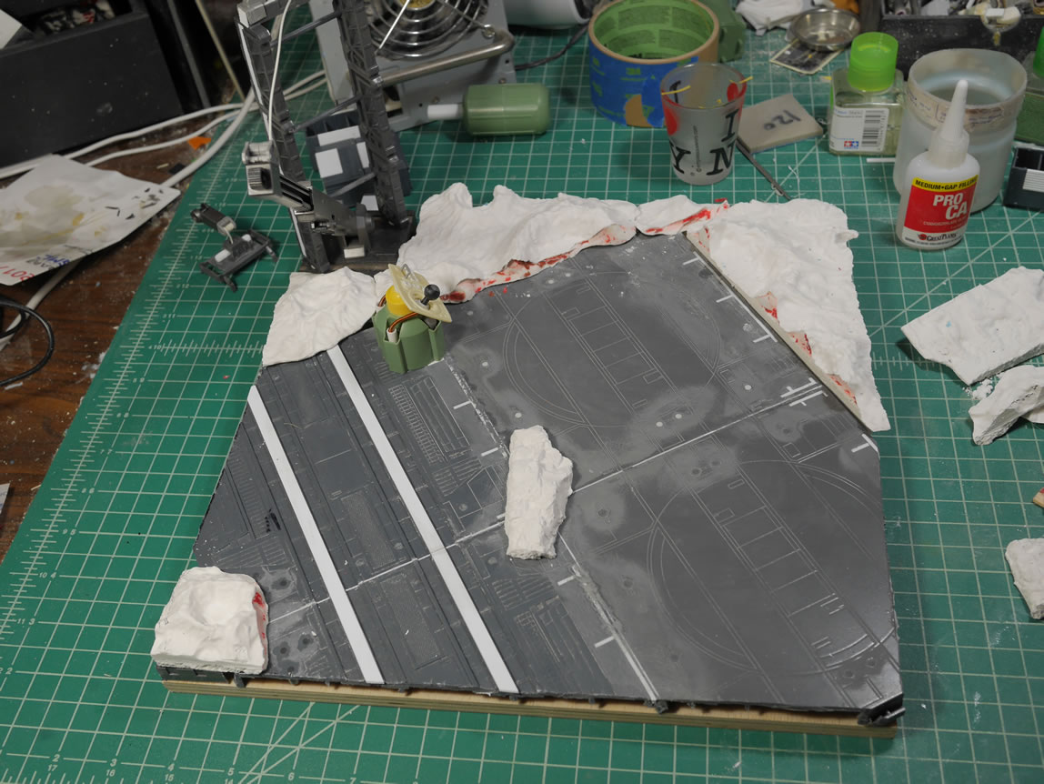
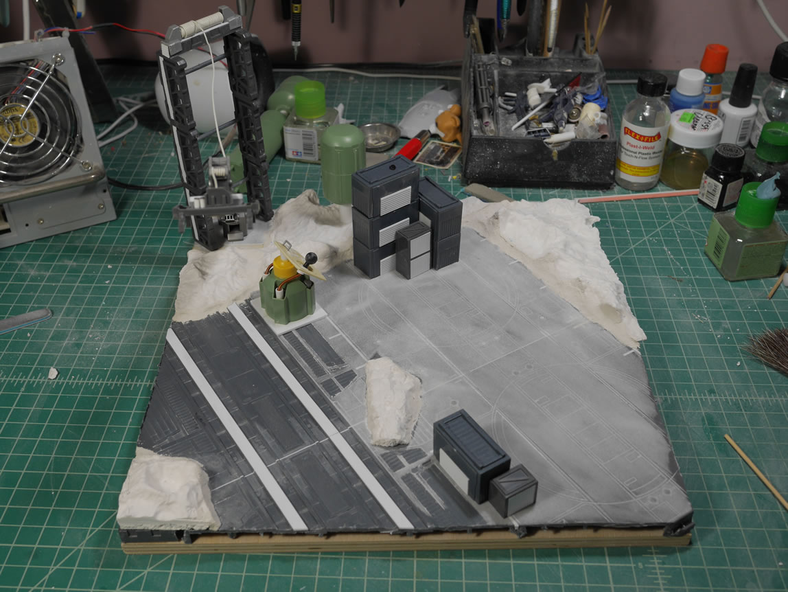
The tarmac is partially done so time for another test fitting with all the principal players to see how everything fits. I need photos so that while I continue to work, I don’t forget where I position the pieces. This are starting to take form. I may finish this in time.

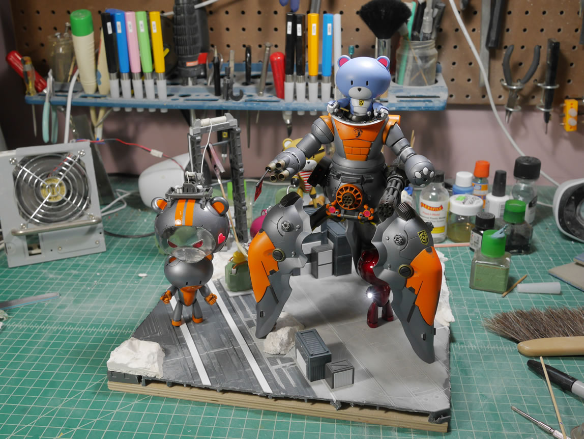
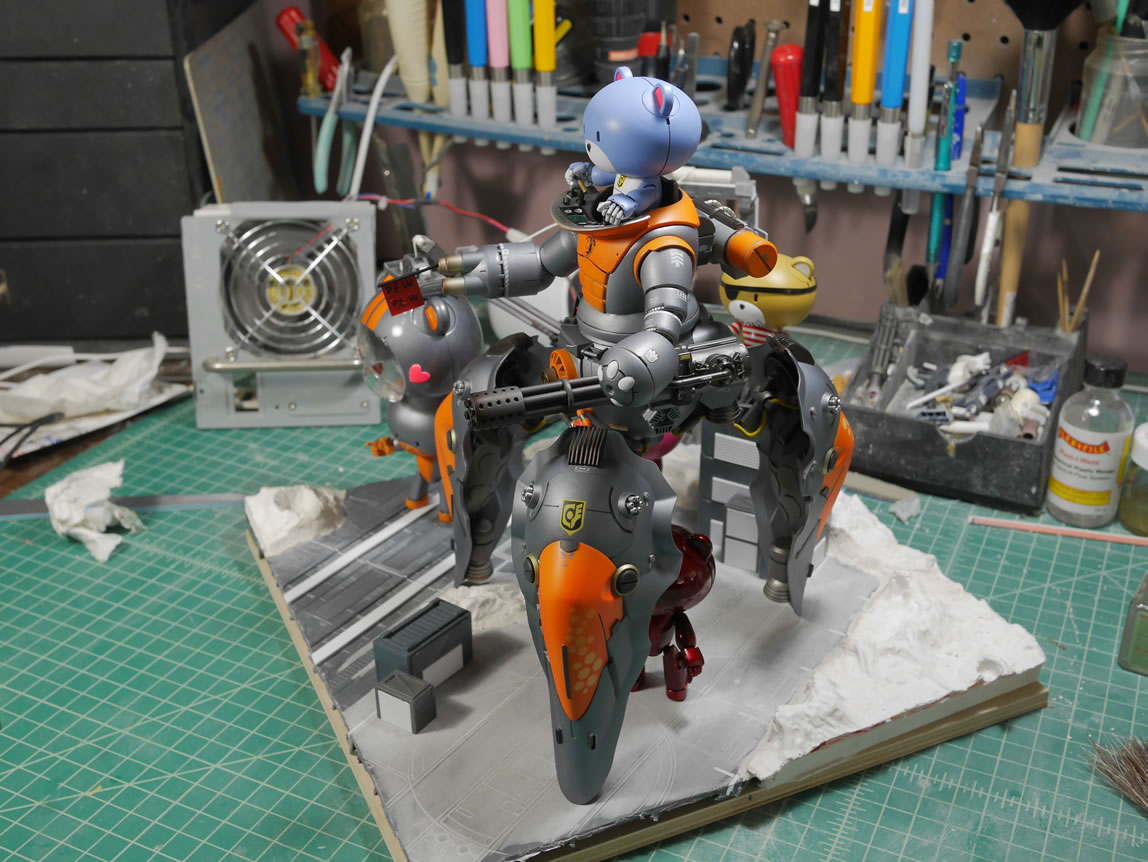
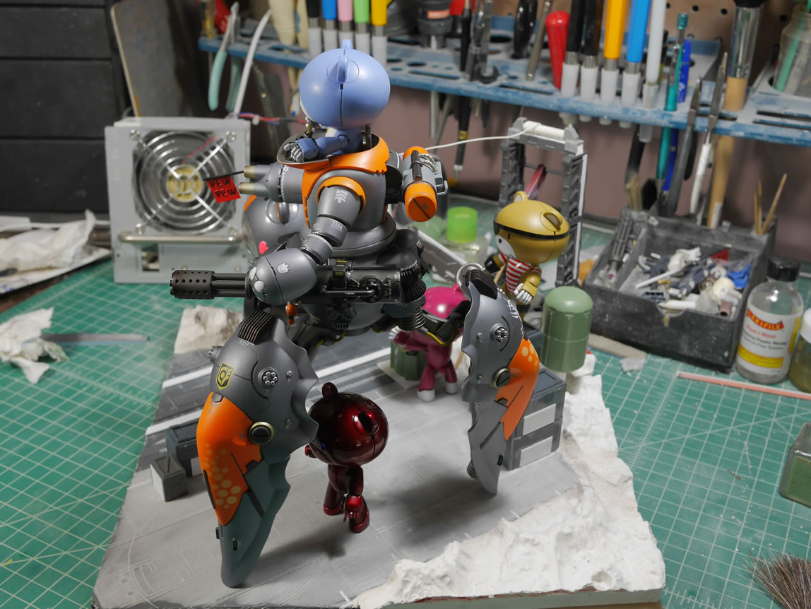
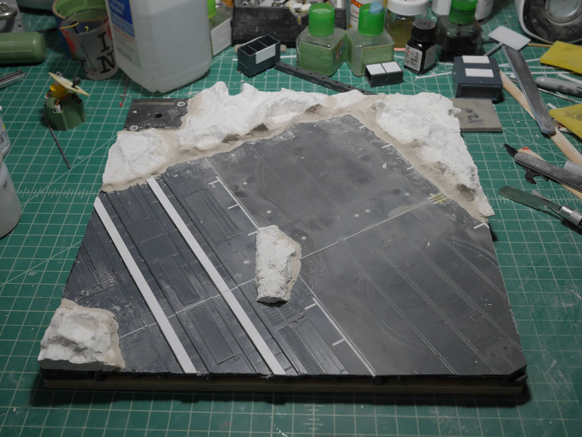
Here’s the reference picture without the petits or the main kit. Again, this is so that I know where to continue my build.
The first picture is the base with a balsa wood border glued into position. This helps hide all the ugliness of the raised platform ad just give a nice border to the diorama. The edges of the wood and the base have gaps that need filling. I mixed up some plaster and just filled the gaps with the plaster. Wood filler is used to fill in any gaps on the wood side of things. In the second picture, the lower left corner has wood filler. The edges are sanded and touch ups are done. The final picture is just the flat areas on the base primed.
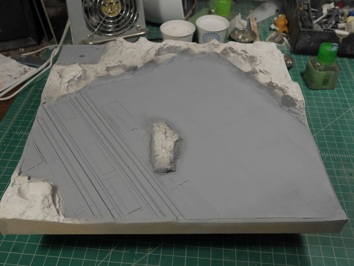
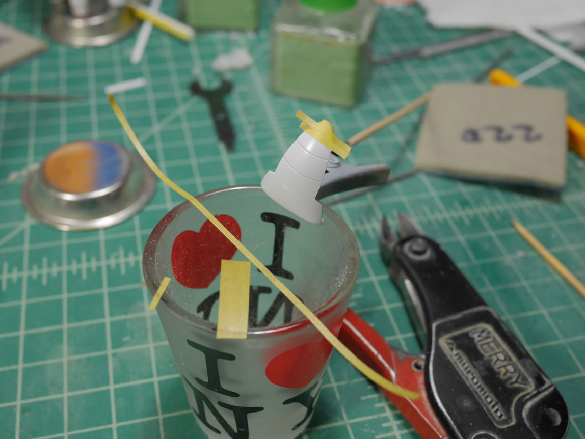
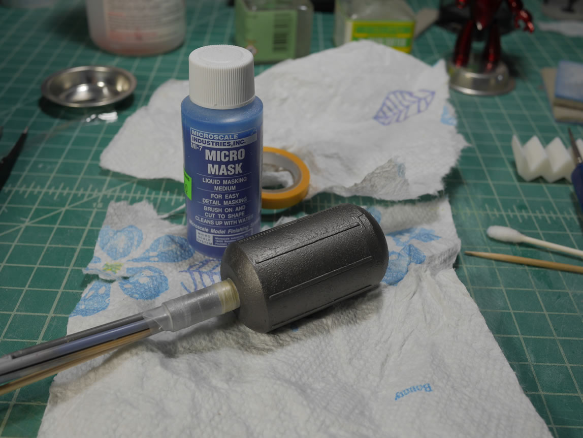
Speaking of primer, time to prime the rest of the detail bits; shipping containers, crane, control panel and water tower. I used the glue + tooth brush cast iron surface technique to create the texture on the water tower. After priming, a layer of alclad steel is painted. Once that is all cured, I applied some liquid mask so I can create a weathered paint chipped look to the part.
Metallics are painted on the base and then masked off so that I can paint in the main color for the tarmac. I used german grey for the tarmac areas.
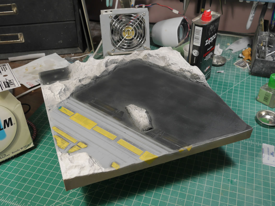
More mask and paint and mask and paint to get details and the rest of the base painted.
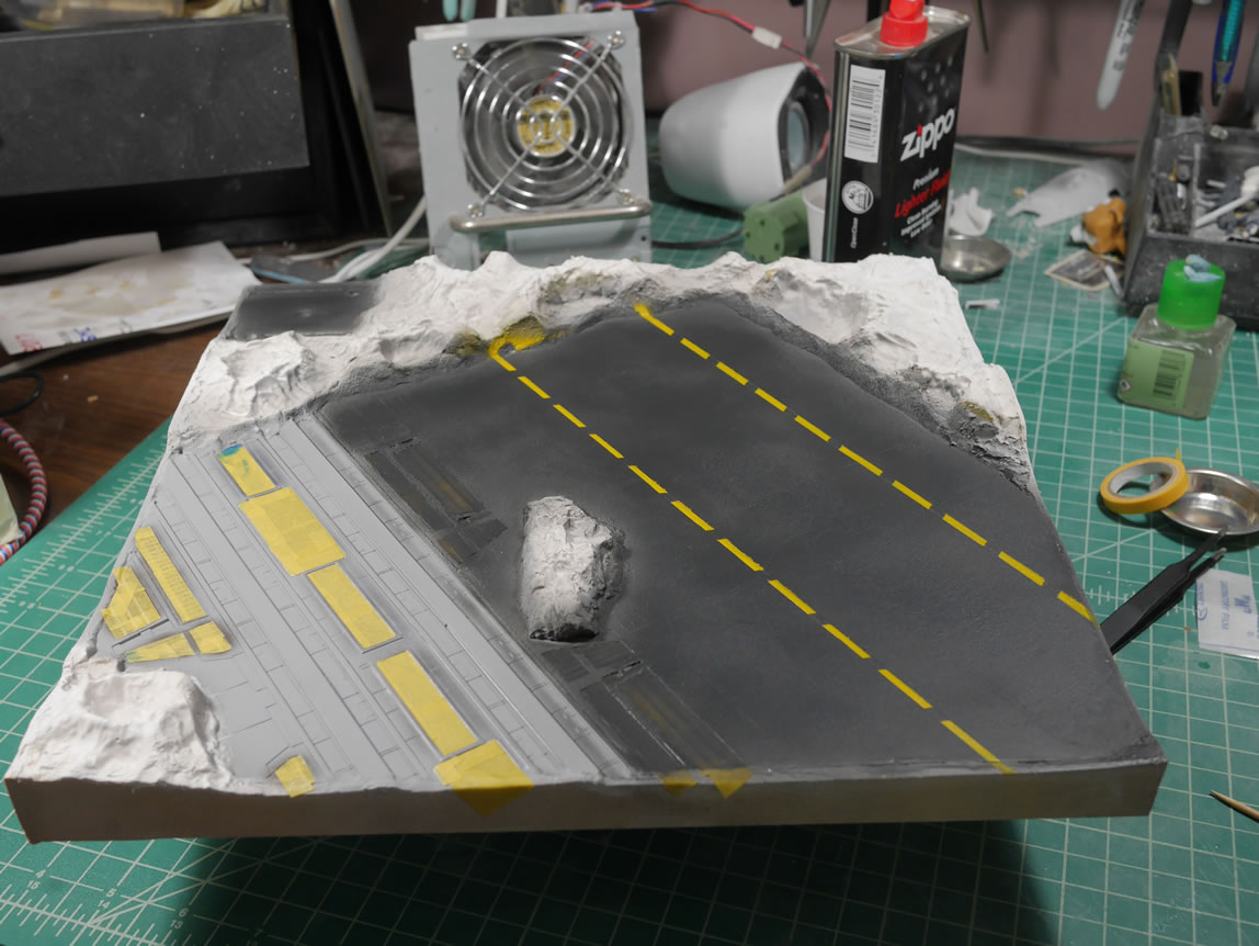
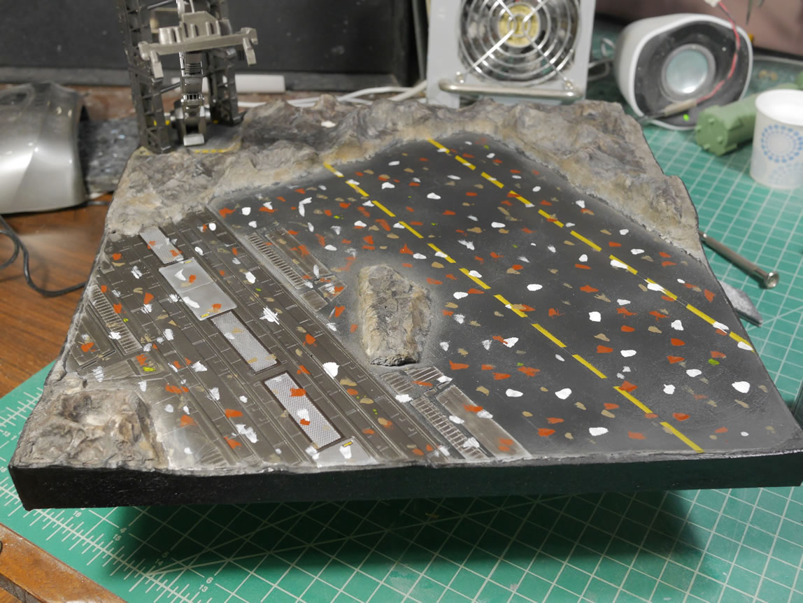
A series of washes paint up the craters to complete the base scene. But the surface looks too clean.
The last bit of work was to apply a filter to the surface as well as to the shipping containers. They were decaled and clear coated to protect the plastic as well as the decals. Dots of enamel white, rust, dark earth, and yellow are applied to these surfaces. They are then wiped away with a rough brush loaded with enamel thinner (lighter fluid) which weathered the surface nicely.
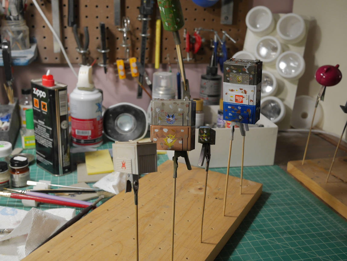
The project is still not done at the time of this posting. I’m still waiting for the clear light sheen clear coat to cure on the petits and control panel. The containers and crane are glued to the base and are still curing from the enamel filters. Later tonight I will spray a clear flat for those pieces and add some pastel weathering to finish things up. For those going to AX2018, see you all there, and you can check out the kit at the GBWC competition.