January 15, 2014:
I’ve finally gotten off my ass and away from that bloody Gundam Battle Operation. Been stuck in a vortex of that game for a while and finally quelling the addiction with something else just as addictive, but much more productive as I actually have a tangible end result. And it has been a while since I posted anything. Again, blaming the GBO addition. But on to the purpose of this post, that new Ver. Ka Sazabi. The original design for this suit was penned by Yukata Izubuchi, the same guy also designed the Dogas, Nu, Hygogg, etc. Most of my favorite mecha designs were originally done by him. I favor a more simplistic design in comparison to most of Katoki’s style; but I do appreciate the application of Katoki themes to the original Izubuchi designs. There are several resin variants for the Nu and Saz that just go way beyond anything I enjoy with levels of panel lines, greeblies, tubes and wiring. I can appreciate it, but my personal taste leans towards a more simplicity. There’s a balance between the two extremes and I fall somewhere slightly short of the middle – so, I’m not a complete fence sitter.
I’ve built the original MG Saz, a kit that even Izubuchi didn’t admit to liking very much. I’ve rebuilt that same kit twice over, the final version a Core-Works conversion. That said, I’m fairly familiar with the kit’s design. So I picked up this kit from the local distributor a couple of days prior to the official release. Friends with benefits I guess. I’m never in a rush, but the novelty of having this before the majority of the world was kinda cool, granted I wasn’t allowed to post up pictures – but as part of the TGG gang, we actually got real hands on look at the entire kit a full week before it’s release at our monthly build gathering. So the novelty of actually snapping pictures of my own kit when I got it was gone.
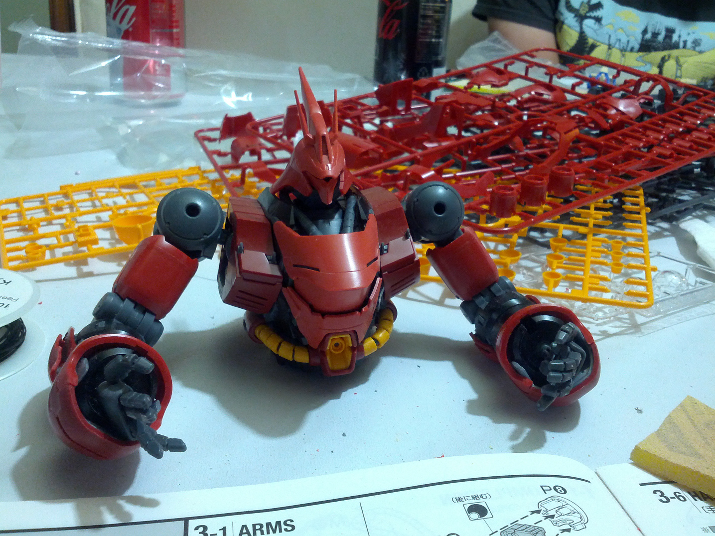
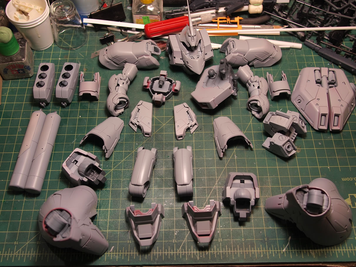
This past weekend was the first build gathering of the year. I started with finishing up the basic build and sanding of the resin Kampfer I had been working on last build gathering, and with all the parks soaking in purple power, I had nothing else on my plate. Angel had already started on his Ka Saz, so I grabbed the gigantic box out of my workshop and started on page one, clipping, sanding, and snapping the sucker together.
There’s a bit of departure from the original design, implementing the ideals of a “psycho-frame”, fall out from the Unicorn design and last year’s Nu. I didn’t care for it on the Nu, but certain elements on the Saz appealed to me. Most of the shifting will be glued down, but there will be a few areas where I’ll glue down the “opened” option – namely the back of the forearm areas that expose newly added verniers. At the end of the gathering, I got about as far as the upper torso sans shoulders.
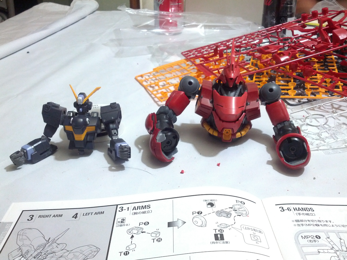
Here’s a size comparison shot with the Xbones 2 that Mike was working on at the gathering. Fun juxtaposition of probably one of the smallest 1/100 scale MGs against one of the larger.
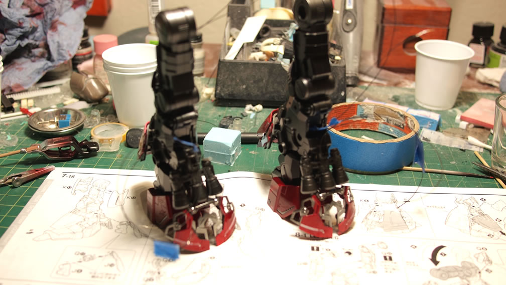
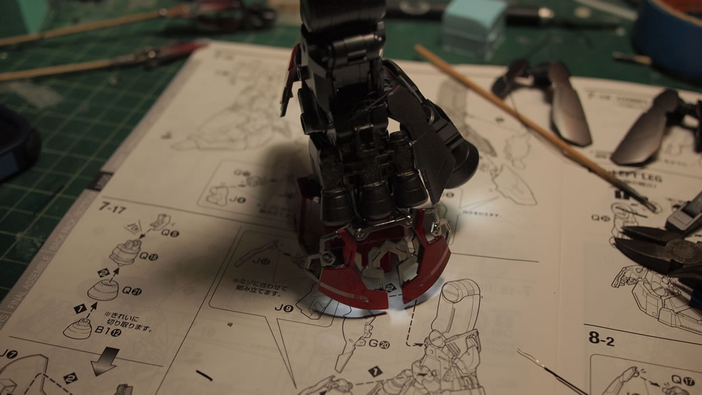
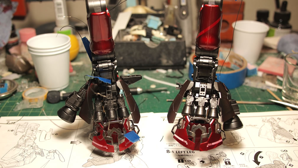
The following day, I started sometime after getting up and sitting myself in front of the TV with the NFL divisional playoffs on, followed by several different movies, I got about as far as step 8-2 which got me close to completing the left leg. A quick look at the clock showed it was a bit past midnight encroaching closer to 1 than away from actual midnight, so I had to call it. The damn kit is quite partsy, and I’m being a little more focused in getting all the nubs sanded down, as well as some of the surface imperfections.
Yesterday evening, after work, I brought the kit back into the workshop. Working without visual distractions seem to be best as I’m more focused and work much faster. I do however turn on the radio so that I have music. That seems to be the best environment. The wife comes in and hangs out with me for a while and it’s nice. Now if I can sucker her into working on her own creative projects (Legos, a BearGuy San kit I picked up for her, and god forbid her cross-stitching hobby); the workshop will be nice and warm with all the dogs hanging out instead of just Hugo guarding the room from various imagined intruders.
A break for dinner and catching a couple of episodes of Family Guy on TBS that I’ve never seen, saw me back to work at 10 PM. Again, I only finish the backpack just before the midnight bell tolls. Sanding the damn funnel pieces consumed a decent amount of time.
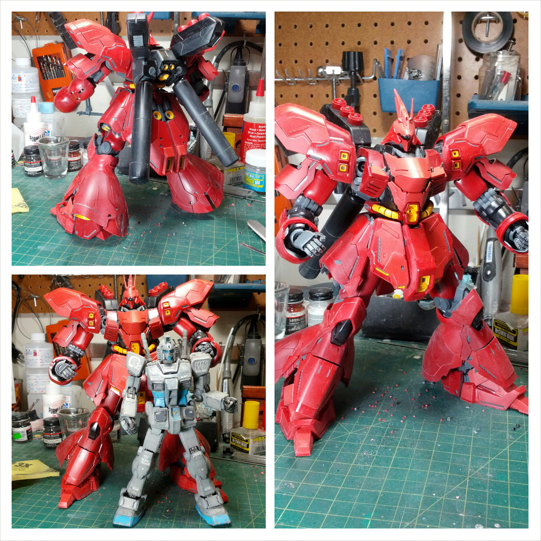
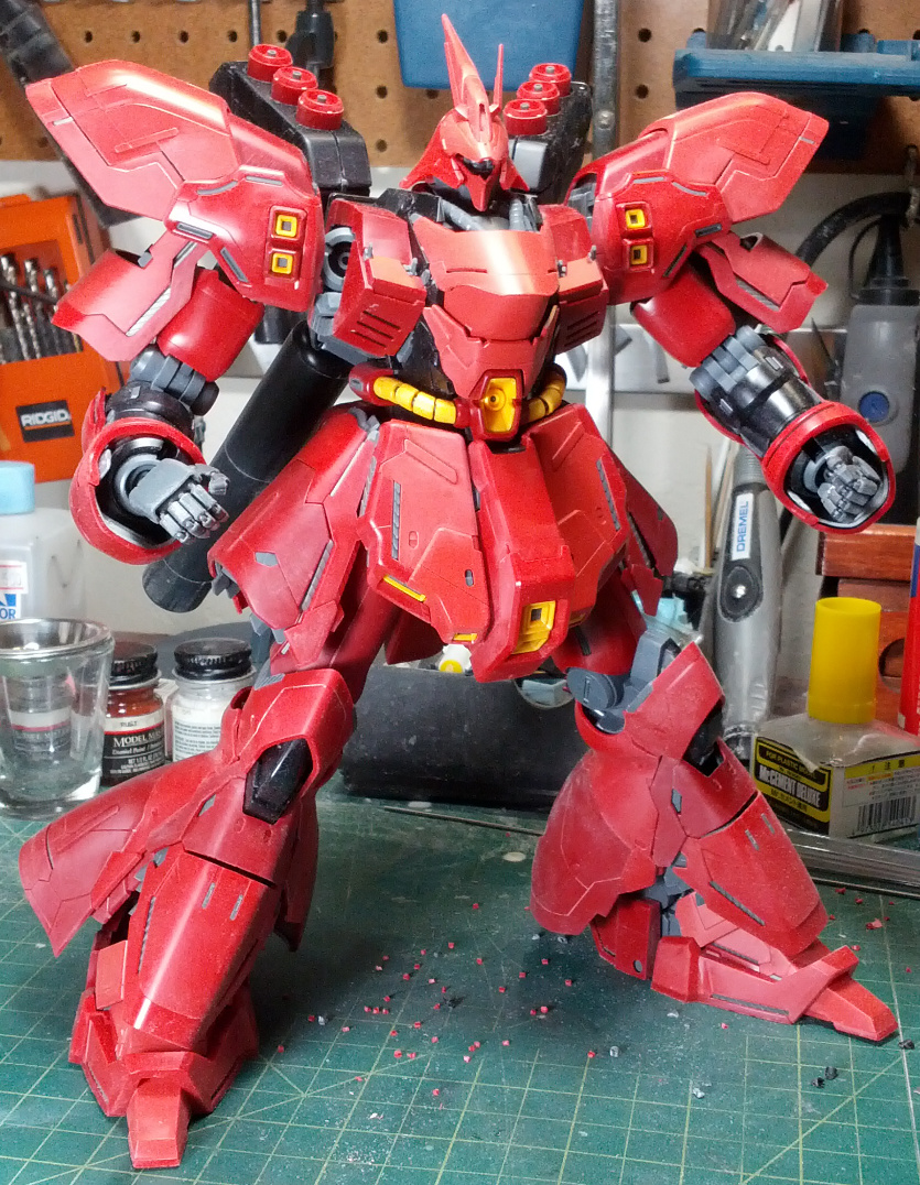
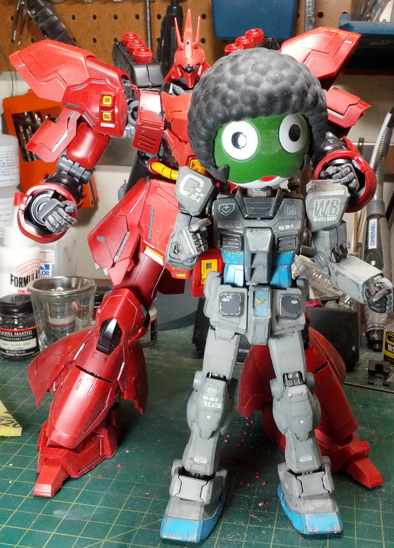
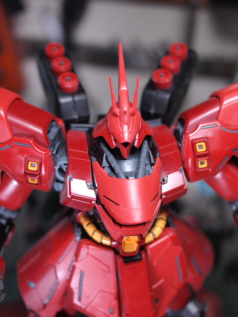
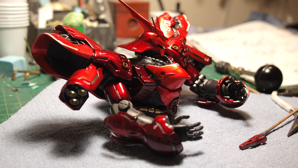
I snapped a few shots of the kit in this completed form. I have yet to build the weapons or shield. I’m still in debate on how I want those pieces displayed if at all. I’m actually quite interested in scratch building/kit bashing a new or existing weapon for the Saz either based off one of the two rifles that came with the kit.

For size comparison, good ole Keroro G3 comes out. The afro head adds considerable size that it effectively distorts the realistic size comparisons, so swapping out to the G3 head; we get a more accurate comparison. BTW, I have no idea where the damn V-fin went, but it doesn’t matter, we get a nice size comparison.

With the base kit done, I can now look at areas I want to adjust and modify. Most will be slight cosmetic mods here and there; but I’m basically looking to scale up what I did with the HGUC Saz. And I’m toying with the idea of lighting the entire kit up as well. There is so much space within the confines which allows for a bit more flexibility with wire placement and such. This should be a fun little project. Stay tuned for more updates. I’ve been regularly working on the thing and I’m pretty motivated, so this bodes well for more regular blog updates while I progress with the build.
January 19, 2014:
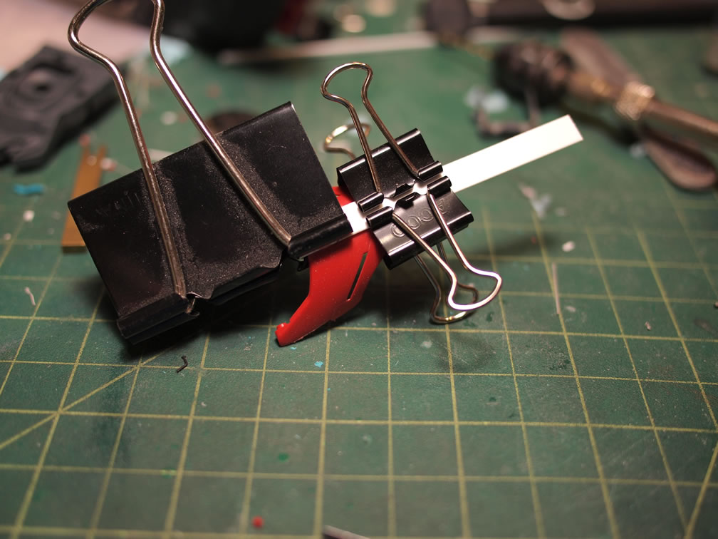
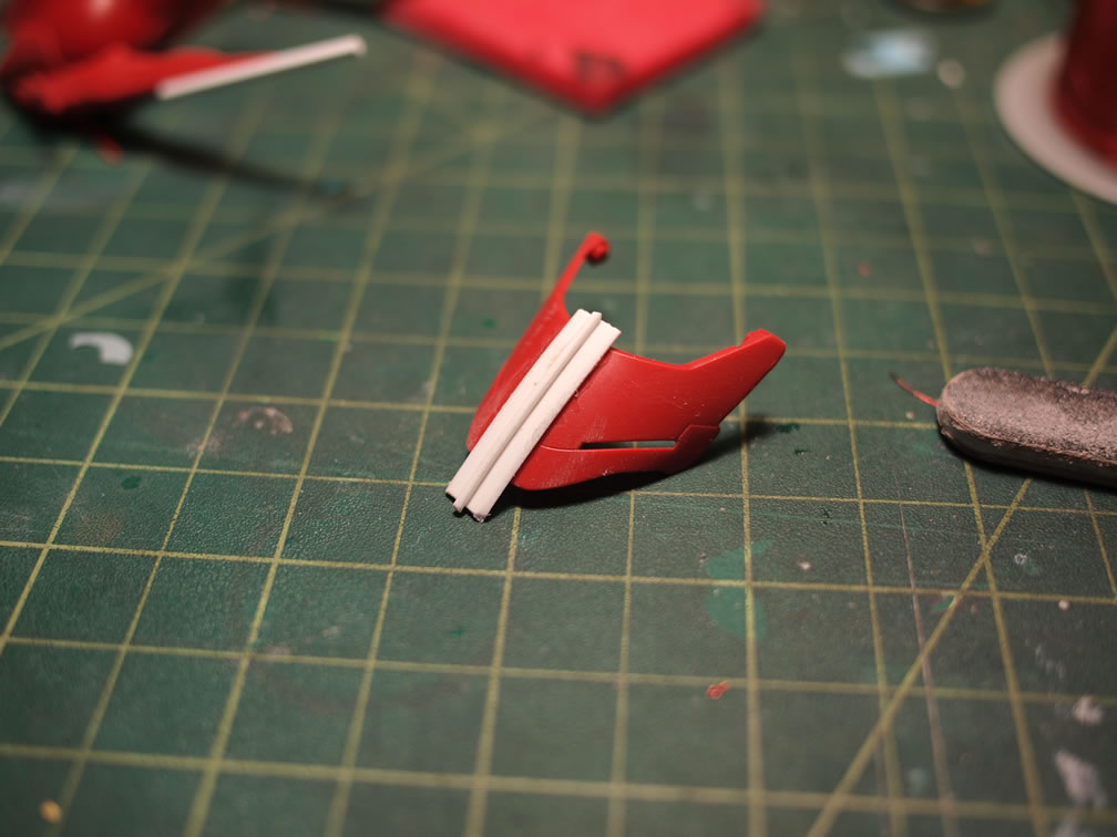
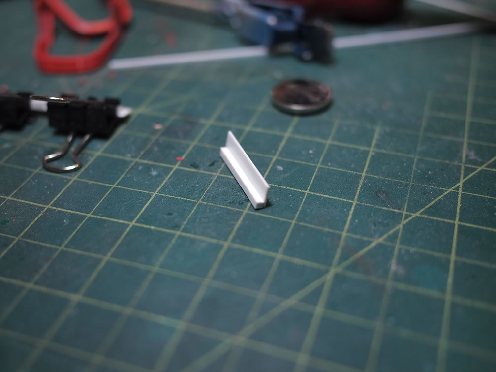
Granted this latest Sazabi kit is pretty damn nice right out of the box, but there are a few things that bugged me or things that I wanted to do, so starting off, I decided to beef up the chest. As a starting point, I used a strip of styrene, and just glued down the center line of the chest. I just eye ball this. For you engineers out there, grab the ruler, some masking tape, and a pencil; then make the correct measurements and draw in the area where the strip should go. I for one, am usually too lazy to do that and I just eyeball it. The paper clips are used to keep the styrene in place. The styrene is the base structure for the mod here. I also added an additional piece of plastic rod down the center line of the chest piece.
Once the sytrene has cured overnight, I added on some light curing putty. This is so I could work fast, as the putty cures within minutes under my work lights. The basic reshape of the chest is down with the putty over the styrene structure. Sanding sticks are used to carve out the basic shape. More styrene is glued and more putty is added and resanded.
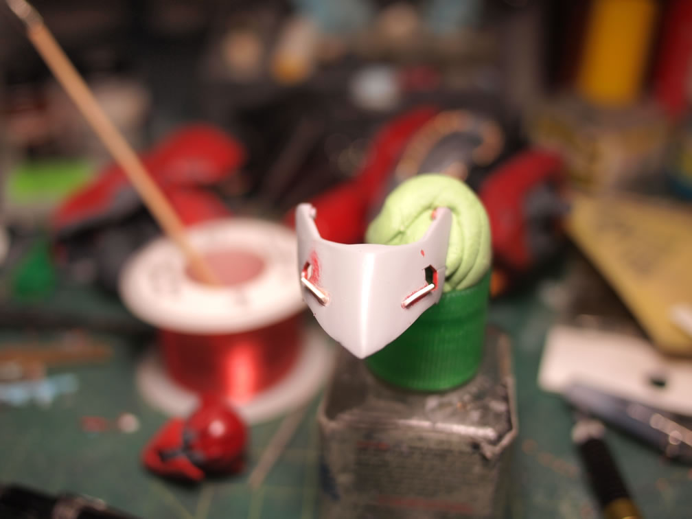
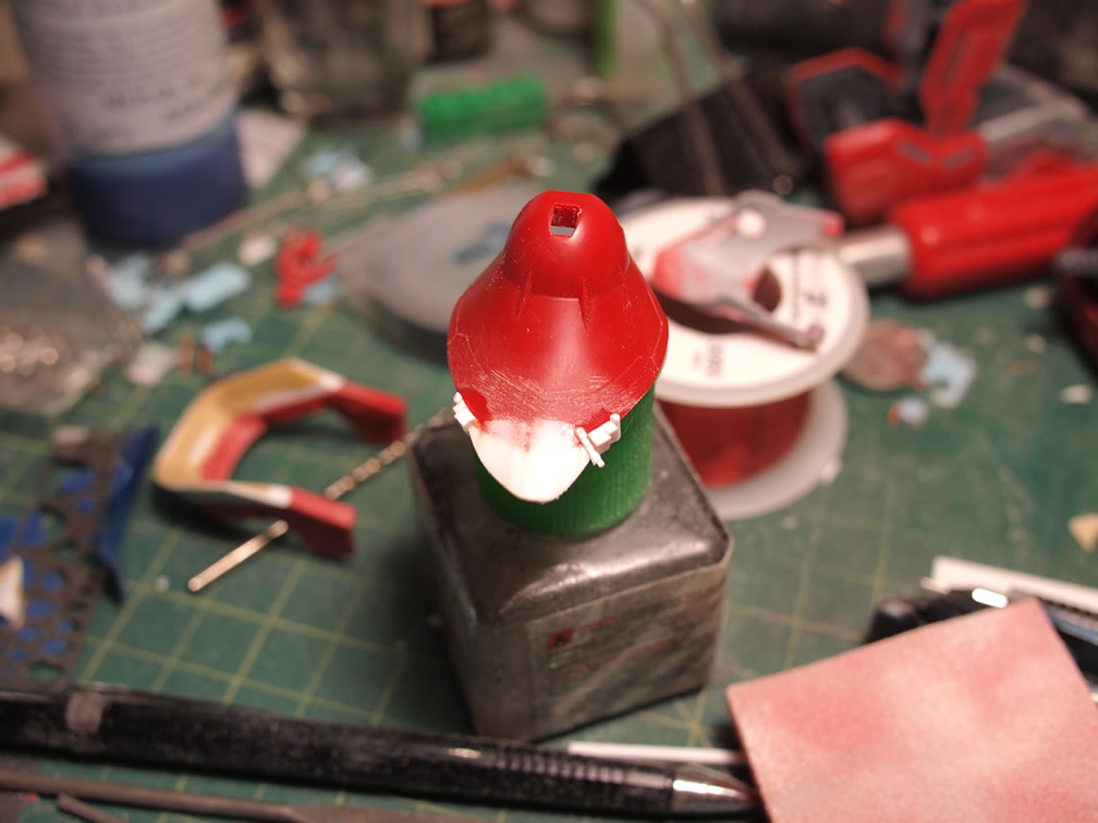
Next up, after some discussions on Facebook about the “Sleepy Dragon” face, I decided to make some mods. I drew out a hexagon on the edges of the chest slits, then glued in styrene strips into the slits. Once the glue cured, I clipped and sanded down everything.
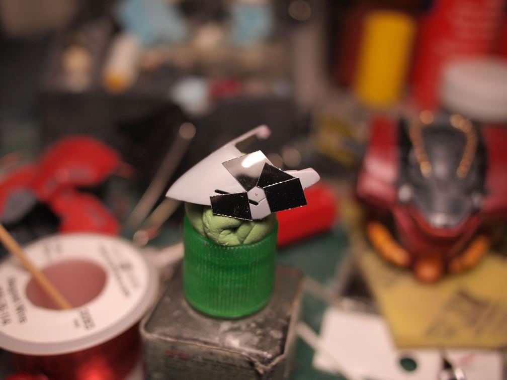
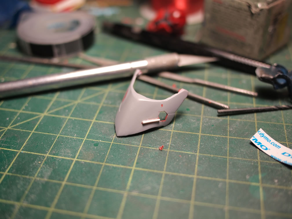
Some metal meshing was glued to the back of the chest piece, and the whole things was primed again. Since the last picture in this set was taken, I’ve sanded and re-primed a couple more time. The sanding/priming/sanding is a cycle that repeats until the part is satisfactory.
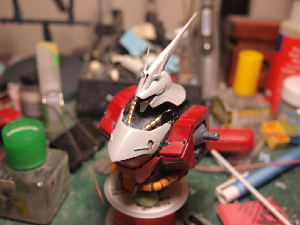
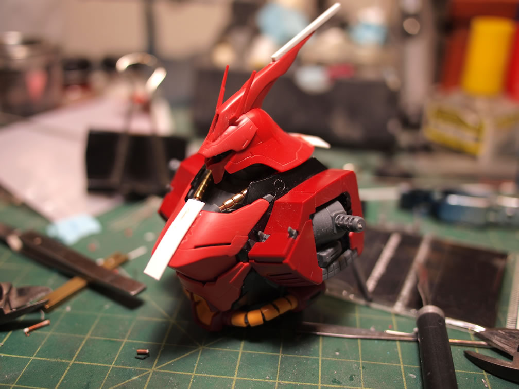
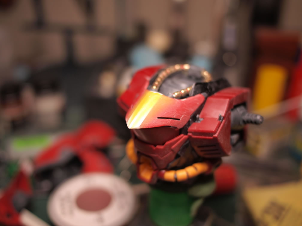
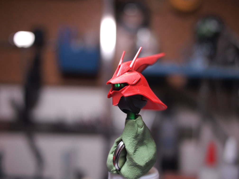
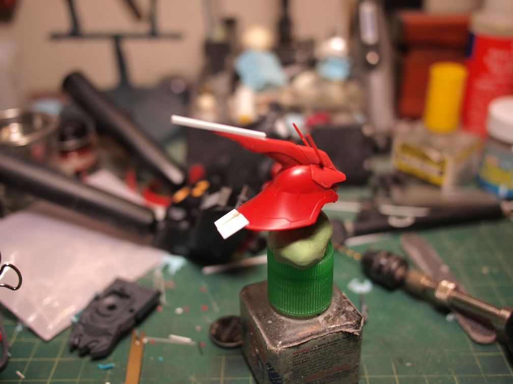
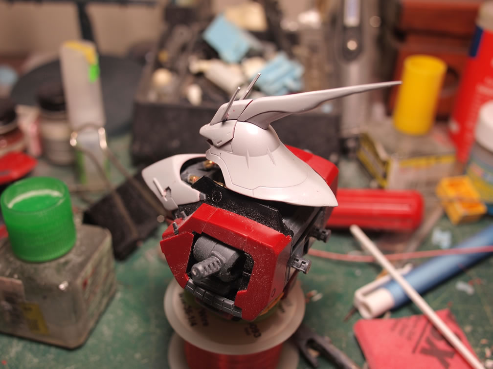
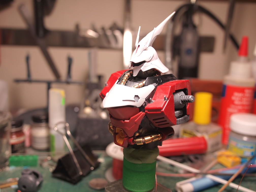
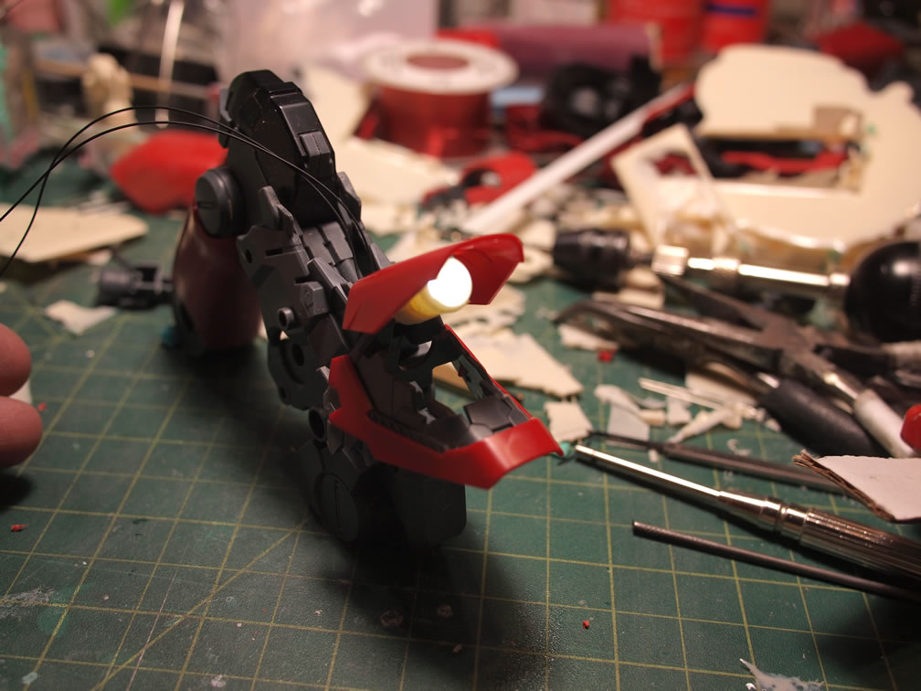
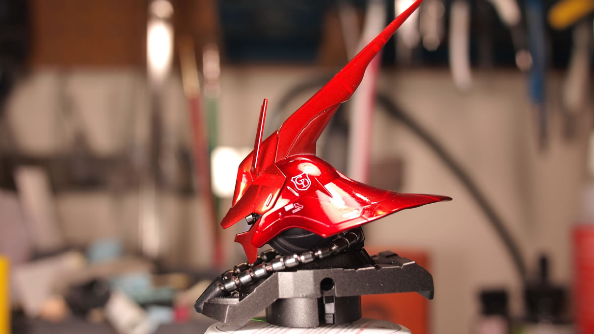
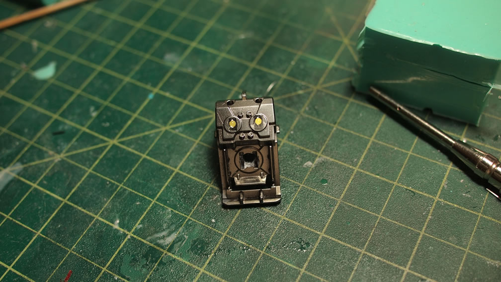
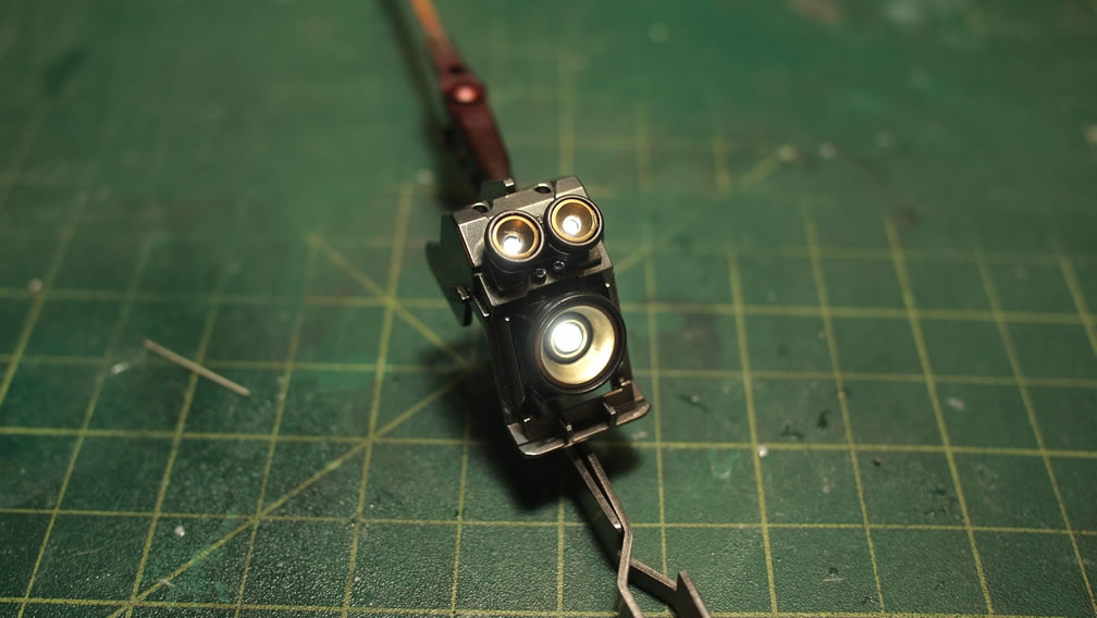
The head didn’t escape modification. The first step was to add a little collar around the bare mono eye. I like this look on all my mono-eye kits. I didn’t have a metal collar that fit, so I grabbed a plastic collar from a wave set that fit and sanded down the Saz’s clear mono eye piece to fit. Once done, I tested the look with a green LED. Not to bad looking, I will have to paint the rest of the exposed clear piece to focus the light out of the mono eye only; but the painting stage is a ways off.
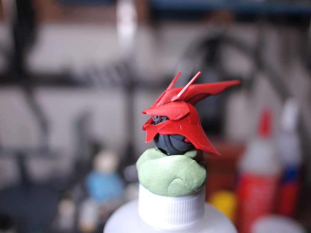
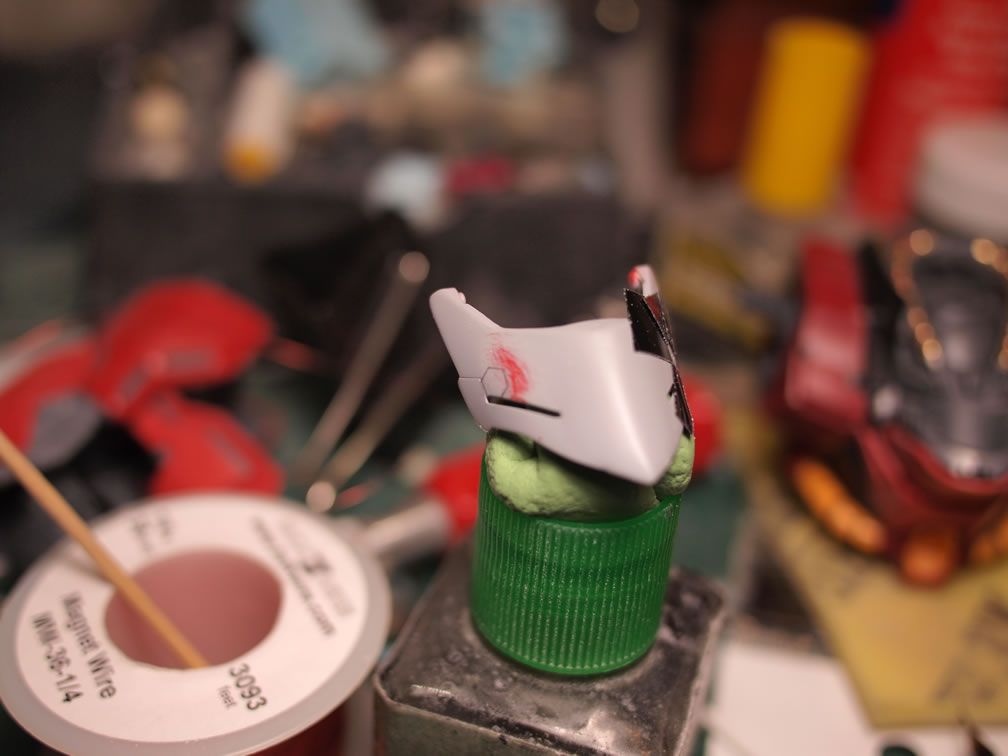
Styrene is glued to the antenna as the base structure for extension. I also glued styrene to the back of the Saz’s head. I want to elongate things. Sort of like making the back of the head similar to the Kampfer.
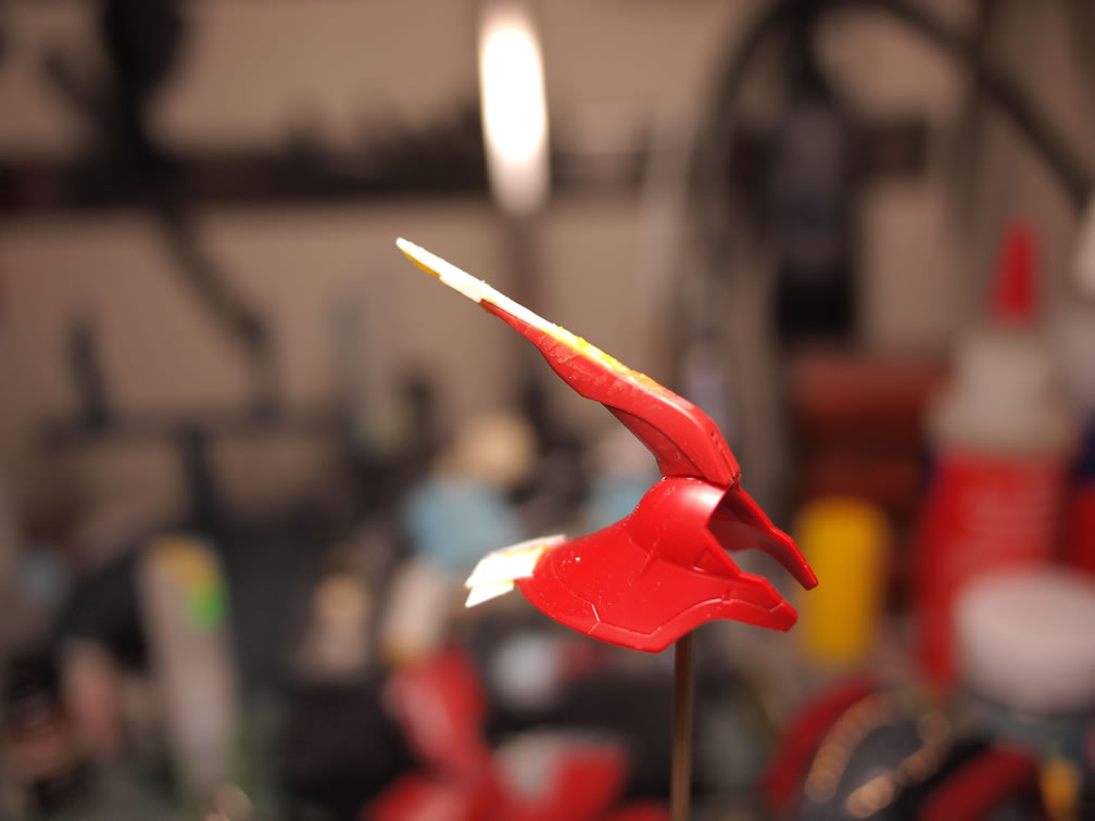
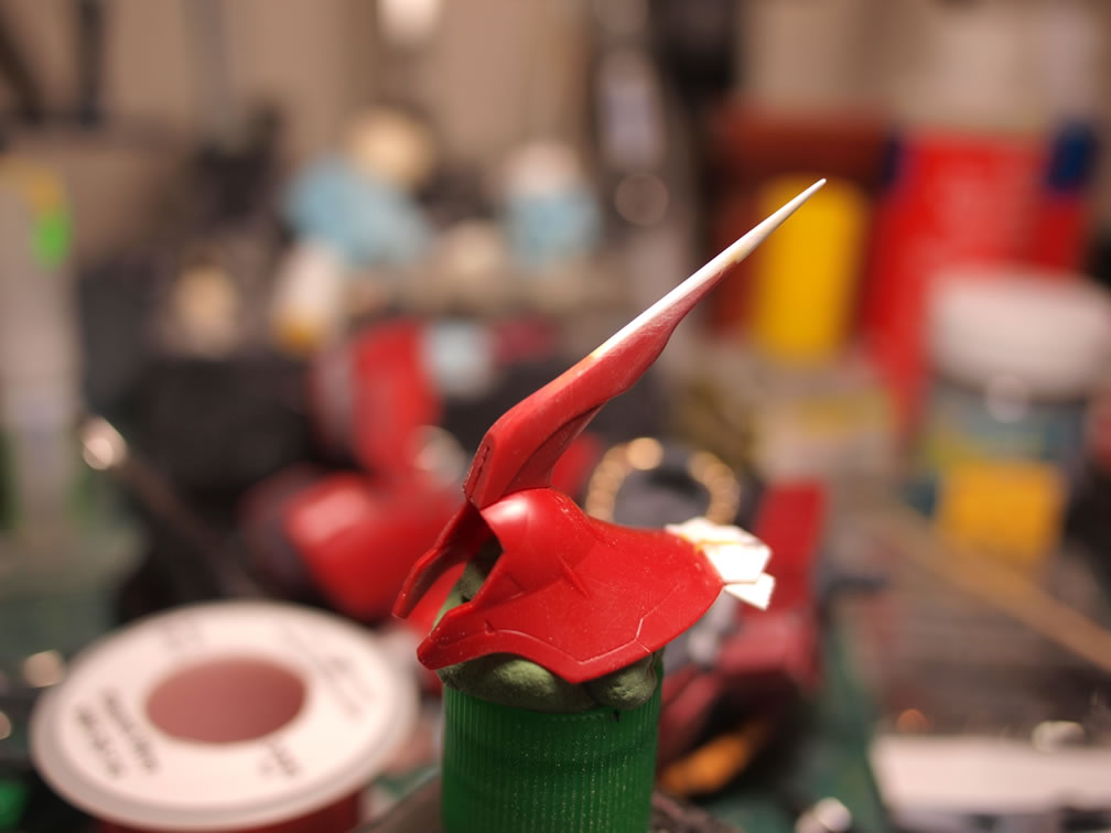
As with the chest, light curing putty, more styrene, priming and sanding are employed to get the desired shapes.

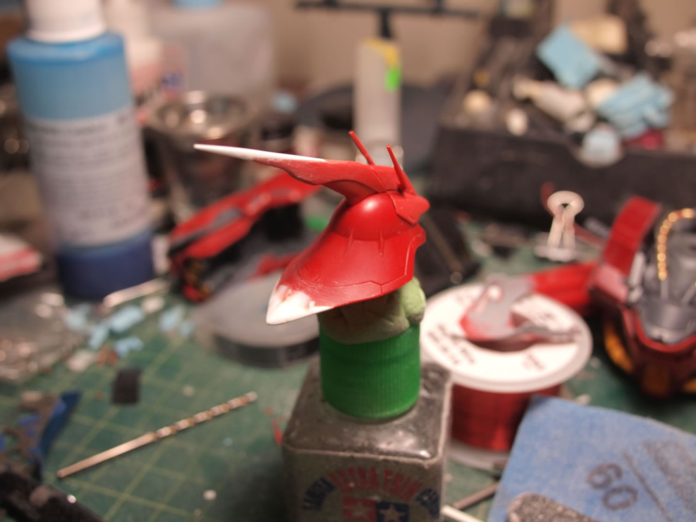
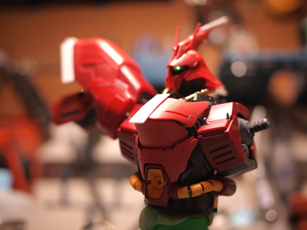
Sand, putty, repeat, and eventually, we get to the point where it’s just about ready, not quite, but the below picture should be a good enough distinction from the original kit.
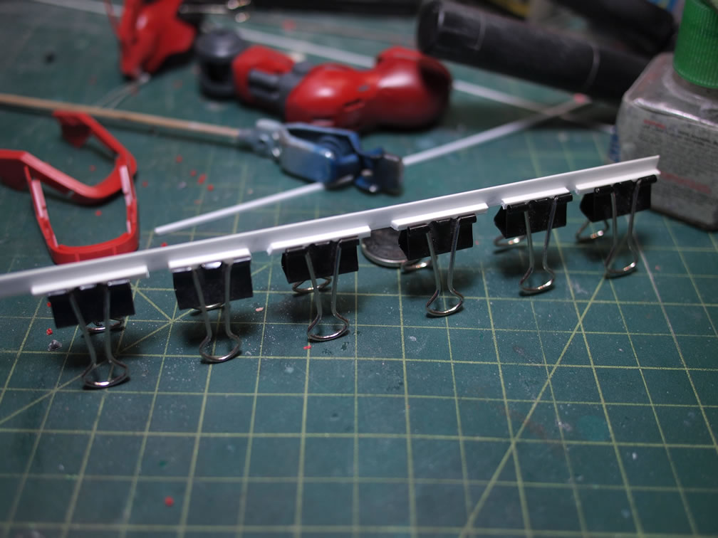
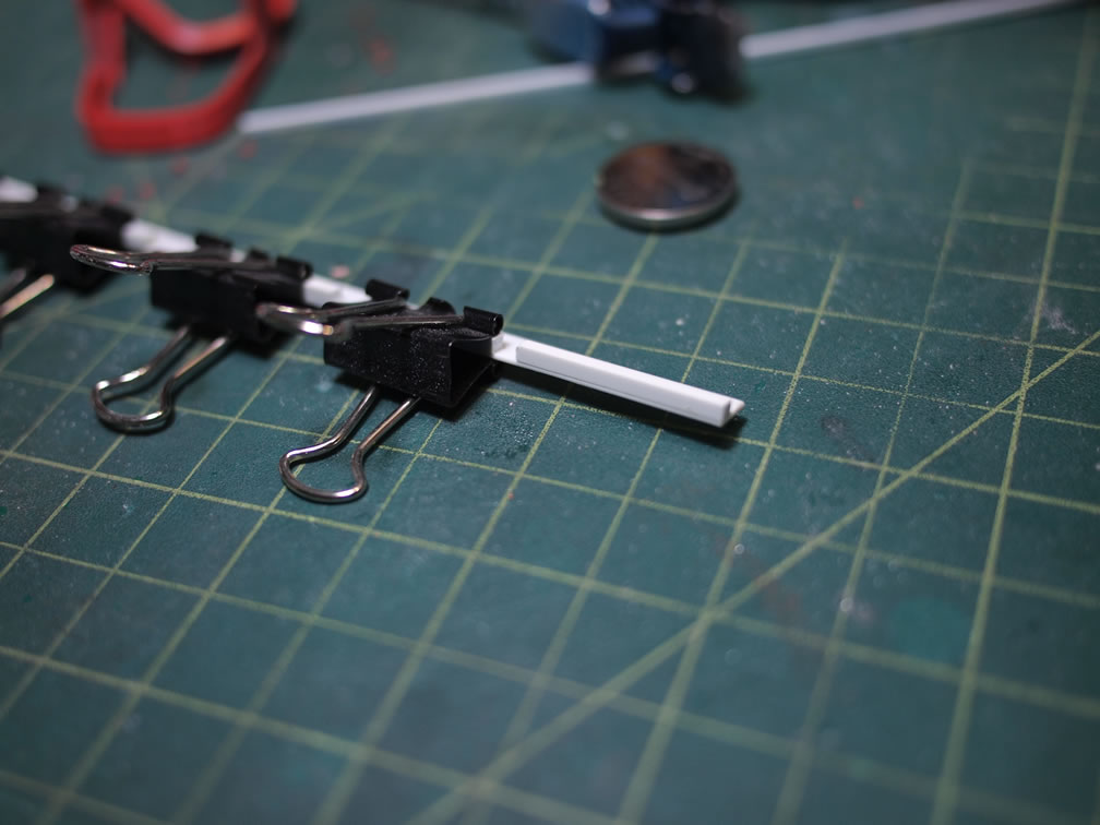
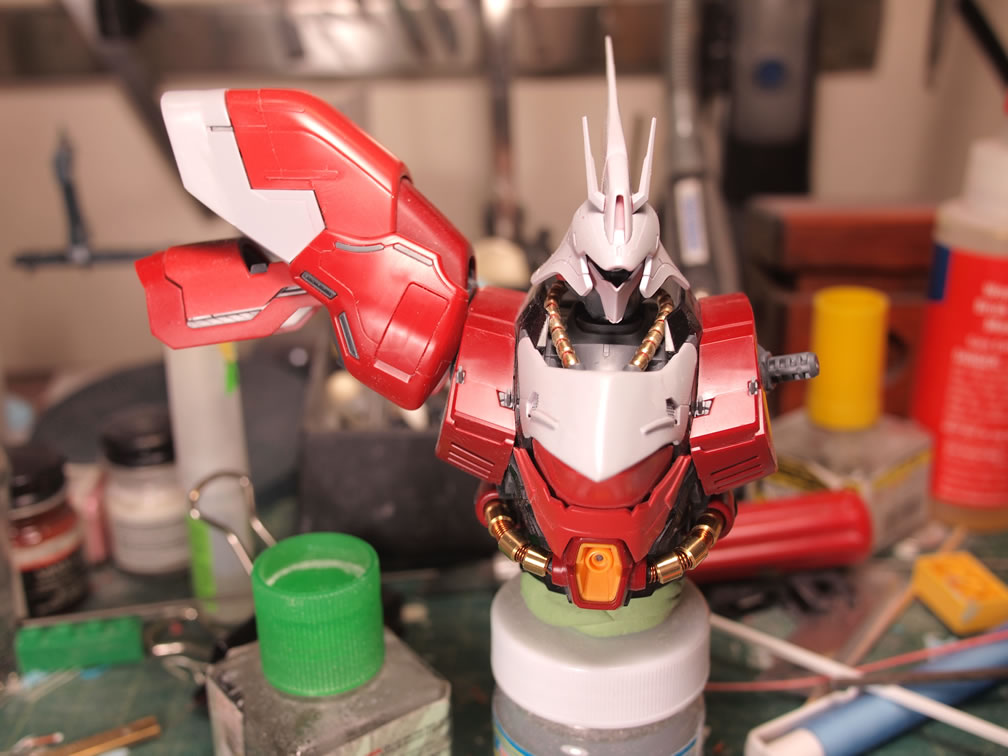
Next up are the shoulders. Since I’m beefing up the chest every so slightly, I decided to extend the shoulders and have a little bit of flaring. The first step is the basic styrene structure from which everything else is built. A strip of styrene and some styrene rectangles glued together and clamped down with paper clips. Then cut, I have the individual pieces to glue onto the shoulder ends.
Once the styrene glued to the shoulders cured, epoxy putty is used to fill in most of the gaps.
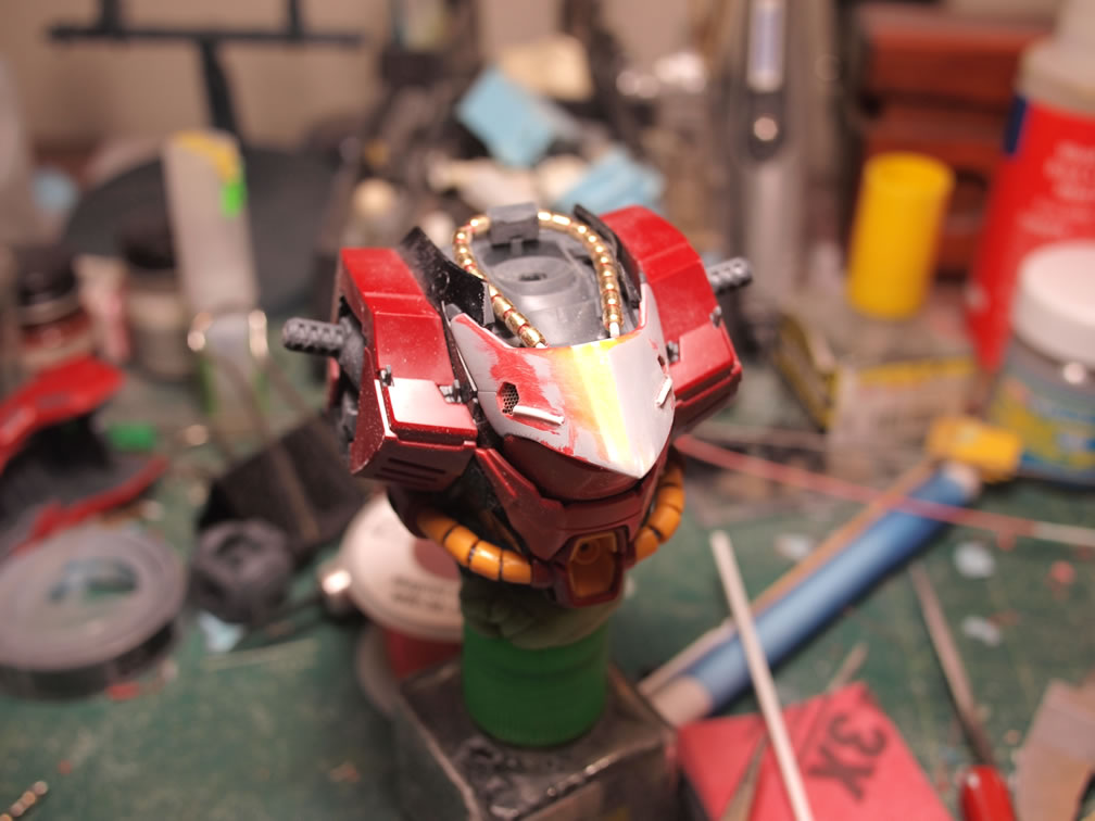
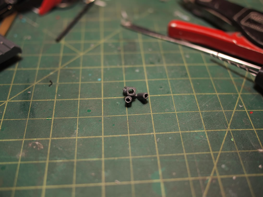
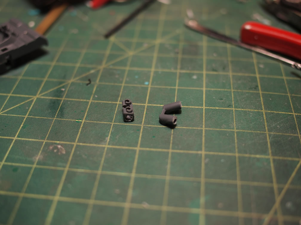
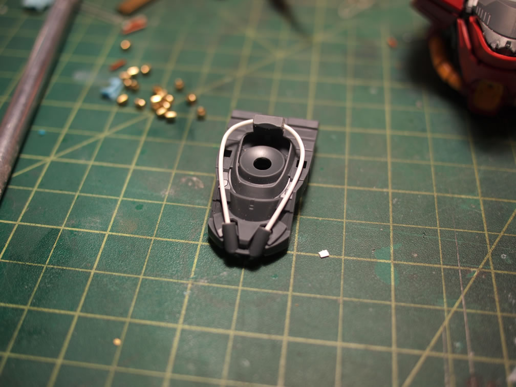
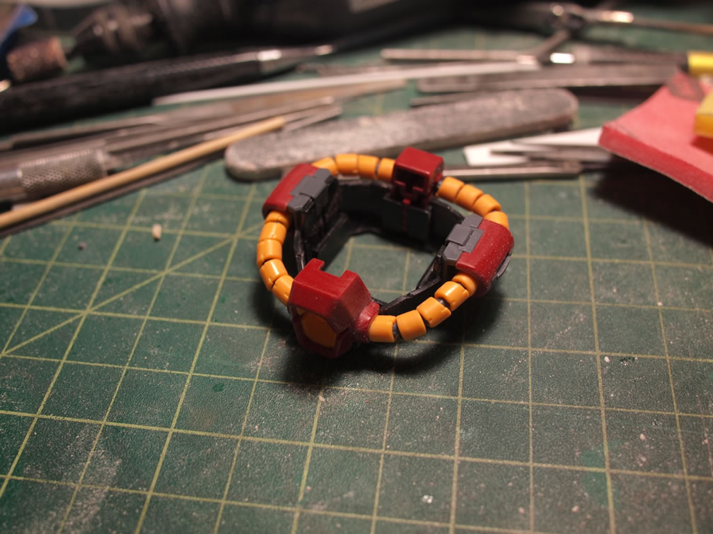
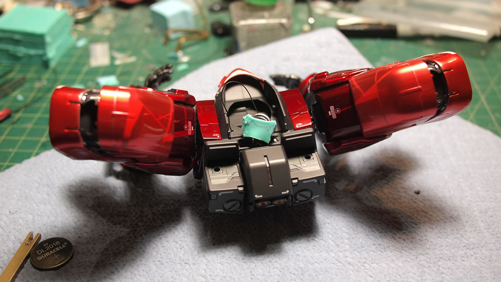
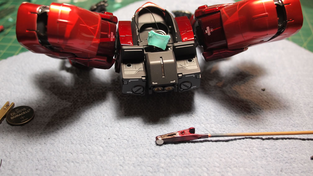
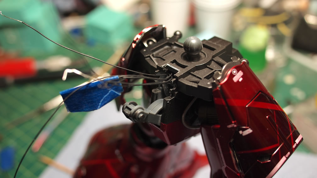
I was actually quite surprised to see that the neck cables for this kit was a single piece. This part is big enough to warrant a complete overhaul in detail. The original cables are cut from the main cable pieces. The front and back parts are then drilled out.
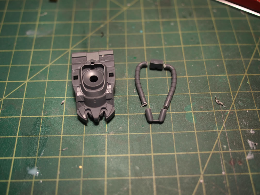
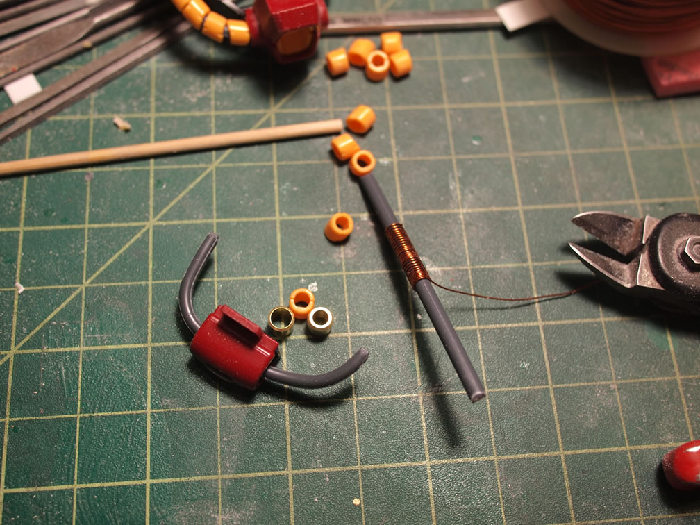
I have several shapes and sizes of metal tubes, so I found one that most closely fit. A thin styrene rod is used as the base cable structure.
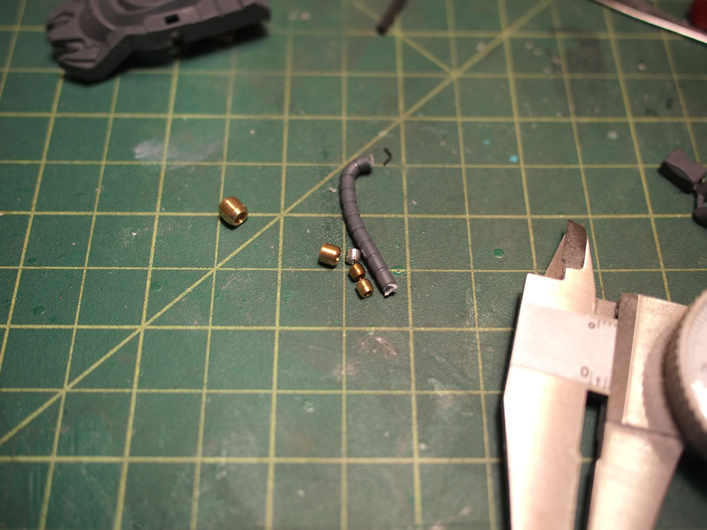
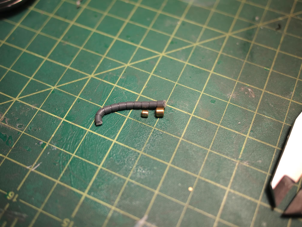
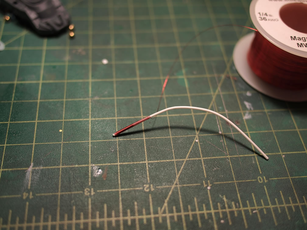
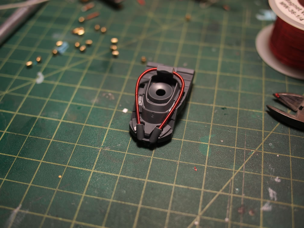
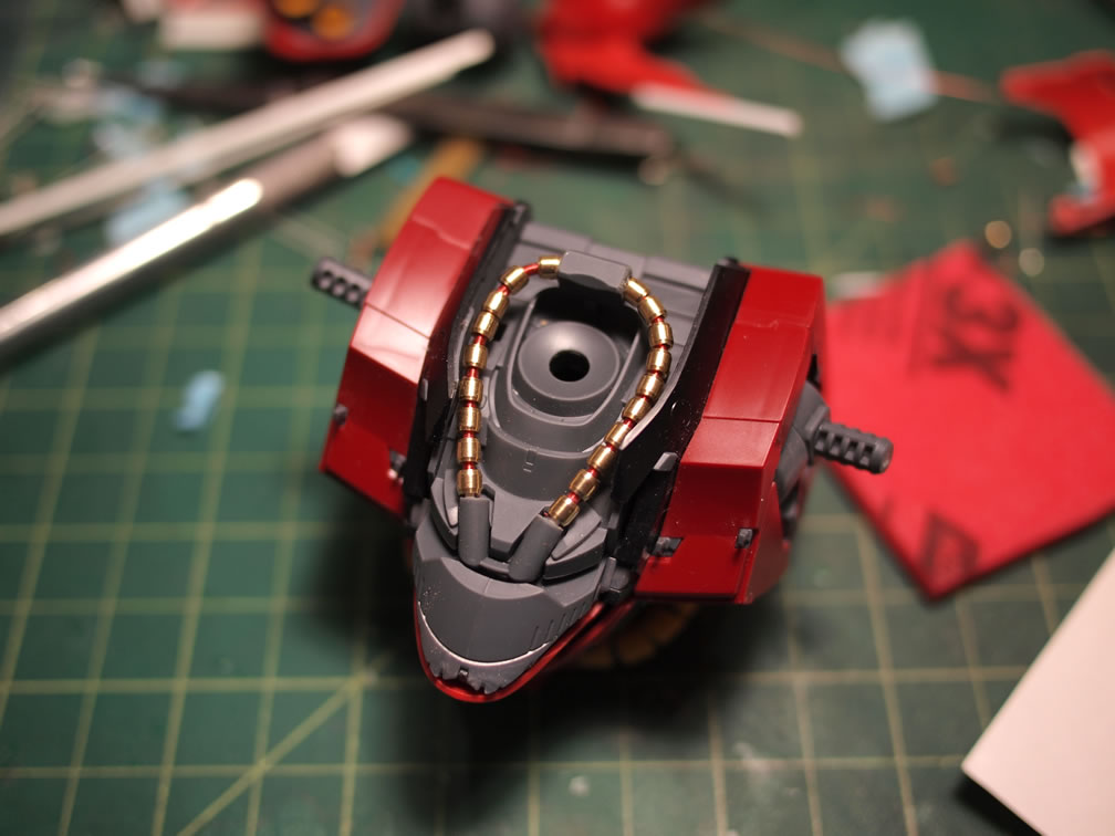
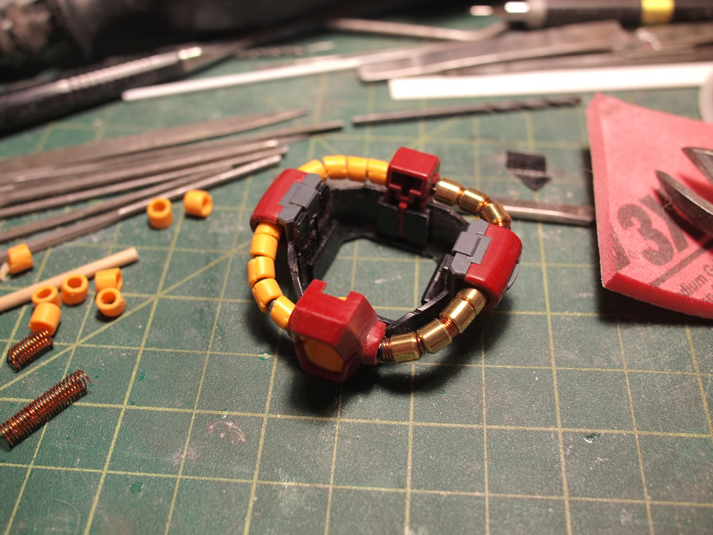
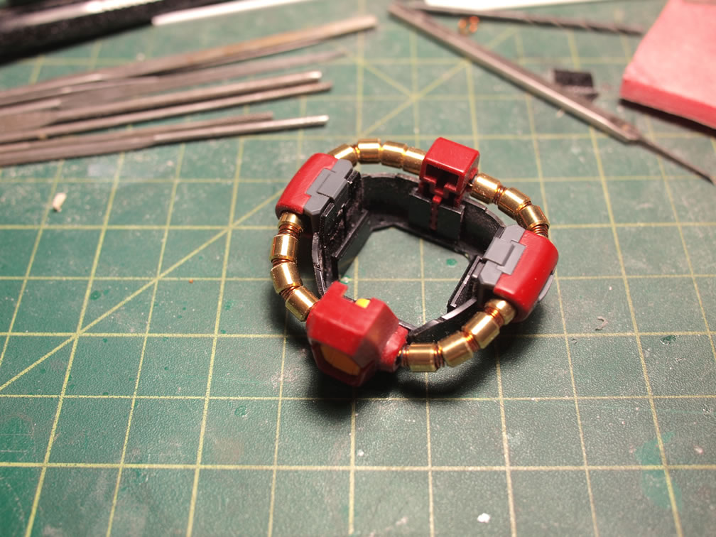
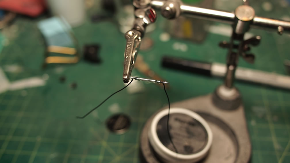
Over this base styrene rod structure, I wrapped the rod with 36 gauge magnet wire, effectively creating a custom spring. With the spring wrapped around the rod, the metal collar pieces are then glued into place spacing them slightly to show off the spring. This is a small and easy mod.
The waist cables are an even easier mod in comparison to the above mod. The original cables have molded details, but I didn’t like the fit and jiggle. Off they go.(I cannot believe I actually spent the time sanding the nubs off each of these damn cables) The original cables is kept. I found a metal collar that was only slightly larger than the originals. I used a piece of spruce from the kit and wrapped 28 gauge magnet wire around the spruce to create a larger spring. The spring was then sleeved over the original cable piece, and then the metal collars over the spring. Done. Amazingly simple.
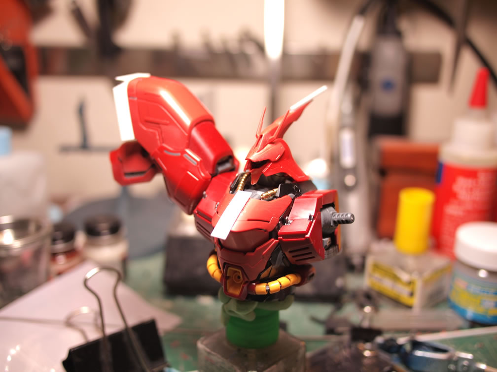
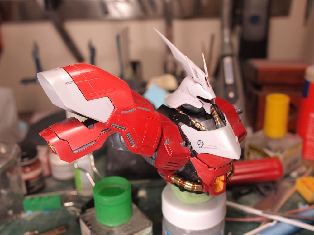
At the end of the weekend, after several cycles of putty, sand, prime, and sand. The Saz is starting to look ever so slightly different from the out of box. I have more mods in progress, and a few more ideas floating in my head. I don’t want to over do things too much as I do like the look of this design; just personalizing it a bit. Here’s the kit’s progression so far.
February 3, 2014:
Time for another Ver Ka Sazabi update. Today’s update will cover the process of making LED embedded resin thruster parts. The why of it all, well, we’ll get into that later. Going back to when the kit was sanded and dismantled; the thruster pieces were singled out and I started to plan out the process for adding some lighting mods. I had lit the HGUC Sazabi, so I figured this much larger scale shouldn’t be much of an issue. My experience from working with lighting the 1/144 scaled Sazabi helped make my decision on the direction.
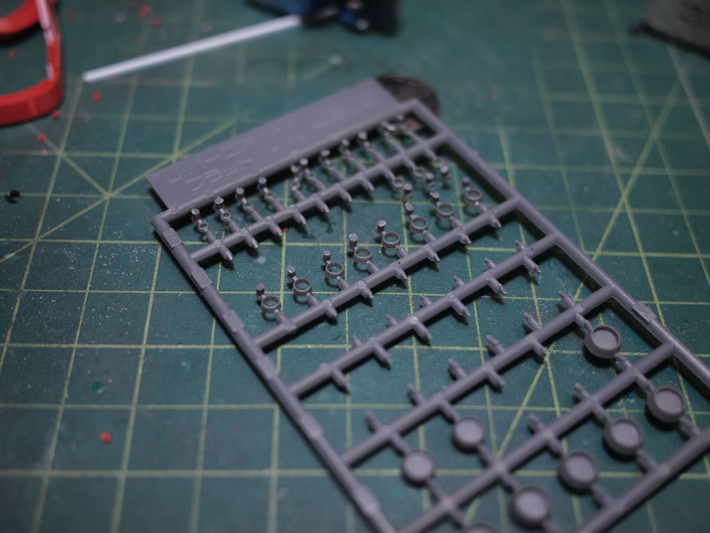
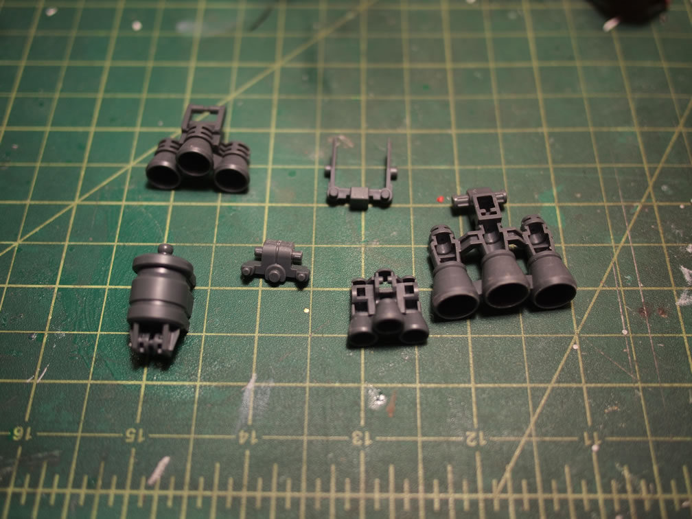
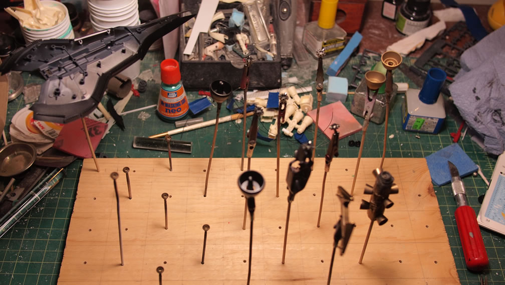
Seven thruster parts are identified. Granted, I’m ignoring the square thruster pieces all over the body, as well as the round one at the back skirt – there’s something to be said about going overboard with lights. And these seven, effectively 14 thruster pieces should be enough for the effect.
With these seven thruster parts picked out, the LED count for just the bells is 32. Lets do this!
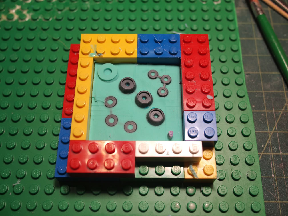
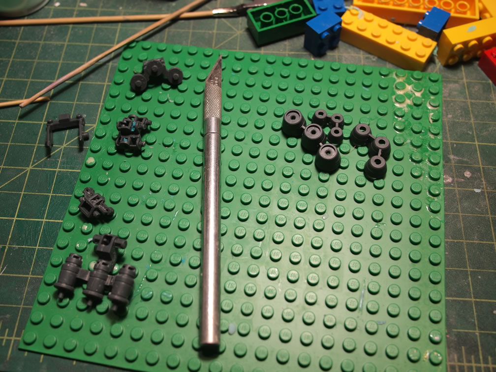
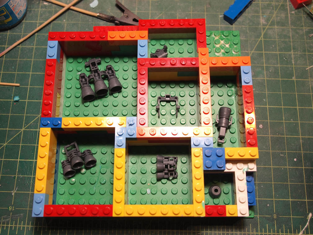
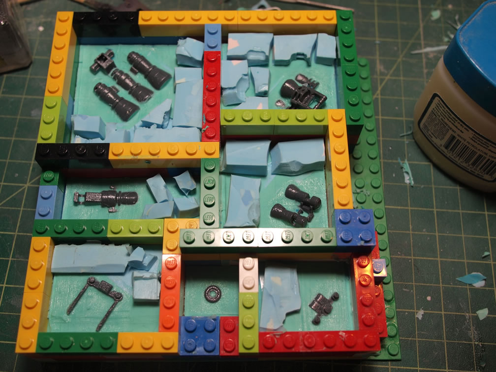
The first step, again, from my experience with the lil’ Saz is to make molds of the bells first. The bells are gathered and placed into a Lego enclosure. Legos are great for mold making as you can get various block and fairly water tight seals, water tight enough for the silicone in liquid form. The bottom of the square blocks is filled with a layer of play dough. The thrusters are placed on top of this layer of play dough. The play dough acts as an anchor for the parts as well as a stop zone for the silicone.
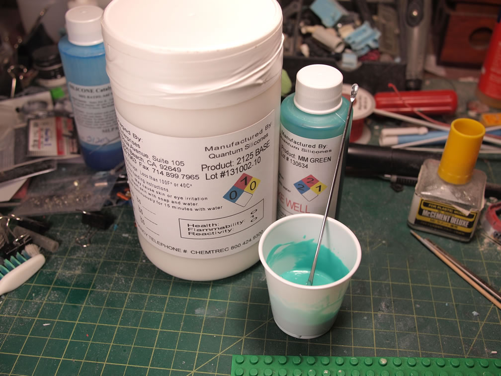
I’m using is a green 25 duro silicone. Mixed by weight at a ratio of 10 to 1, rubber to catalyst, the molds are poured and pressurized to reduce air bubbles. Once one side is made, the play dough is removed and the mold with the thruster bells are washed and dried. Vaseline is lightly brushed over the side that was sealed with the play dough and replaced into the Lego blocks, and the second half of the mold is poured.
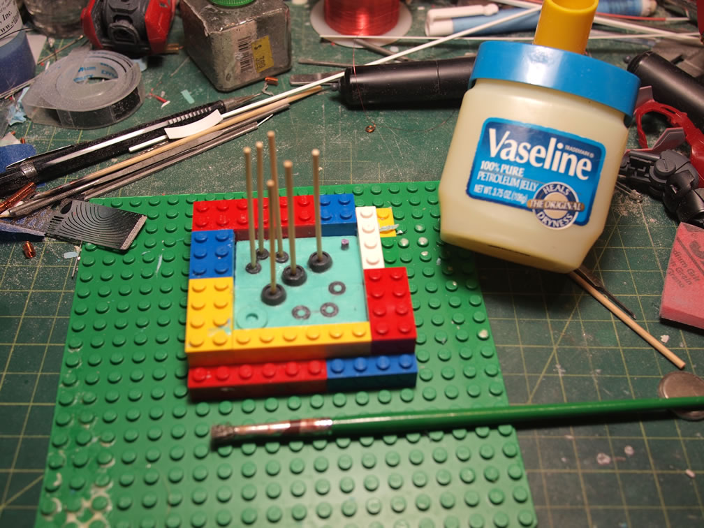
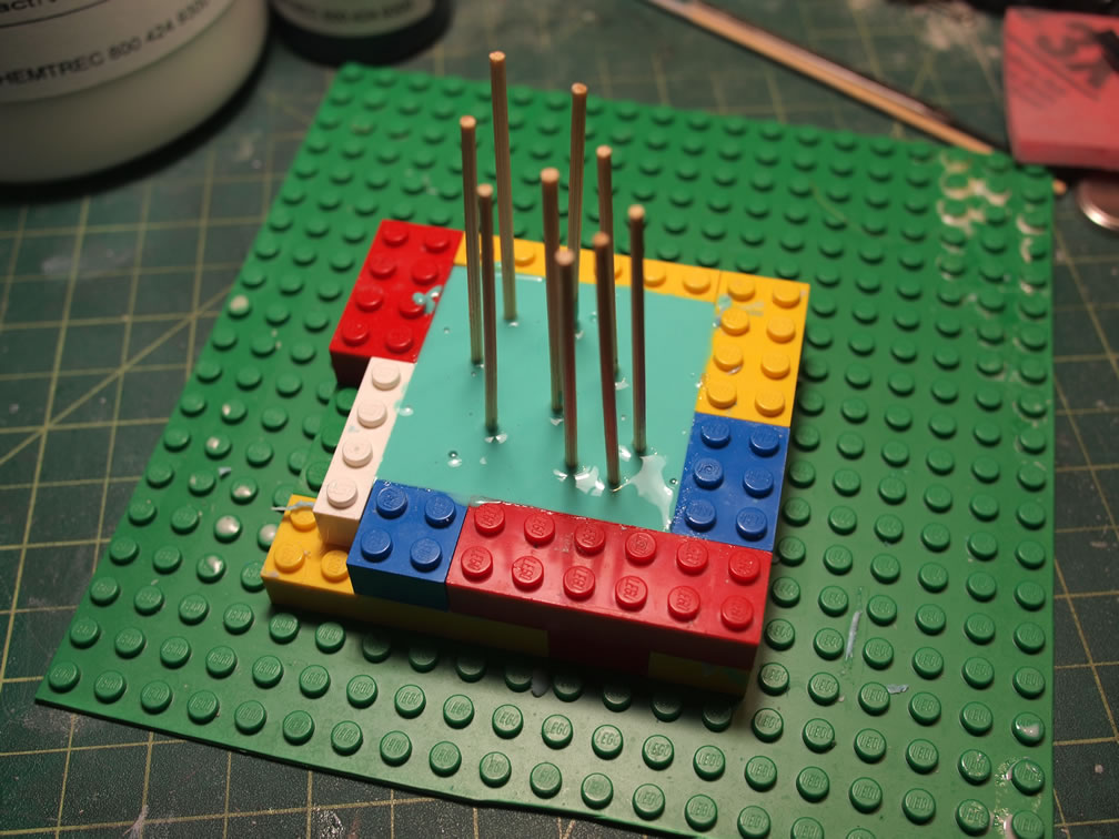
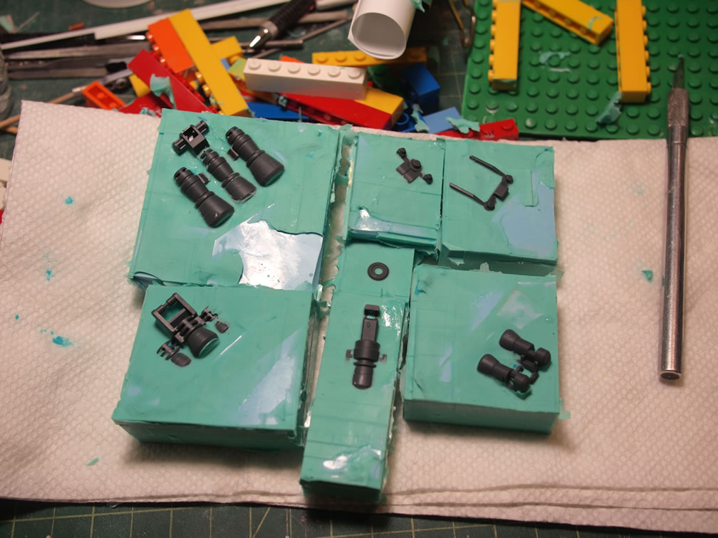
Part orientation and how you mold/cast a part is very important to making things more difficult or easier. It would have been much easier to cut and sand down the thruster bells that were connected together. Live and learn. Now for the main part pieces, the bells are glued into position for as airtight/water tight seal as possible. Then placed onto a play-dough bed with bits of cut up cured silicone from older molds as filler materials. This is the first section of a planned two part mold.
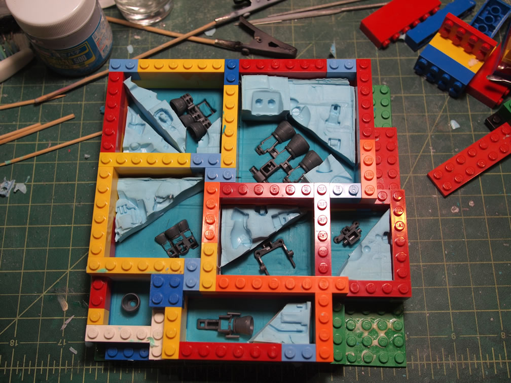
As explained with the thruster bell molding, the first part of the mold is removed from the lego encasing and the playdough under layer is removed. The mold is then washed and dried and prepared for the second silicone filling of the two part mold.
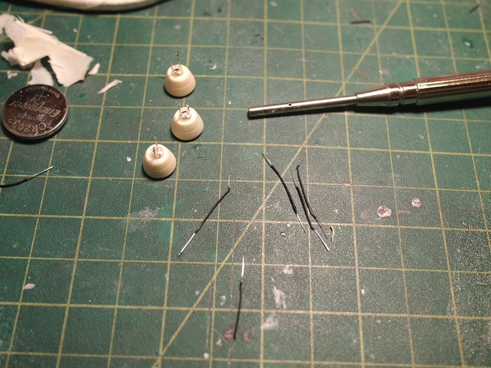
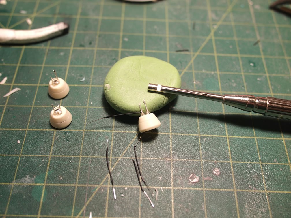
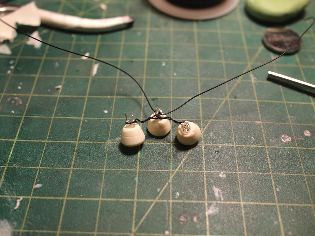
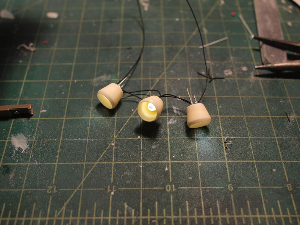
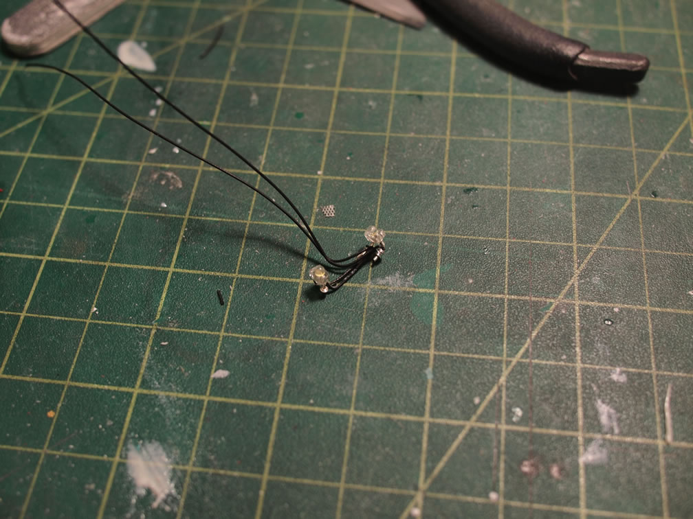
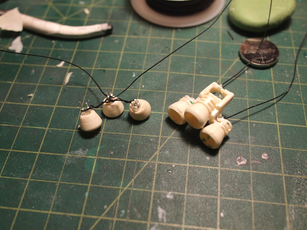
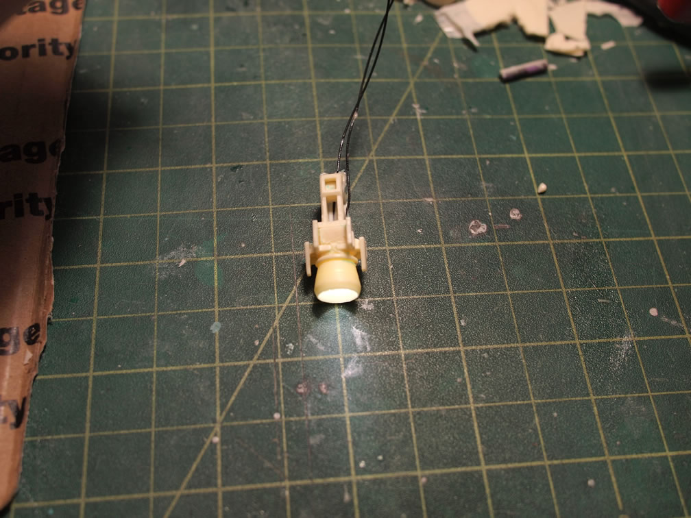
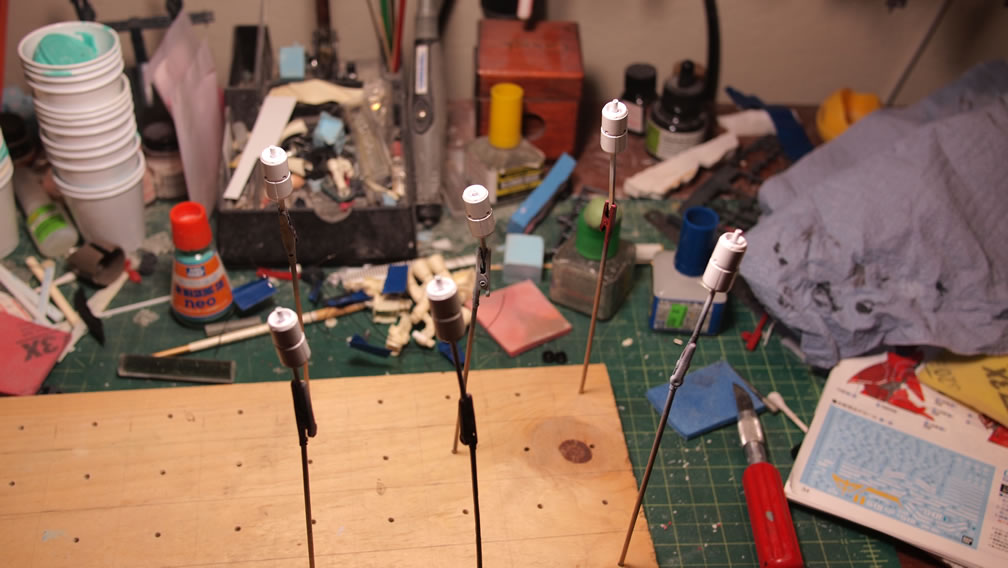
The thruster bells are cast and cleaned up. LEDs are then glued to the thruster bells. In some cases, the LEDs will fit nice and snugly into the thruster bell holes, but again, to ensure as water tight a seal, they are best glued. One thing I learned in this gluging process is that one should never use CA glue with LEDs. The CA glue makes the LED body brittle, and slight amounts of pressure will break the LED. I now use a 5 minute epoxy glue to attach the LEDs to the thruster bells. Once the glue has set and cured, the LED leads are trimmed and wired to one another in parallel.
This brings about the point on wire planning. Depending on the power source and the power requirement of the LEDs (each color has different power requirements), I can wire the LEDs in series or in parallel. Math is involved here. Since I want the power source to be self contained inside the kit, I will be using a smaller power source which then dictates that the parallel wiring scheme best fits my situation.
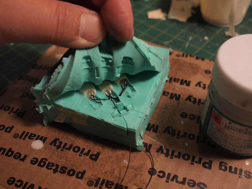
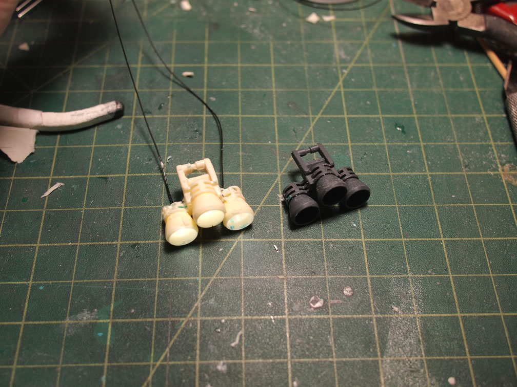
Once the LEDs are wired, the entire assembly is place bell/LED assembly into molds. Since I cast the parts with the bells glued, I can now place the LED bell assembly into the bell portion of the mold. The rest of the mold is filled with a 2 part resin mixed by weight at a ratio of 1 to 1. The 3 minute resin is quickly placed into the pressure pot before it starts to cure.
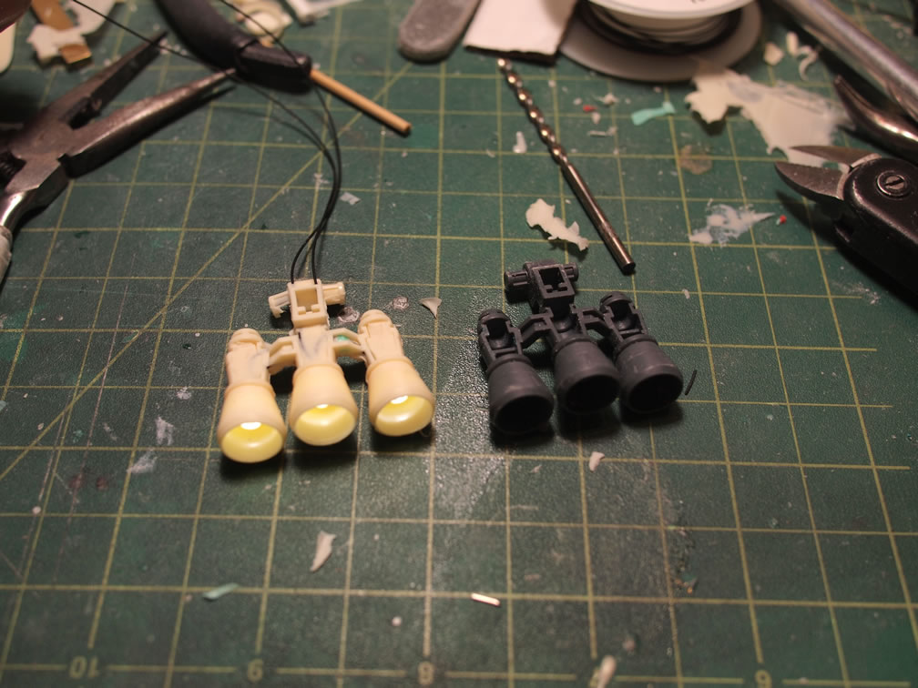
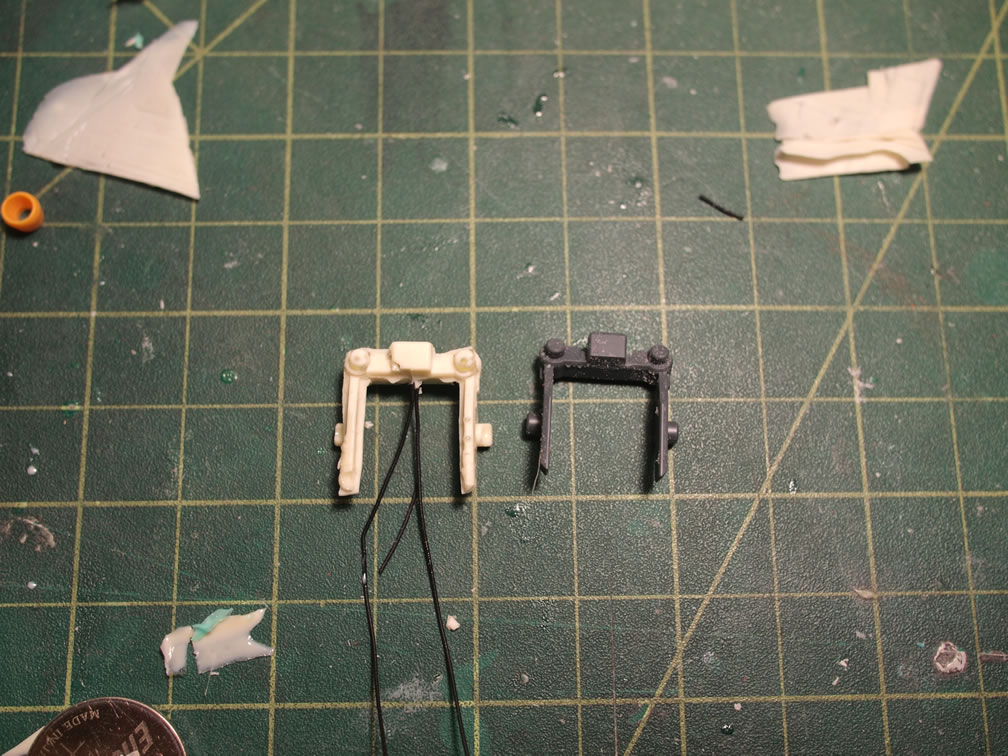
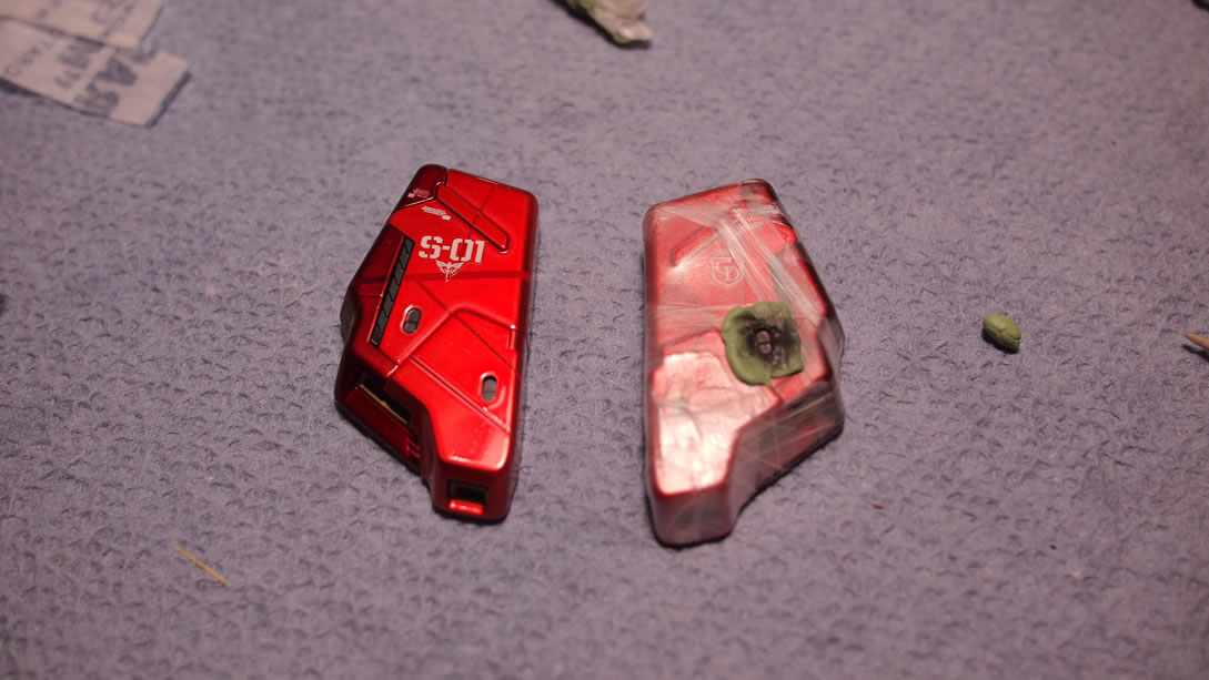
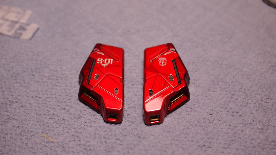
Once the parts are demolded, the part is tested to make sure the LEDs are still working. Here is a comparison of the original part and the cast part. For this particular piece, I decided to use the original bells. This was decided at the mold planning.
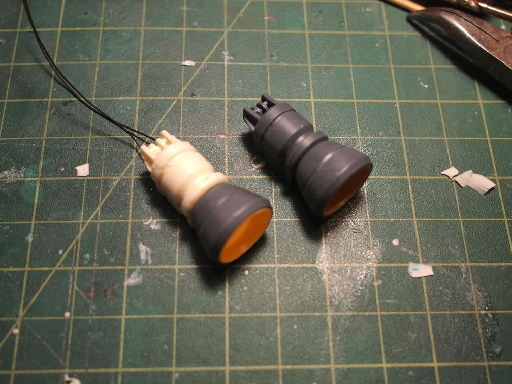
The process is then repeated for the rest of the thrusters. Some parts were similar in design and hence easier to plan and cast, others needed some reevaluation and a redesign in the mold.
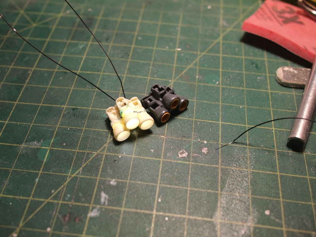
So at this point, I’ve done all this work to replicate the parts with embedded LEDs. It would have been just as easily to drill some holes and pop the LEDs into the original parts. Now I’ll attempt to answer the begging question, Why bother with all this casting?
Again, from my experience with the smaller scaled Sazabi, I found that some parts, no matter how much drilling or putty, would just been too difficult to add LEDs, some of the smaller parts such as the forearm thrusters and the upper shoulder thrusters (both of these a specific add to the original Saz design). I have also found that once I had all the LEDs wired up and attached to the original parts, I had a mass of wire s and LED bodies protruding from the original parts. And I have to do this custom work to both sides, which significantly lowers the possibility of getting close to identical parts.
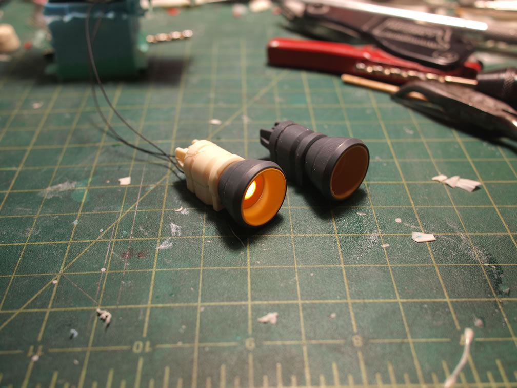
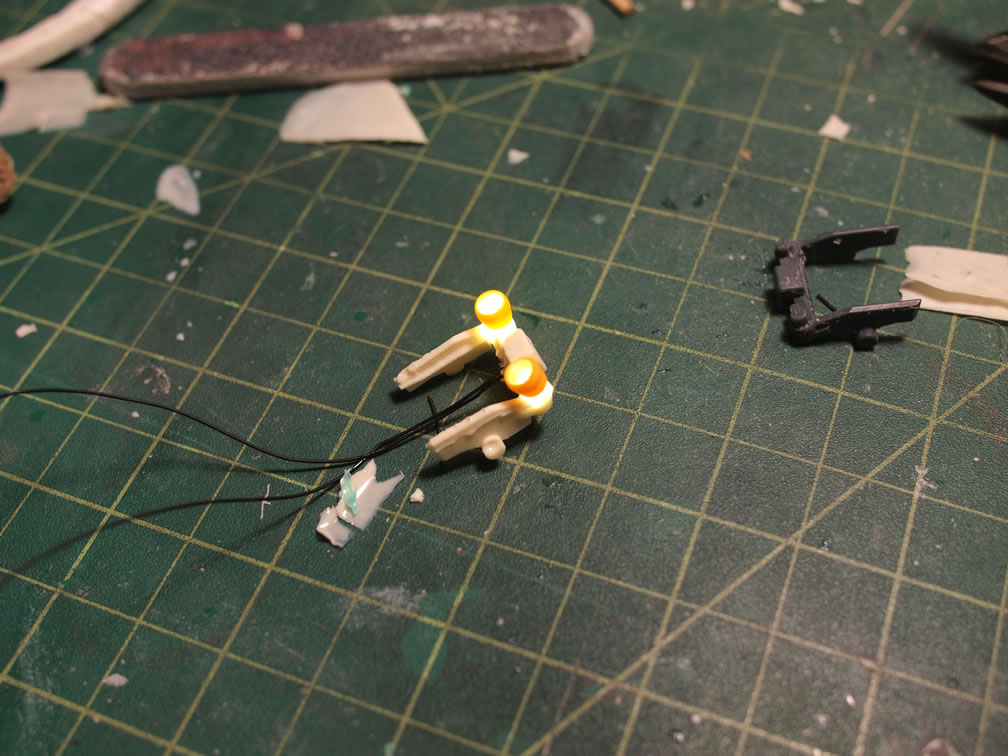
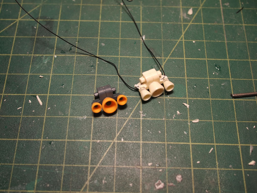
Solution, cast the LEDs inside the parts. No drilling in to the originals. I can make multiple copies that are close to identical. All the wiring between the LED sets are hidden inside the resin. Looking at the below example, the part is then just plugged in with little to no modification needed on the original connecting piece.
If that doesn’t sufficiently answer the why for some folks, well, then because I could, so I did.
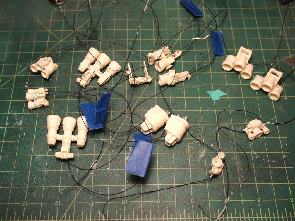
All said and done, 7 different parts molded, which equated to 14 total parts being casted for the suit using 32 individual LEDs – yeah this took a while. I’ve been documenting the process from the start of work on this model. I’ve decided to take the approach of posting completed sections, or as close to completion as some modification processes can get. This sort of keeps the focus on certain aspects of the build with out jumping all over the place. It’s good to be organized I guess.
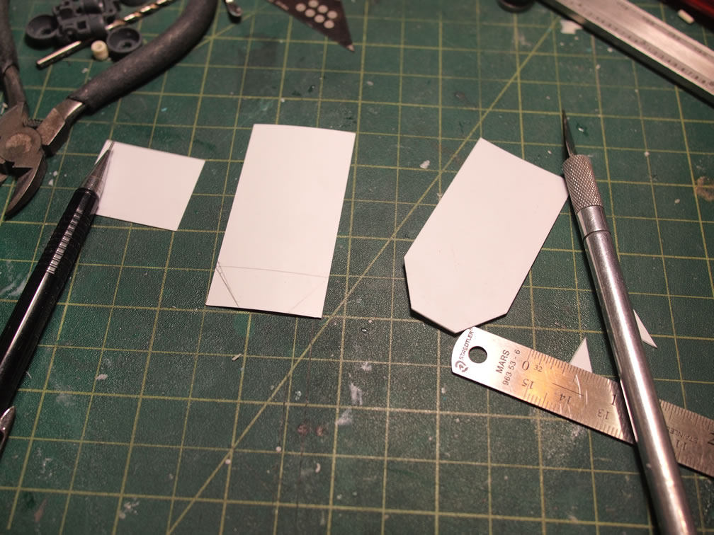
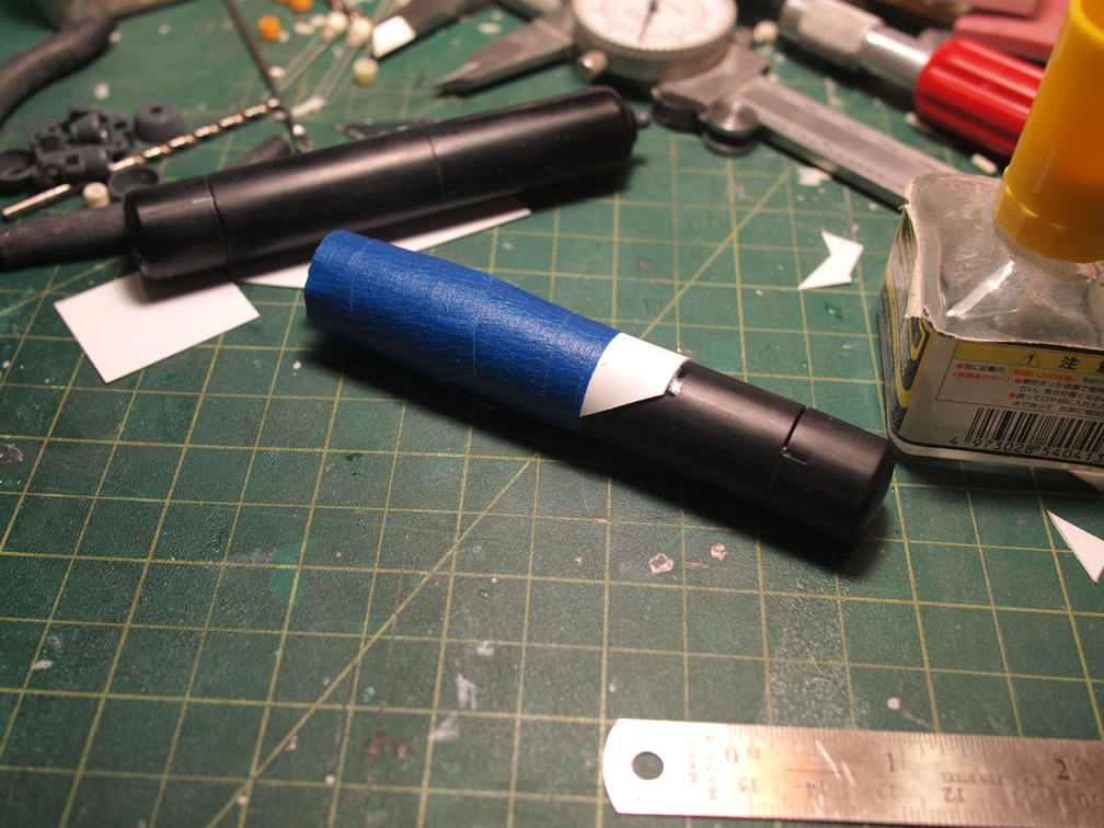
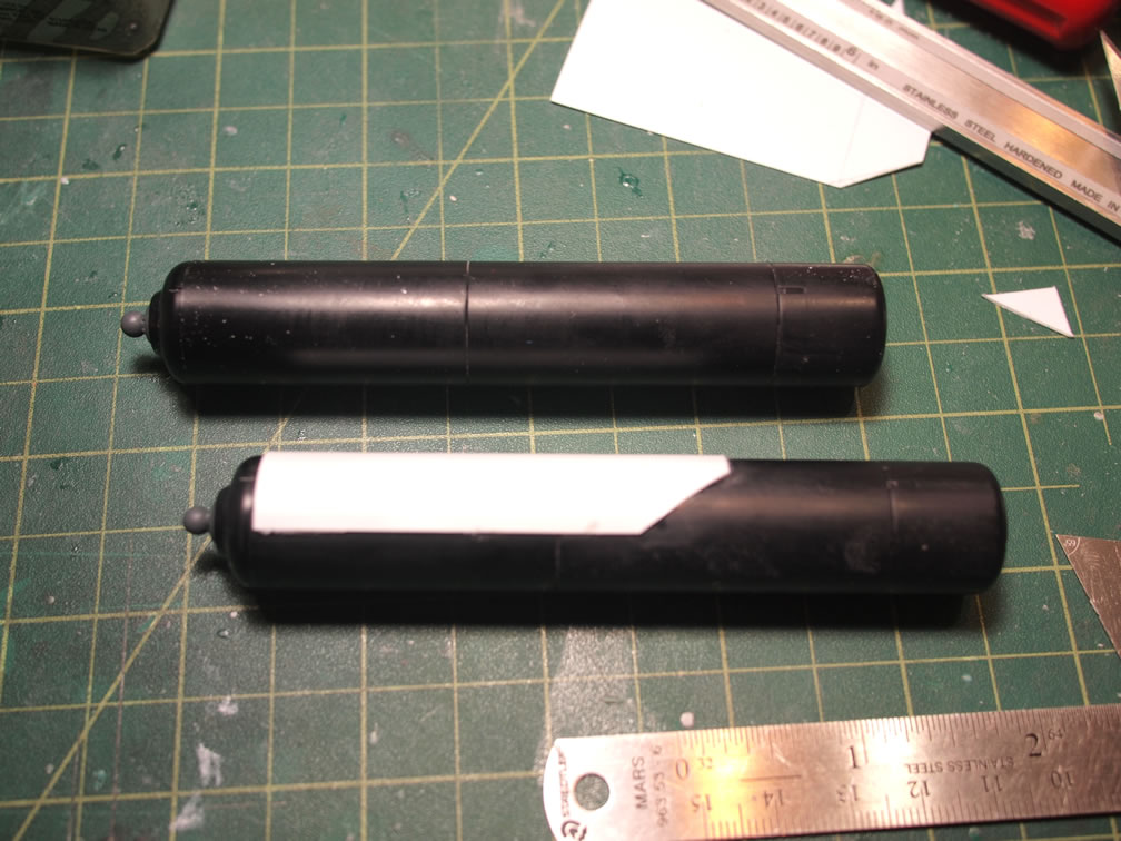
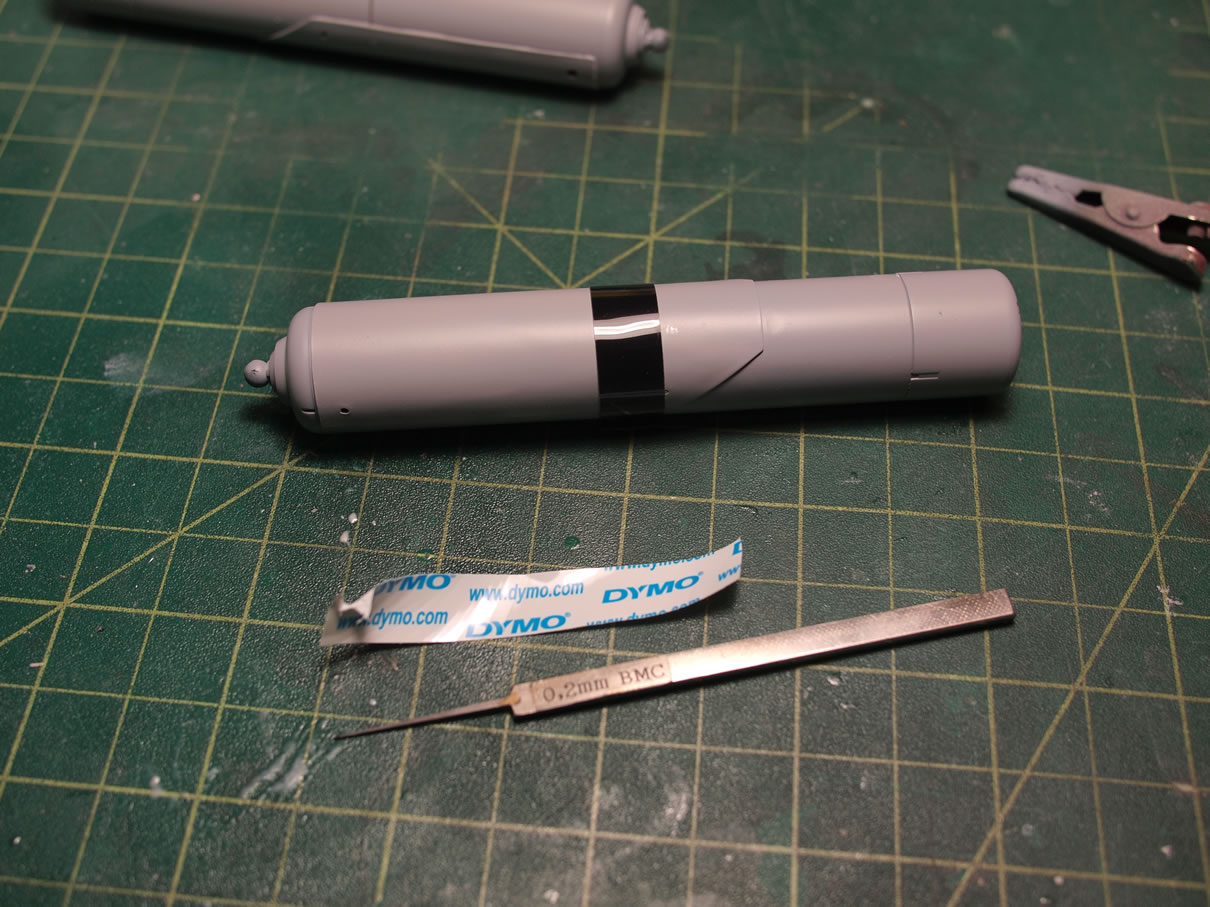
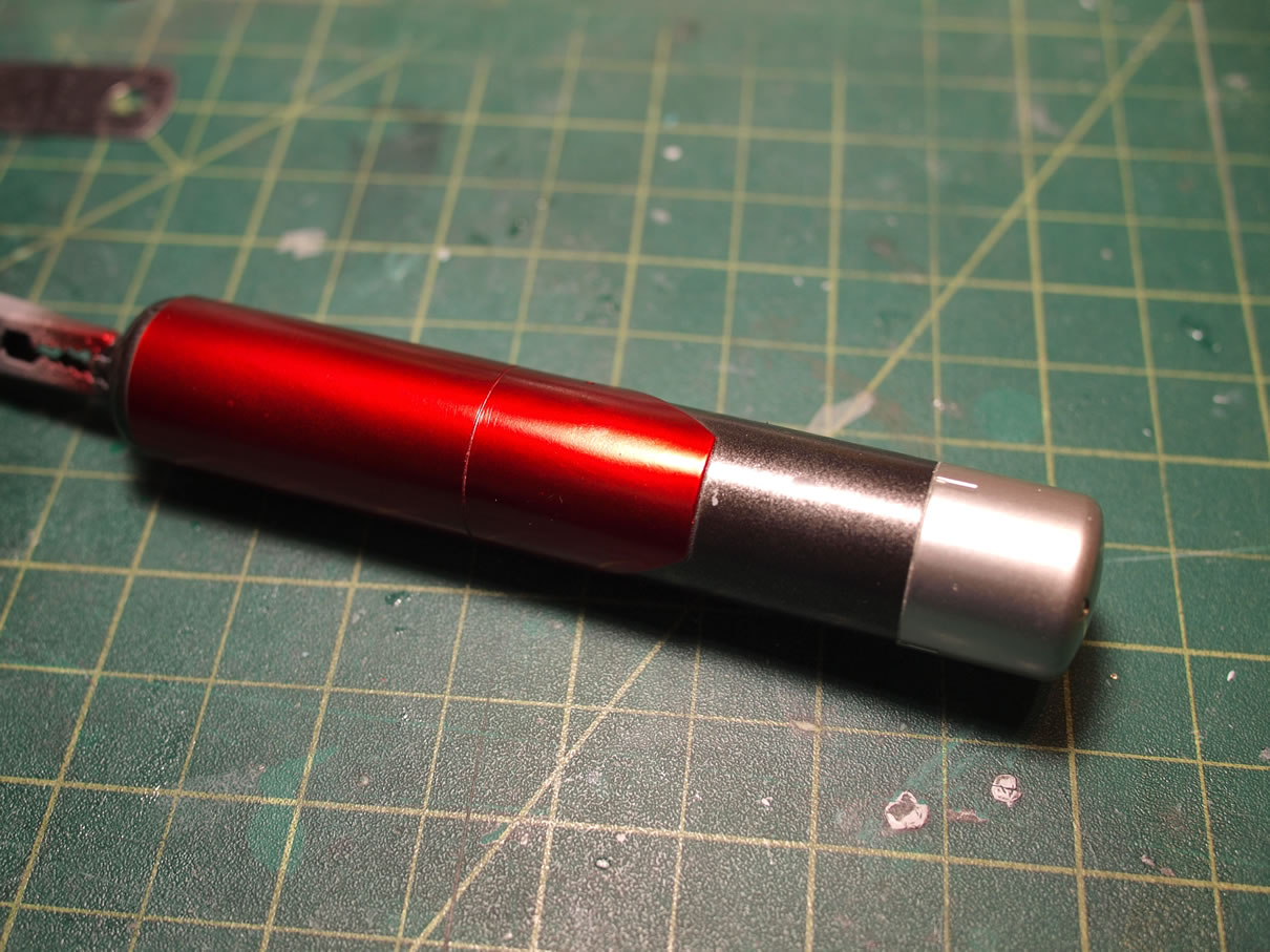
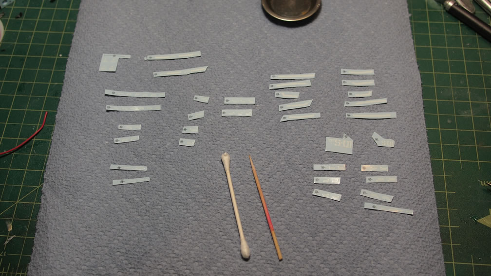
With the above said, I did do a quick little detail mod to the fuel tanks. Some sheet styrene is laid out and after some measurements were taken of the fuel tanks, a pencil and ruler are employed first, then the styrene is cut. A duplicate is made since there are two fuel tanks. The cut styrene sheet is then glued to the fuel tanks and painters tape is used to help keep the styrene attached to the fuel tanks while the glue welds the plastic plate to the plastic tube.
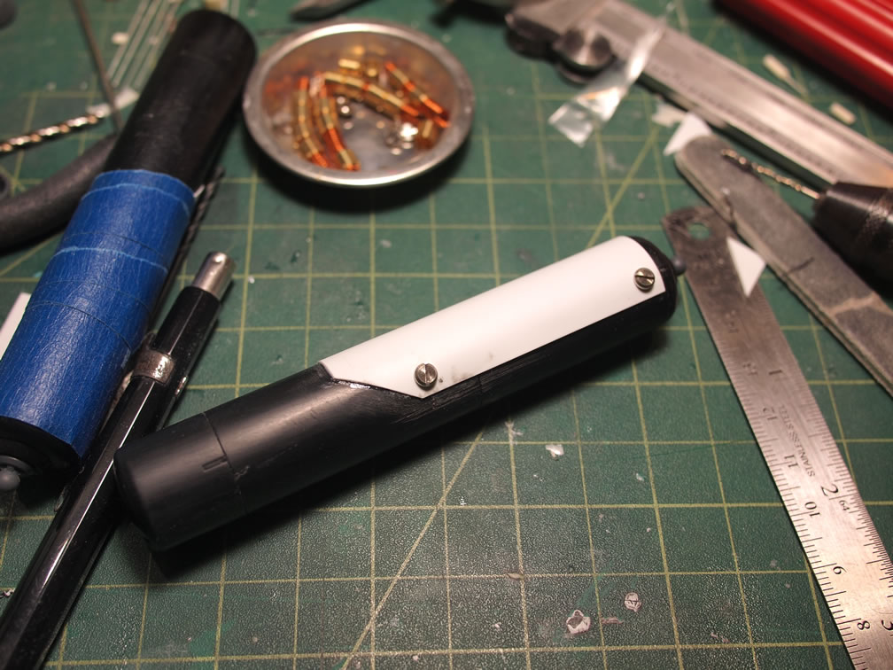
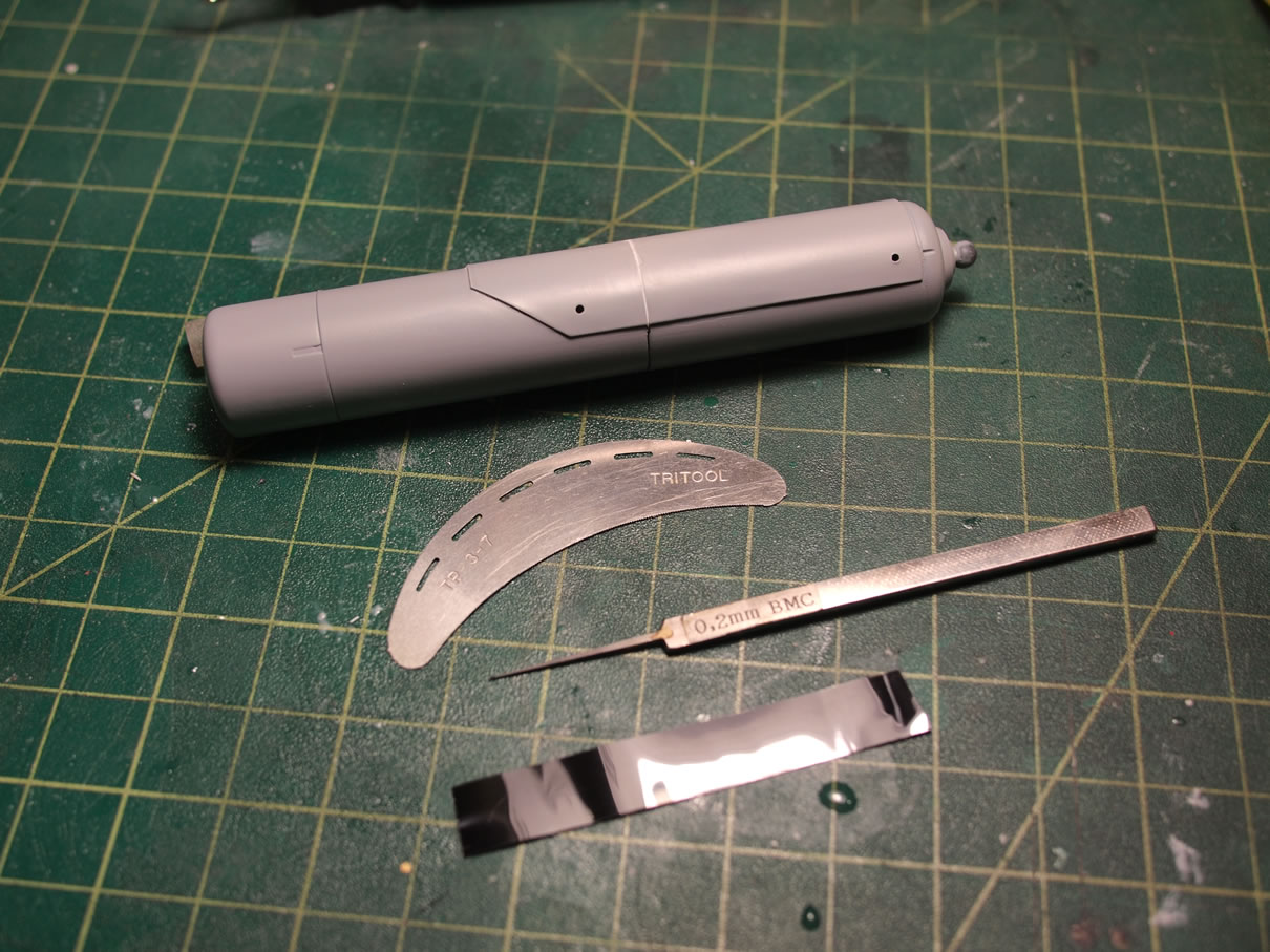
With the styrene detail in place, some holes are drilled for future placement of some metal minus mold details that should complete the quick detail modification. I still may add a panel line, but I want to see what the part looks like in a single color, so I’ll hold off on that decision until after I’ve primed the tanks.
February 10, 2014:
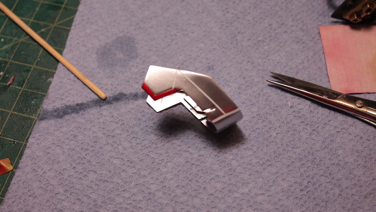
This week’s update finally gets some real painting for the Sazabi. The main body parts are got some primer and the base coat. And I actually finished one of the parts for the damn thing, the fuel tanks, complete with decals and final clear coats!
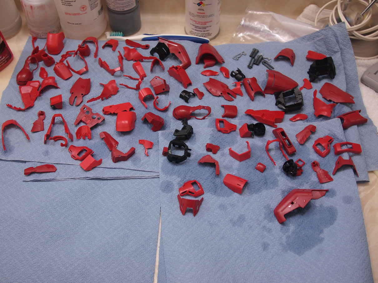
Before any paint can be sprayed, the parts must be cleaned. After all the sanding, cutting, and other building processes, I took the parts and basically washed them with an ultra sonic cleaner. Getting ready for some paint. I have found that during the building process; dust, oils from my fingers,fine plastic particles and a whole list of other random things have made their way onto the surface of the plastic. If I just took a can of duster gas and sprayed the parts removing a good number of the less clingy particles, there would still be oils and other things that are more sticky, not so easily removed by a puff of air. So into the ultrasonic cleaner they go, and with only water. The parts come out feeling clean. So they’re placed on some paper towels and left to dry.
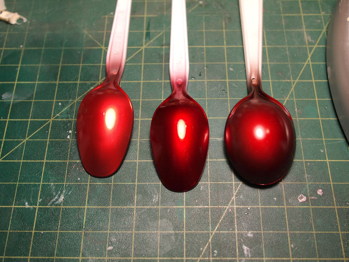
While the parts are dried, I took some time to run some color tests. I have several different clear reds and several different metallic paints. Various combinations produce different tones. I want to match up with the color scheme for the Ver Ka, with the three tones of red, the salmon, red, and deep red. Plastic spoons come in very handy for these tests as there are curves and it is a much more akin to what the paint will look like than spraying it on spruce, flat plastic, or even just paper.
After several tests, a few different paint mixes, and several hours later; I reached the three tones I want.
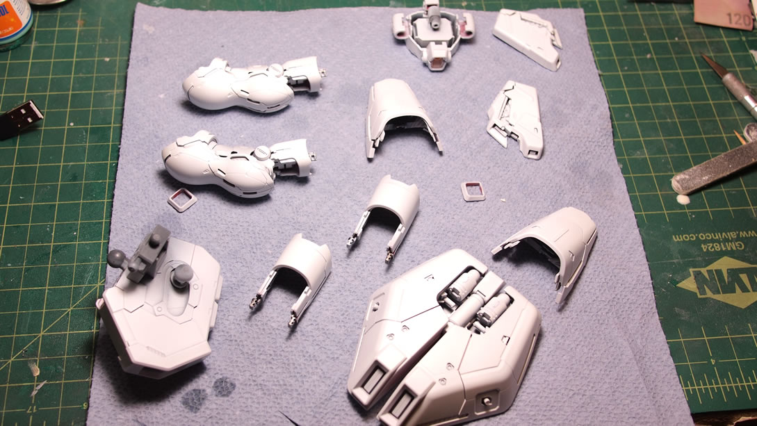
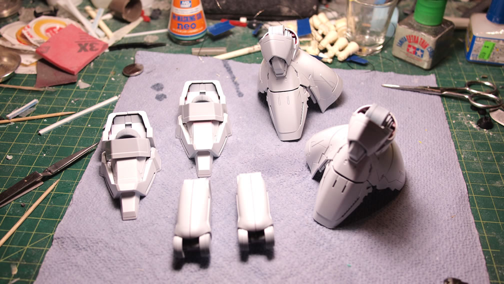
With the parts dry, I grabbed the inner frames and made sub-assemblies of all the parts. I’ve found that painting this way is less laborious as I can get several pieces painted at once, and keep paint tones the same on adjacent parts. Primer is sprayed and a few issues with missed sanding spots, rough sanding spots, missed nubs, and just issues with the surface prep from the mods; these select parts were re-sanded and then primed again. Some more than twice, but the end result is the following.
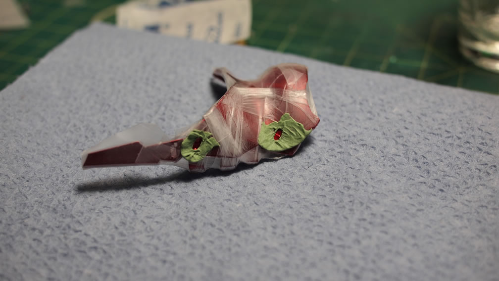
With the fuel tanks primed, the little plastic cosmetic mod looks like it belongs there as opposed to just being slapped onto the area. There’s a panel line that runs along the original tank, so I used some dynamo tape lined up with the original panel lines and scribe in some new lines along the added plastic. I used a scriber and some hasegawa metal saws.
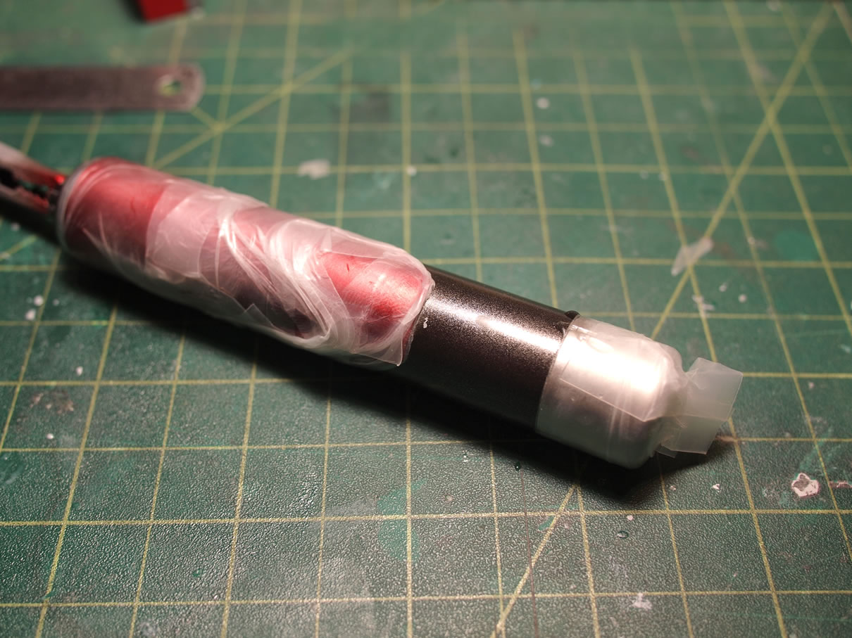
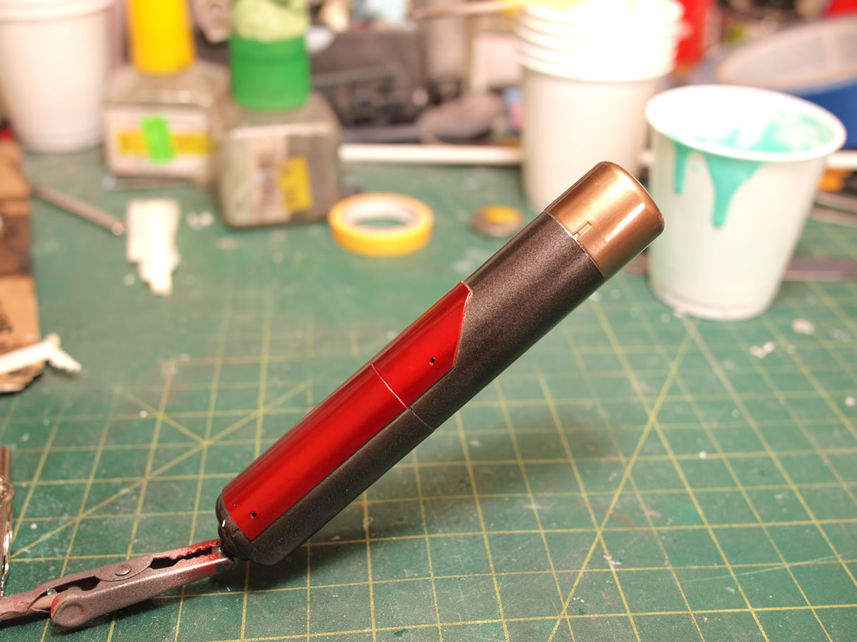
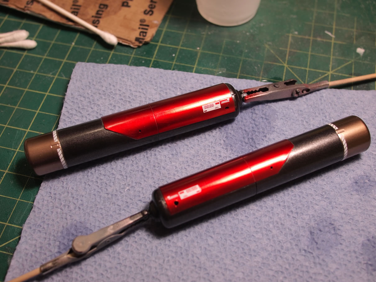
The main body of the fuel tanks were then painted with Mr Color Metal Black. This paint has some fairly larger metallic particles in comparison to alclad, but I like the effect. A few hours later with the metal black cured, the tanks were masked off leaving the plastic addition and the end cap. These areas were painted with Mr Color Super Metallic Titanium.
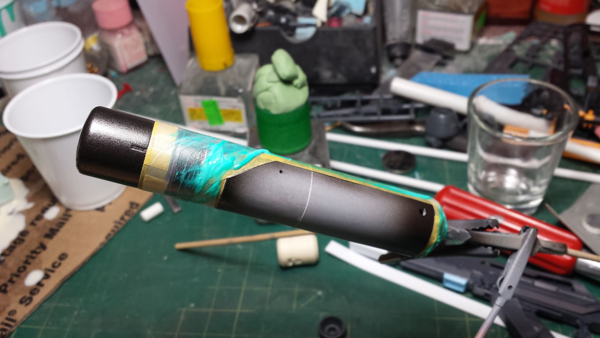
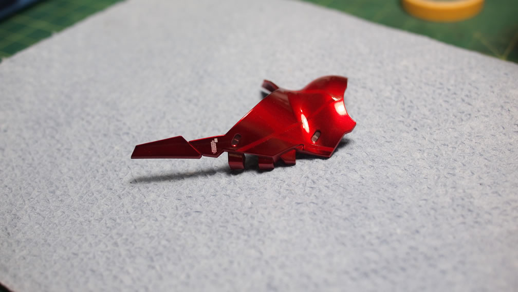
Another few hours go by and the end cap is masked off and Alclad Transparent Red is sprayed over the plastic add on part. After a few minutes of drying all the masking layers are removed and the little metallic minus molds are temporarily placed for a picture. Getting close, at least for one part.
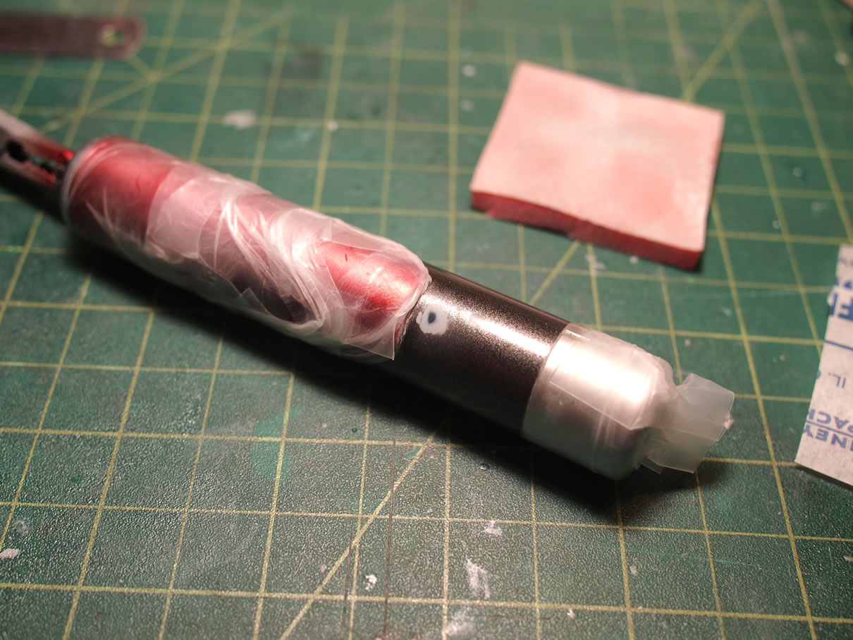
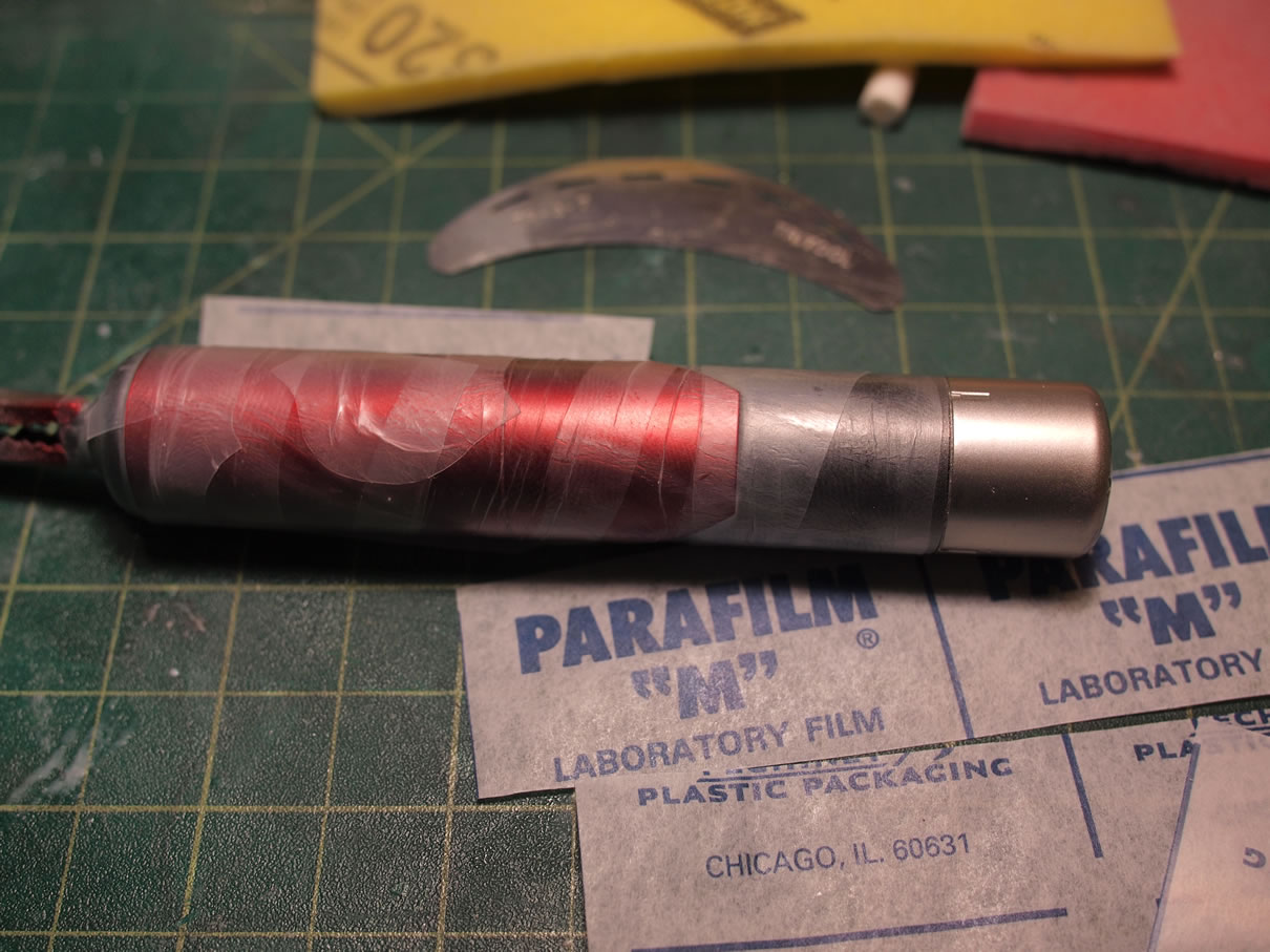
And when I said close for one part, we come to that part’s twin. While removing the tape, I also ended up removing a little chip of the Metal Black paint. This could have happened for a number of reasons. There could have been dust on the part and the paint didn’t completely stick. The primer layer below is visible so at the very least, it’s not the bare plastic surface prep that was at fault. Regardless, this needs to be fixed. The quick solution of just dabbing a small amount of paint with a brush will leave this even more visible. Simply masking the area off and just spraying isn’t a solution as the part is actually chipped and spraying paint over the area will show some crack lines around the chipped area.
So the proper way to fix this is to first mask off the areas painted in different colors. The plastic add on part is masked off with some parafilm and so is the end cap. The chipped area is then lightly sanded so the edges are blended into the surrounding areas. Then the part is repainted. Fixed without visible evidence there was ever a paint chip.
Things like this always happen. Knowing and accepting this fact of model building makes the occurance expected and much less frustrating when it does happen.
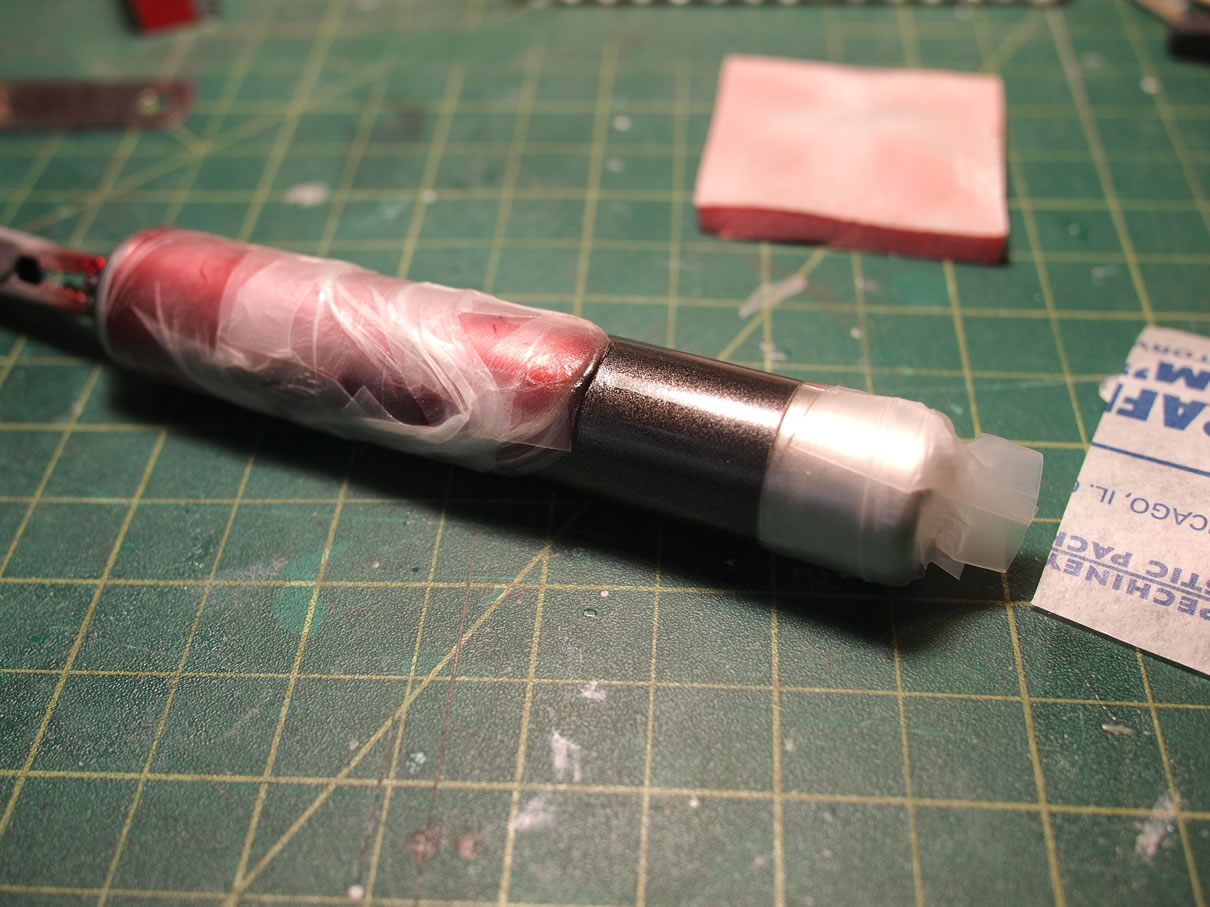
With the above area fixed, I was ready for the decals. Looking at the parts I felt that the titanium coloring was a little too light, and since the decals over that area are white, I wanted a more distinct tonal difference. So the whole tube was masked off again with parafilm and I sprayed alclad hot metal sepia over the end caps effectively darkening them.
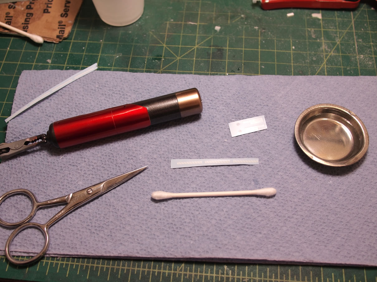
After everything is cured, I decided to get the decals done. Against my usual practice of spraying a clear gloss first, I skipped it and applied the decals directly over the bare paint surfaces. It is refreshing that Bandai is providing water slide decals as part of the kit instead of the dry transfers.
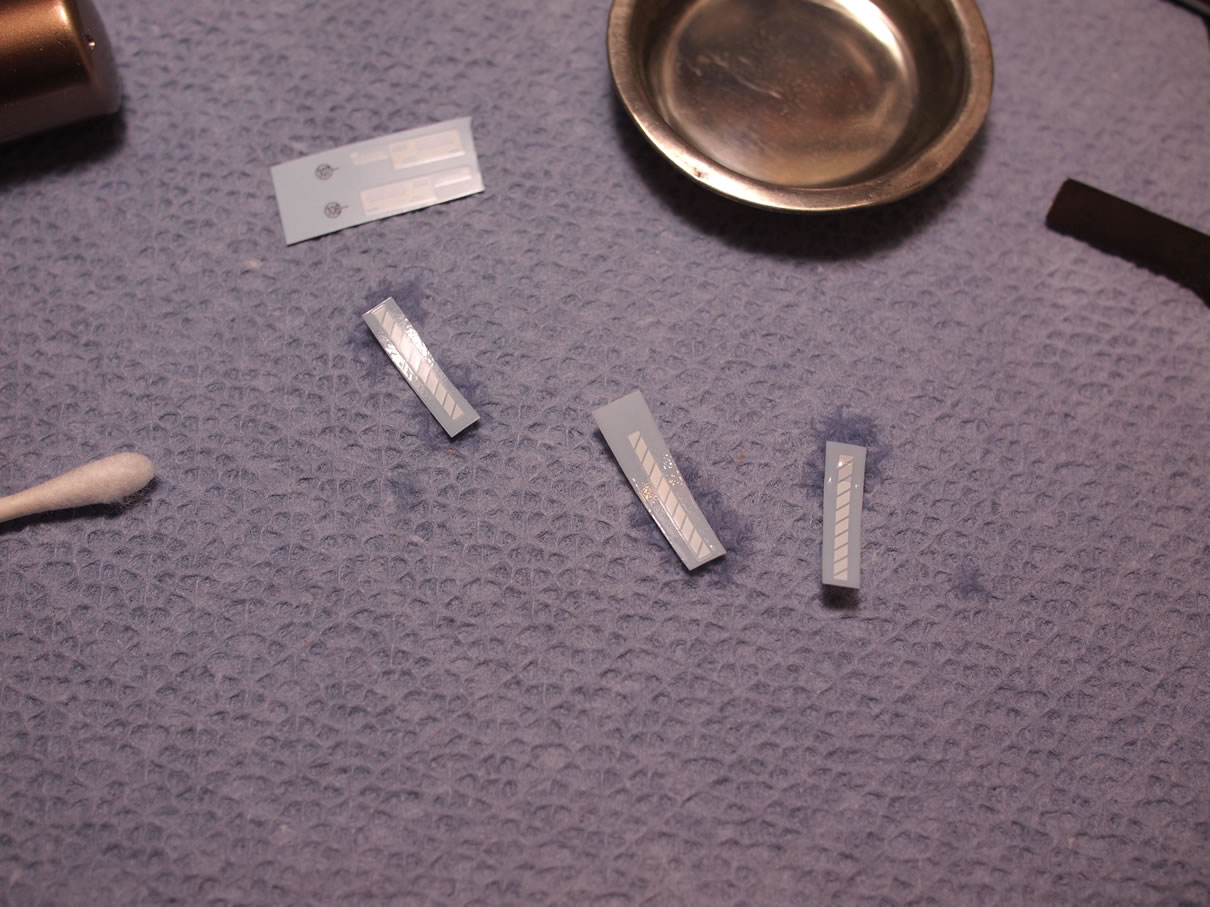
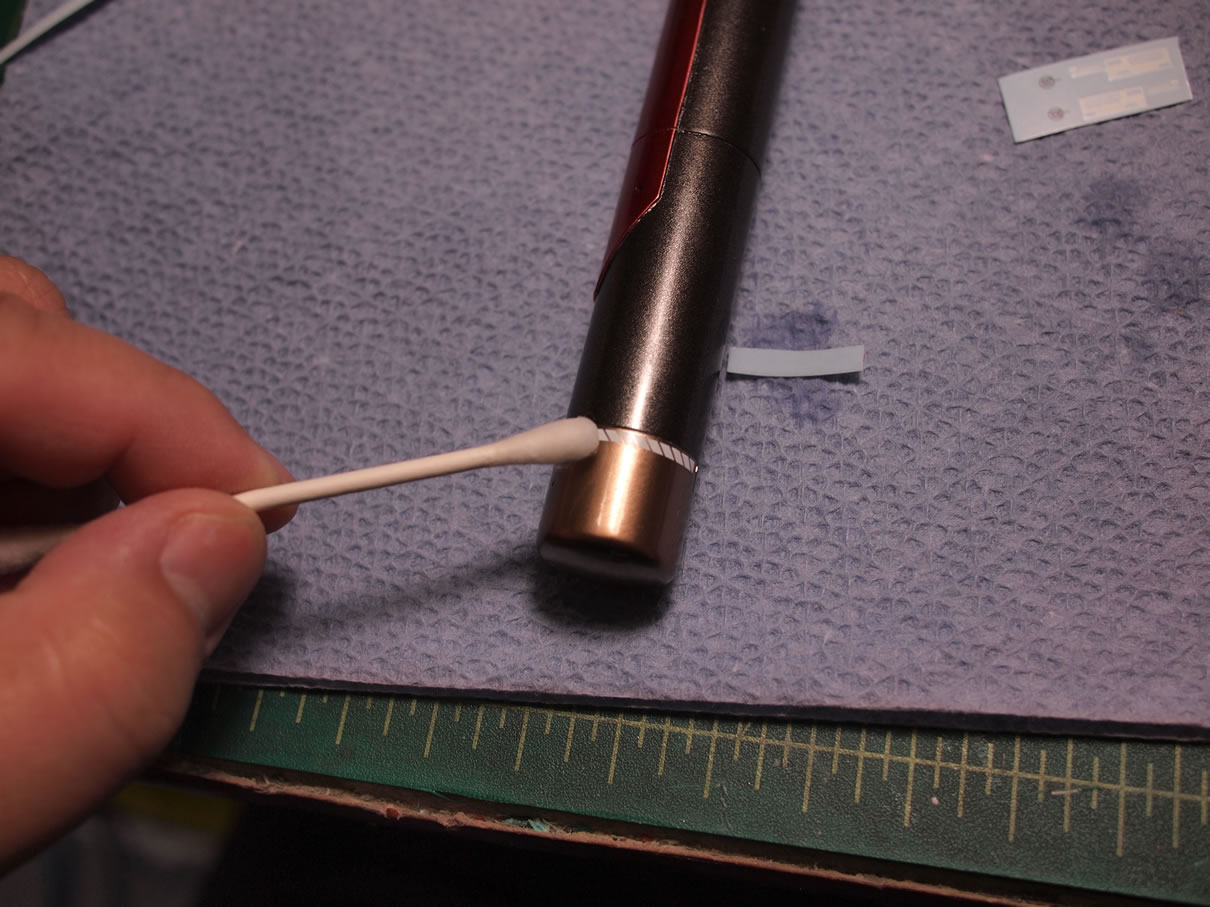
The decals are cut form the sheet and dipped into water for a few seconds and then removed and placed onto a paper towel. The couple of seconds in the water is already enough water to soak into the paper backing and loosen the decal. Soaking the decal in the water for too long will completely dissolve the water slide’s glue and the water slide will have difficulty sticking to the surface of the part without help from a decal setting solution. Since I didn’t soak the decals too long, I can rely on the decal’s glue and not worry about using a setting solution.
A q-tip and water help move and place the decals in the correct position and location. Once in place, a small paper towel piece is pressed against the decal and the part squeezing out any excess water. The part is left to sit and set up.
The candy red section is sprayed with a gloss clear coat. Once this dried for a few hours, this was masked off and a clear flat is sprayed over the rest of the body. I wanted the main body of the fuel tank to be flat finished with the detail part glossy. The metal minus mold pieces are now glued into position using epoxy glue to avoid any crazing or frosting that may come with using CA glue. I also like to avoid using styrene cement here as the uncontrolled melting may ruin the paint finish if I wasn’t careful enough.
So of all the parts, I can at least say that I’ve gotten the fuel tanks completed.
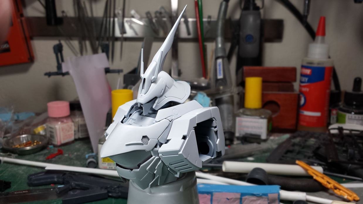
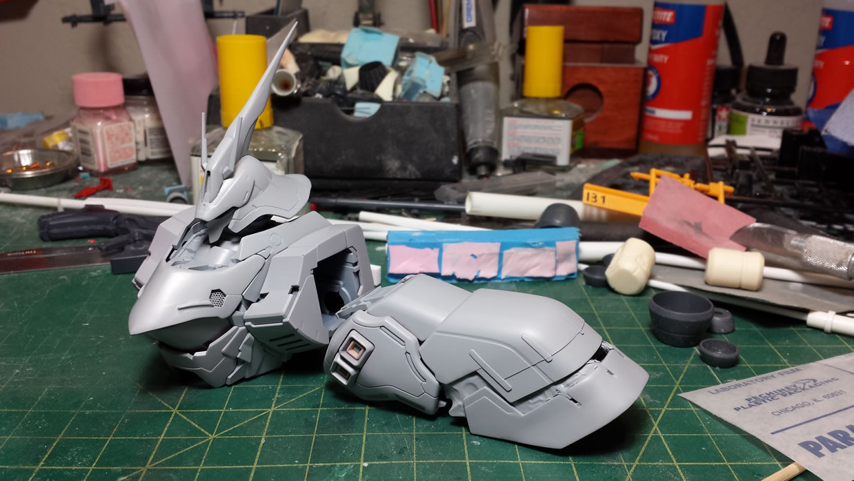
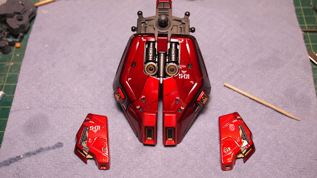
Back to the main armor parts here is a close up look at the main torso and head primed. All the mods should look seamless. Satisfied, the parts are then and base coated with Mr White Base.
February 17, 2014:
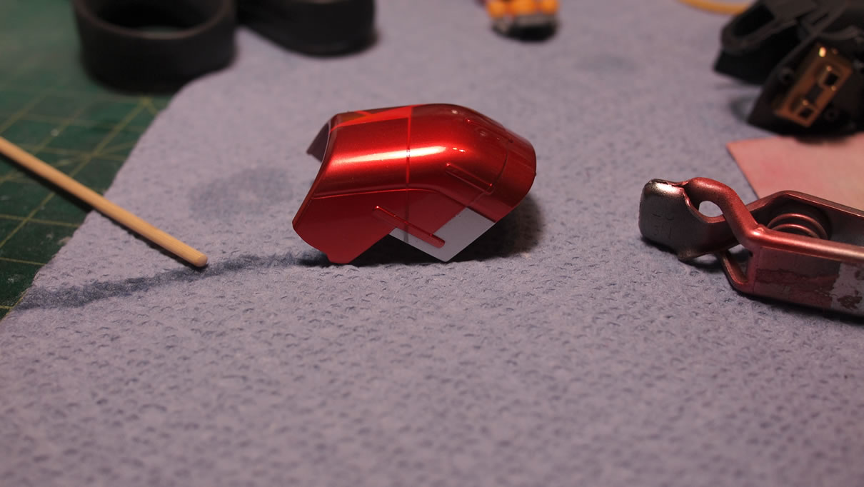
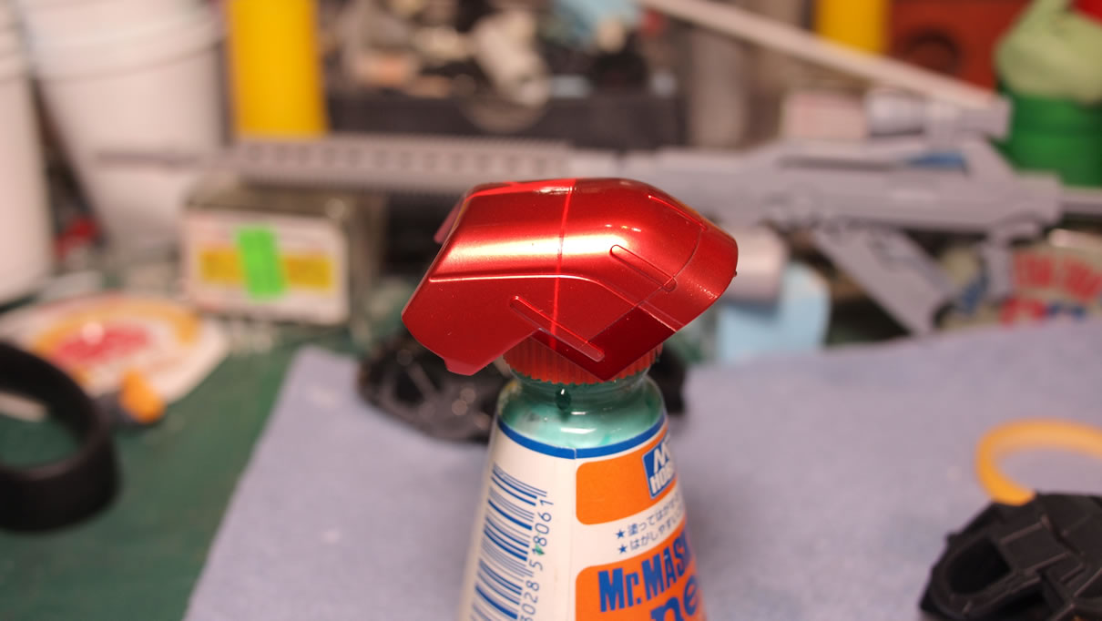
Since this is the actual body paint posting, I’m including a few pictures from the previous post so there is some better continuity. Weeks ago, I grabbed some plastic spoons to do paint tests. I used different base metallic paints and different clear reds from various brands before settling in on the three colors I have below. The process arduous, and I went through 10 different combinations before settling down. Below are the three colors to match up with the color scheme on the instructions. The lighter tone uses a mixture of clear pink, a small amount of clear orange, and clear red for tonal changes, sprayed over alclad super bright silver. The red is just Finisher’s clear red over alclad super bright silver. The deep red areas are finisher’s clear red over alclad polished brass.
Also in this post, 3D printing!
Again, I’ve found it fairly important to wash the parts before any paints are sprayed, including primer. But once dry, the parts are primed.
The parts were placed in sub assemblies then primed. The kit has so many parts, its irrational to paint all the parts separately. So simplicity and ease, the parts are primed and predominately painted in sub assemblies. The base white coat is also base coated as sub assemblies.
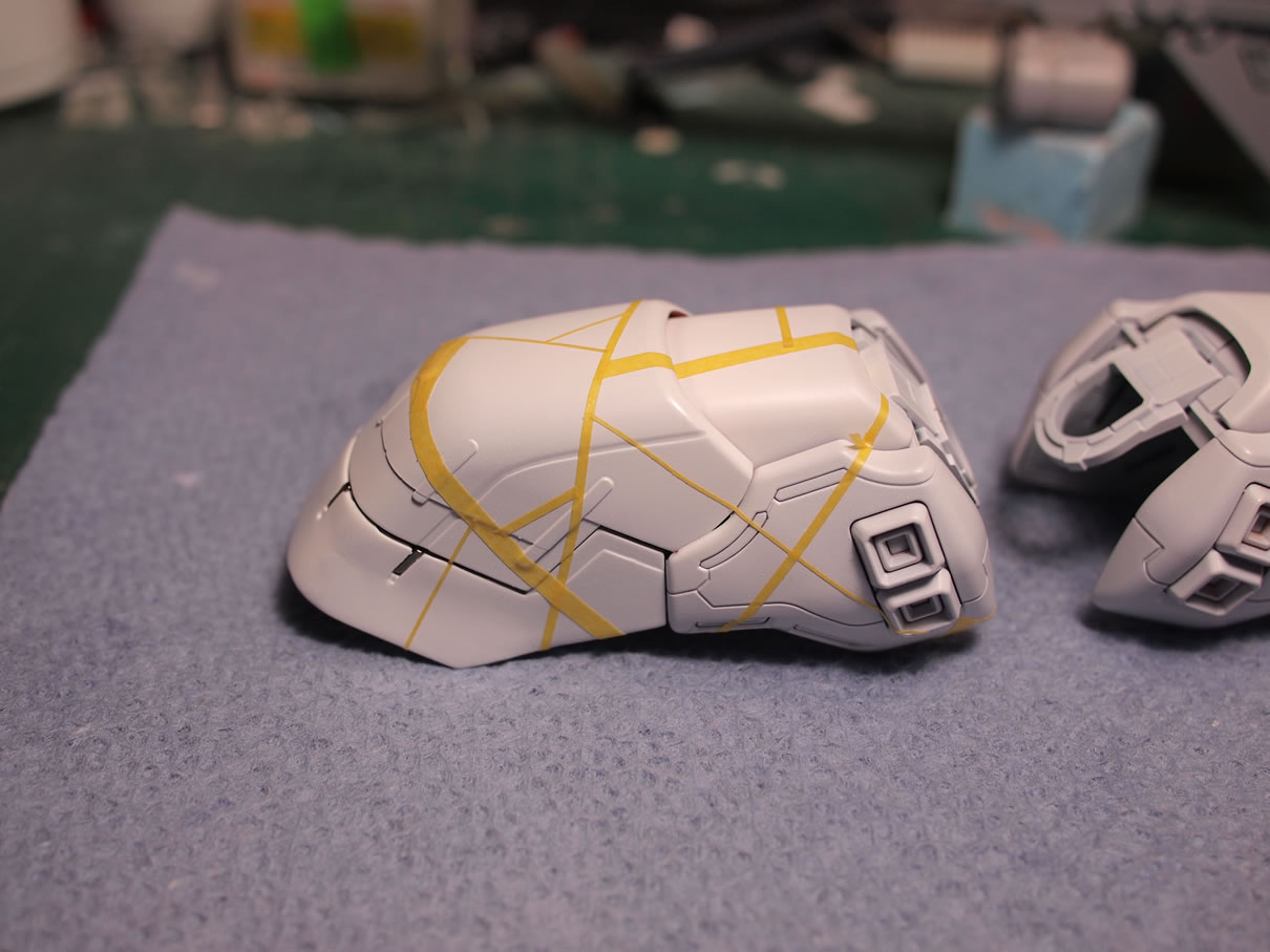
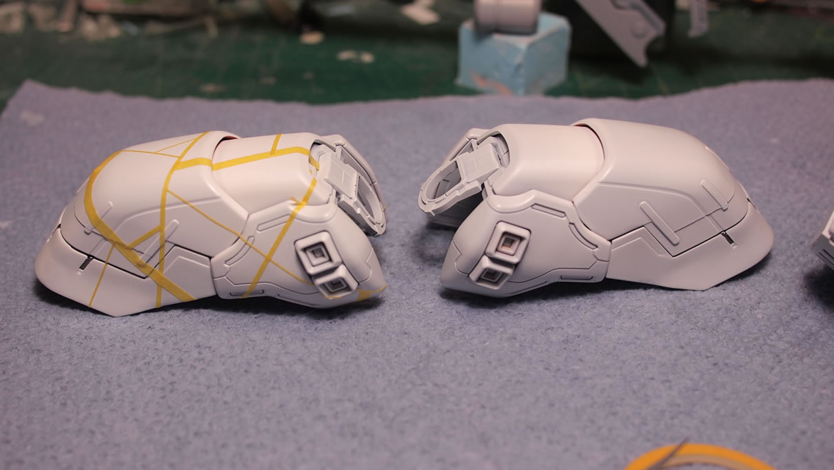
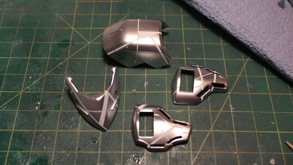
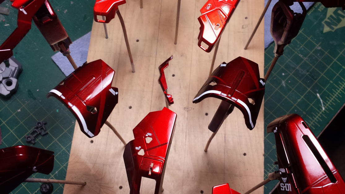
The paint scheme I want requires a little bit of masking using different widths of masking tape. Here I have a .7 mm, .4 mm, and 2 mm width masking tape rolls. The sub assemblies are masked off with a random line pattern then the tape is cut between each part section. The parts are then separated into atomic units to finish the masking lines and then they’re ready for paint. This is the first masking session.
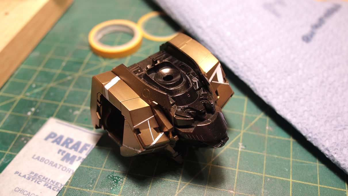
After masking, the parts that will be in deep red are now base coated with black.
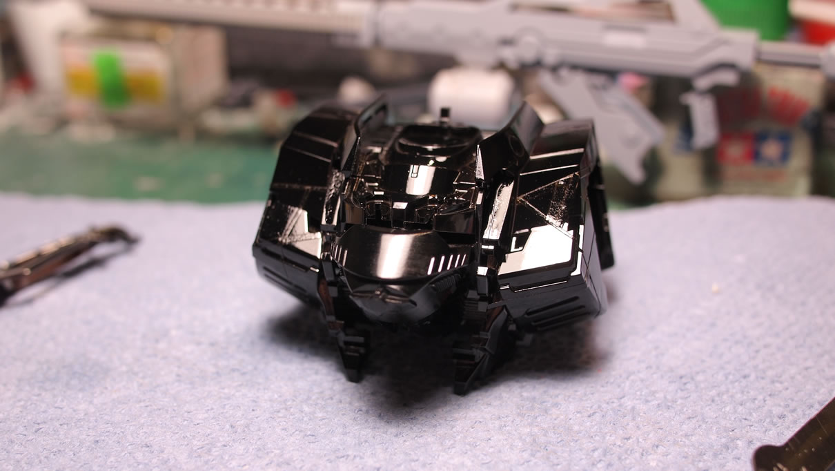
The rest of the parts are painted with Alclad super bright silver. Once the black pieces are cured, alclad polished brass sprayed. When the paint is dry, the masking layer is removed. Some care is needed so that paint doesn’t get lifted. If the parts were washed and clean, the removal process should be fairly clean. In cases where only the previous layer of paint comes of and the primer is still on the part, then the paint over the primer wasn’t given enough time to cure before the masking process begins. Now if the primer and paint layers come off, then the issue is that the surface wasn’t clean enough or the primer wasn’t given enough time to cure and bond to the plastic. And sometimes will bond to the paint layers sprayed over the primer instead. So proper cure times are important.
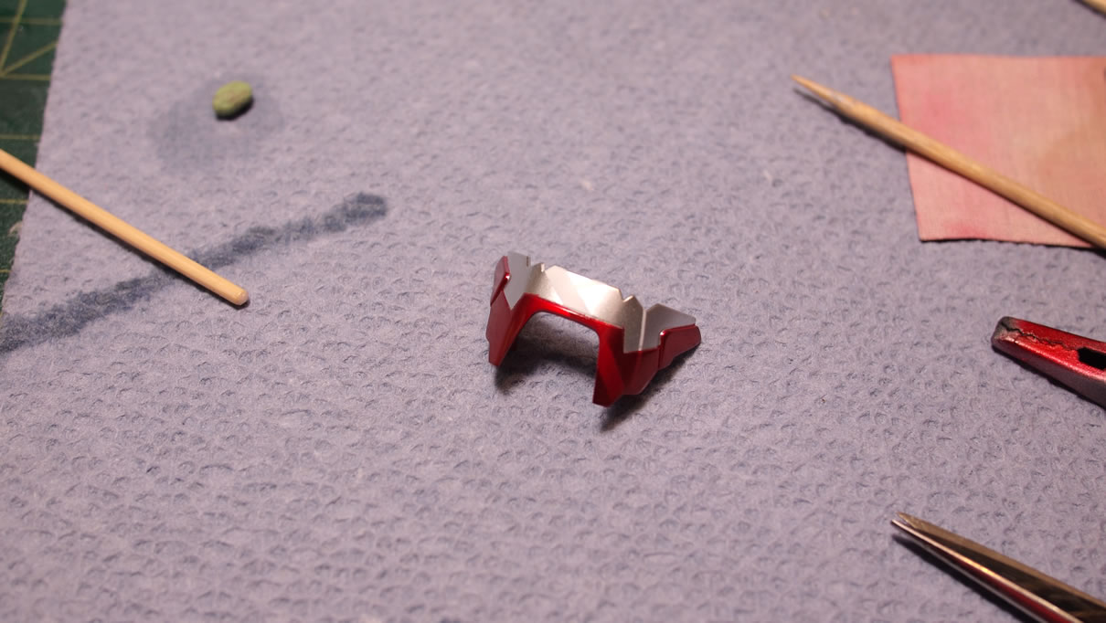
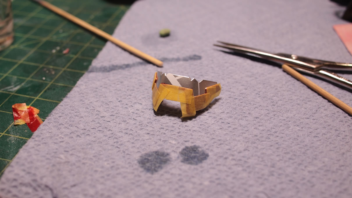
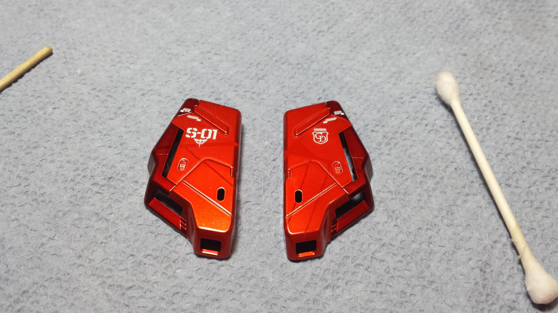
With the parts ready for paint, there are a few pieces that are dual colors. The kit comes with some stickers for these parts. So since I’m not going that route, these parts are masked off first. The the parts are painted with the appropriate clear tone. Once this cures for a full day, the masking is removed and the previously painted areas are masked off. It is a painfully laborious task, but the results are worth the effort.
All the parts are still in the atomic pieces, so once the paint cures, I went and did the decals for all the parts. About 6 hours after the decal application, the parts are sprayed with clear gloss. Waiting the minimum of 12 hours after the clear gloss application, I went and started to assemble the parts back into their sub assemblies. During the assembly, I did accidentally chip some paint and for that reason, the right shoulder part is incomplete. I have sanded down the chipped areas and repainted and clear coated. It is absolutely to allow the parts to cure at their own rate., Rushing always results in mistakes.
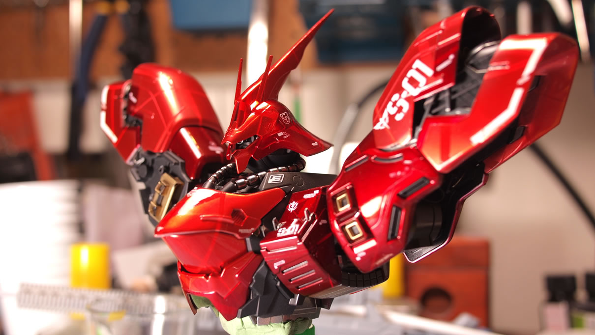
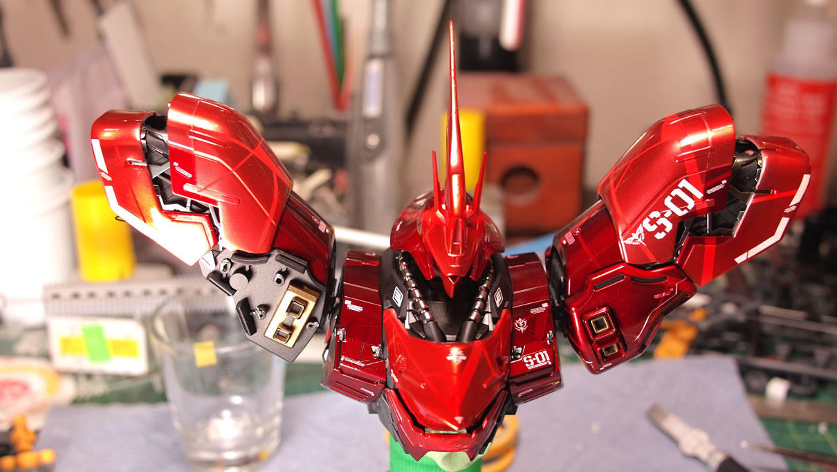
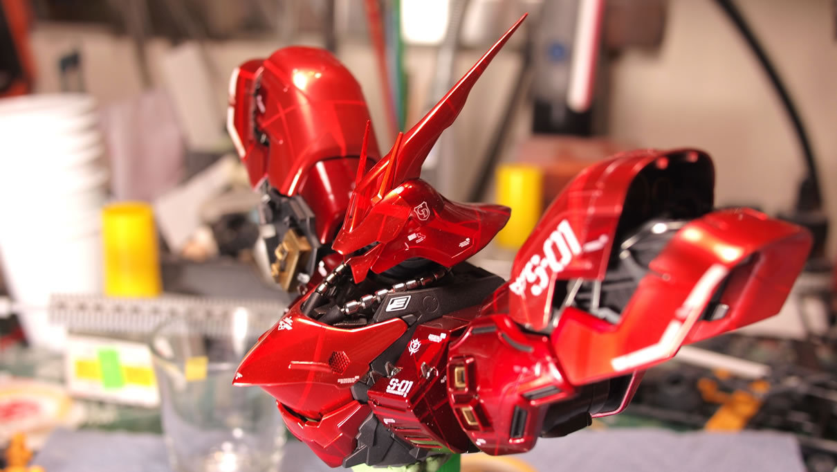
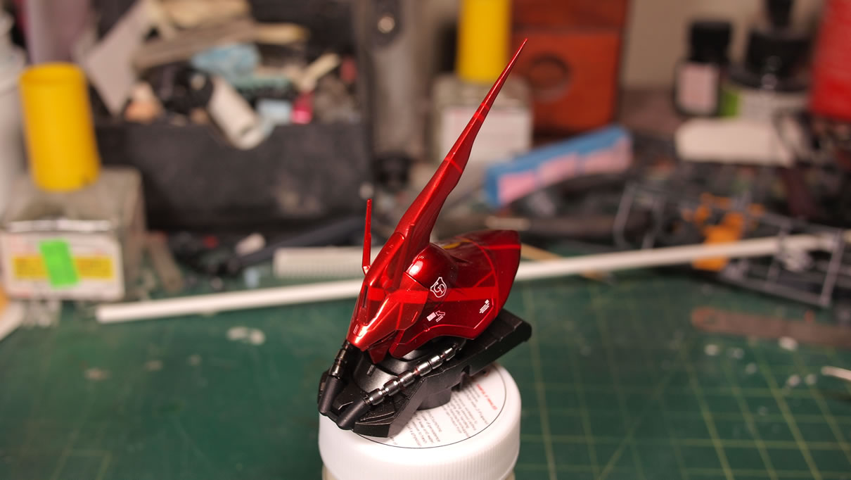
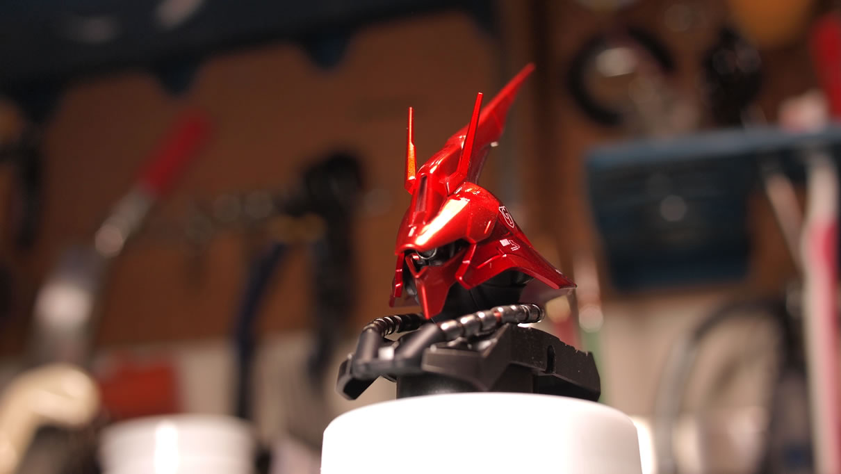
Here is a close up for the Saz’s head. Looking closely, you can almost see the mono eye mod.
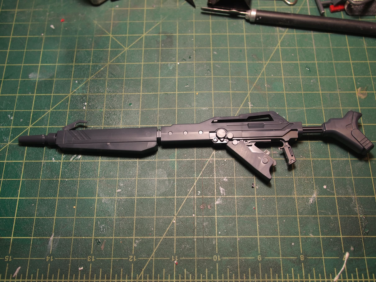
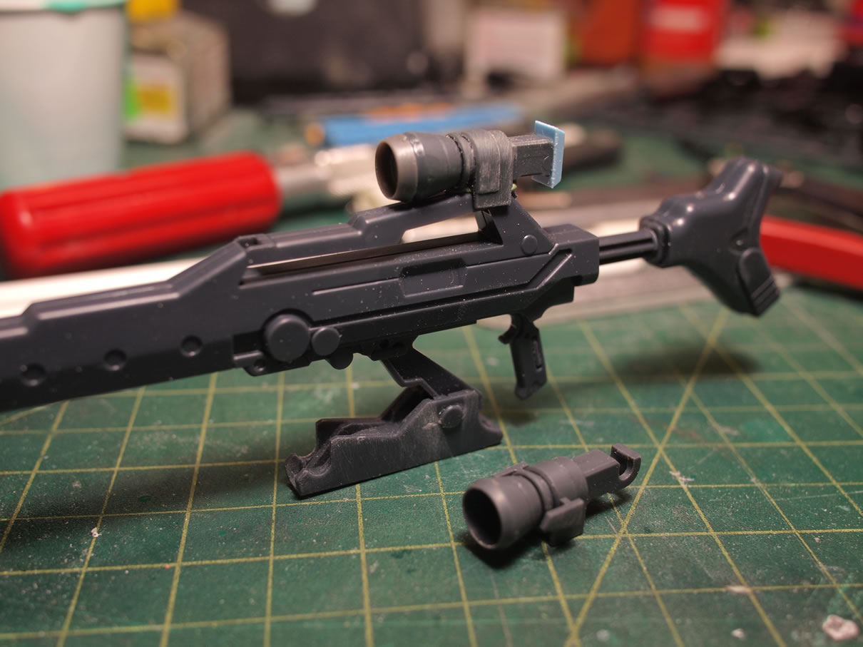
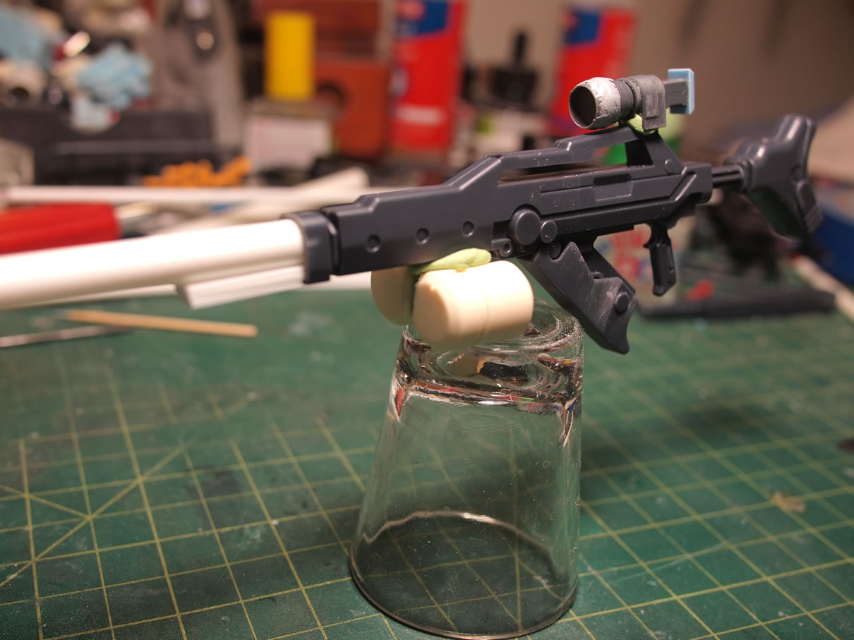
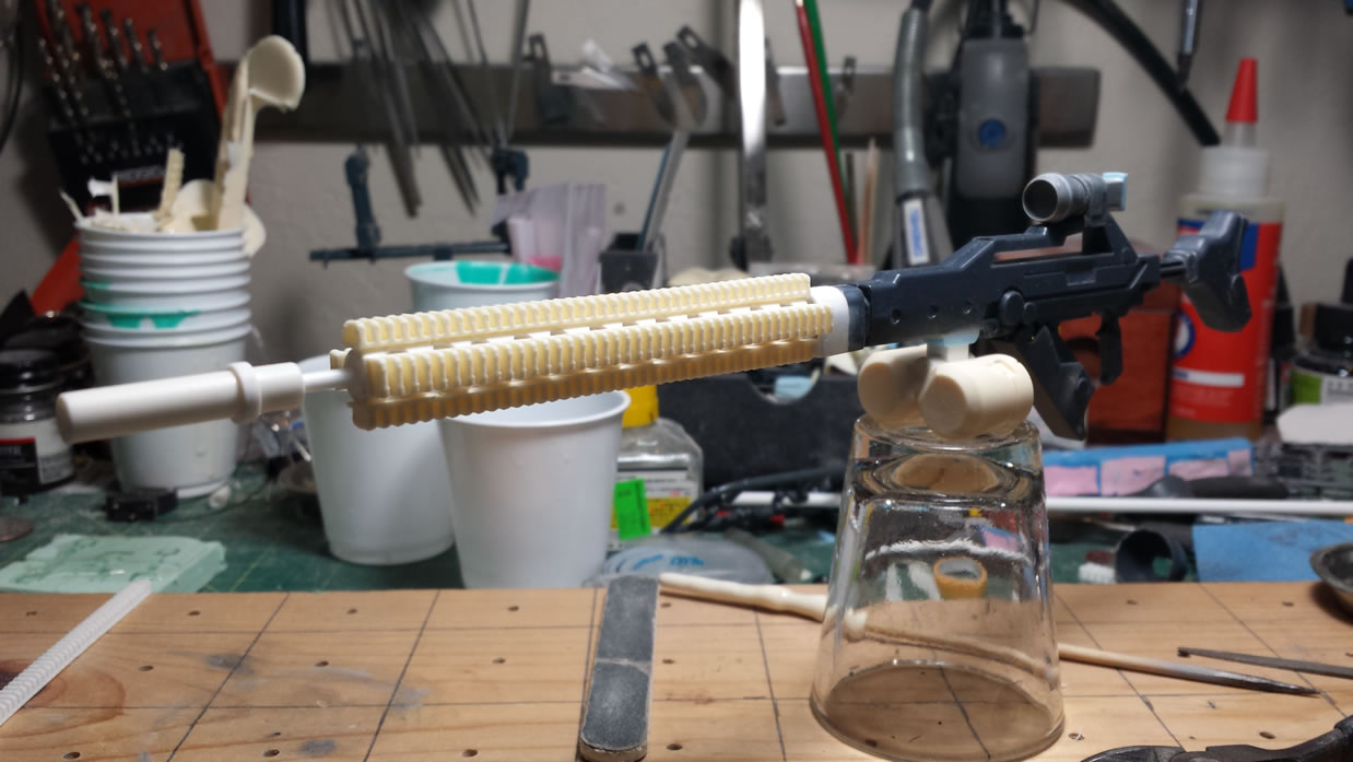
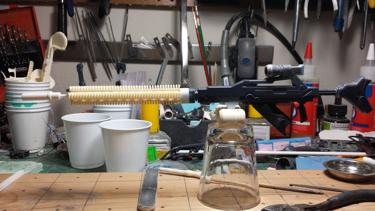
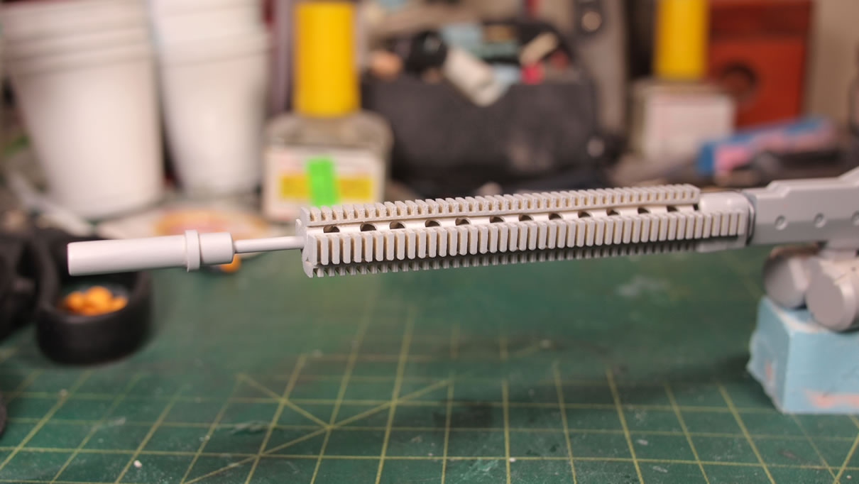
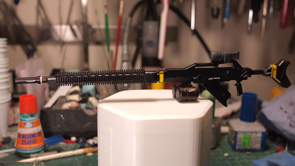
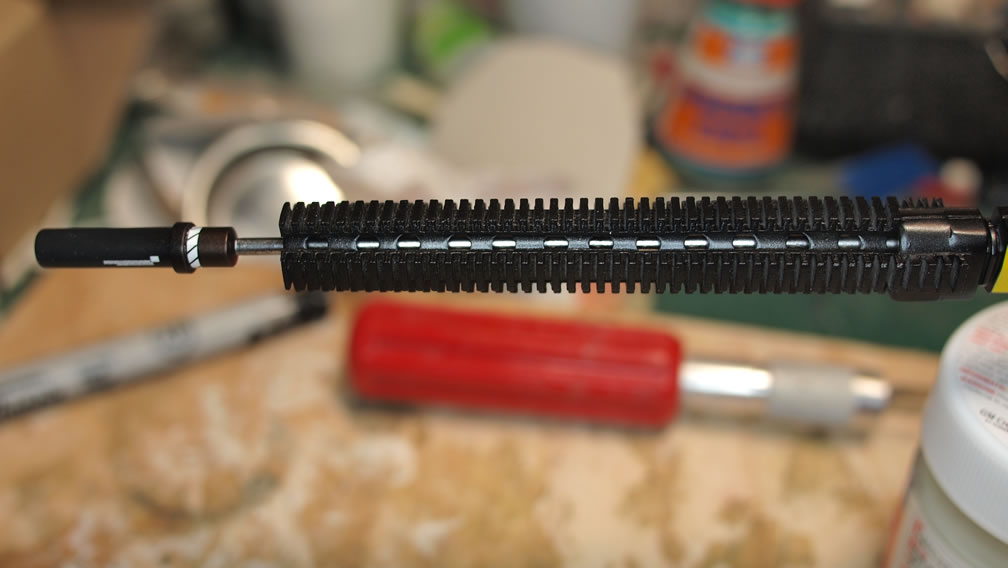
Next up is a build process that has also been progressing along in the background. Sazabi long rifle modifications. The rifle is snapped together and a picture is taken in it’s untouched glory. First things first, the hobby saw is brought out and front end is cut.
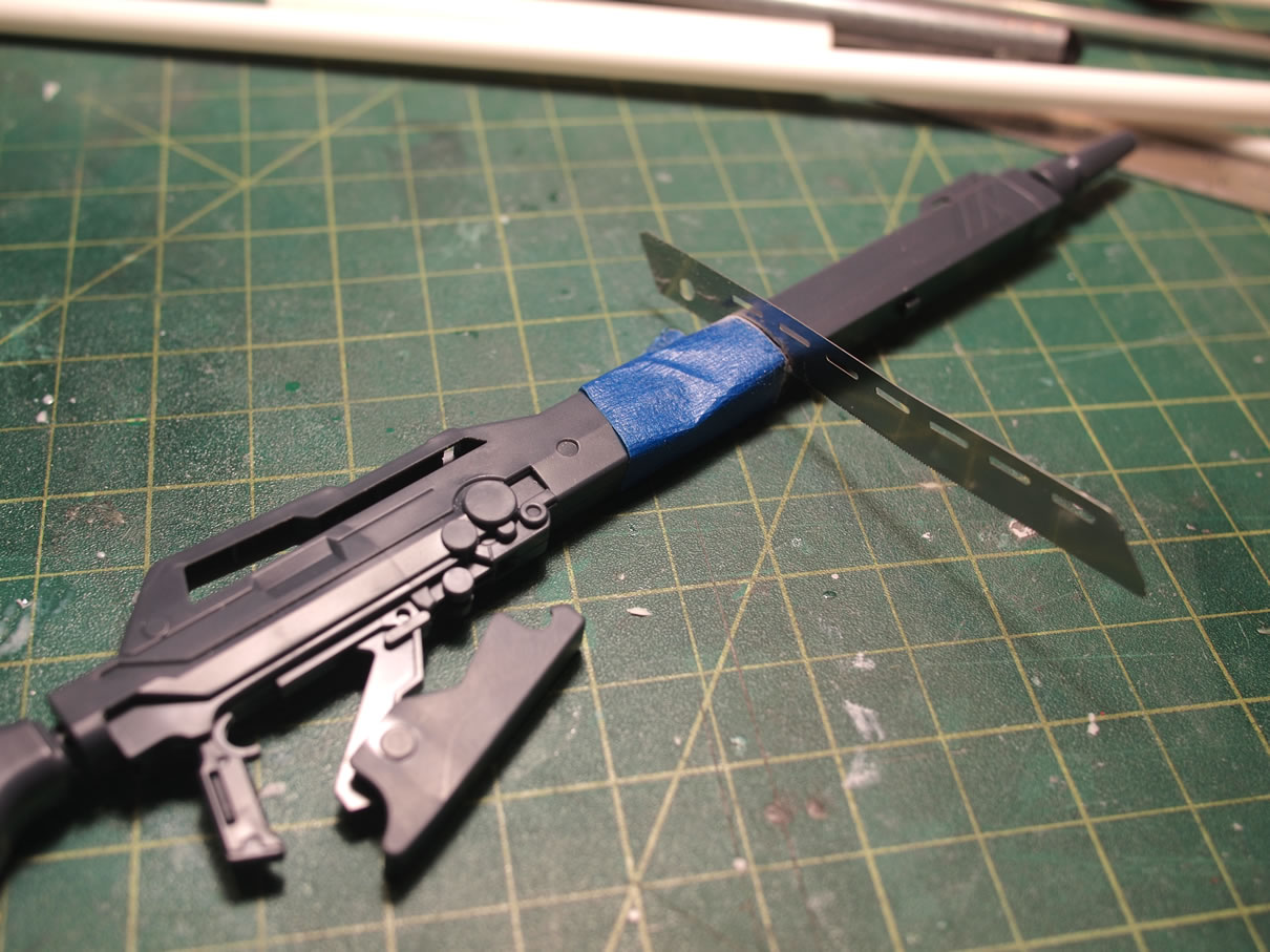
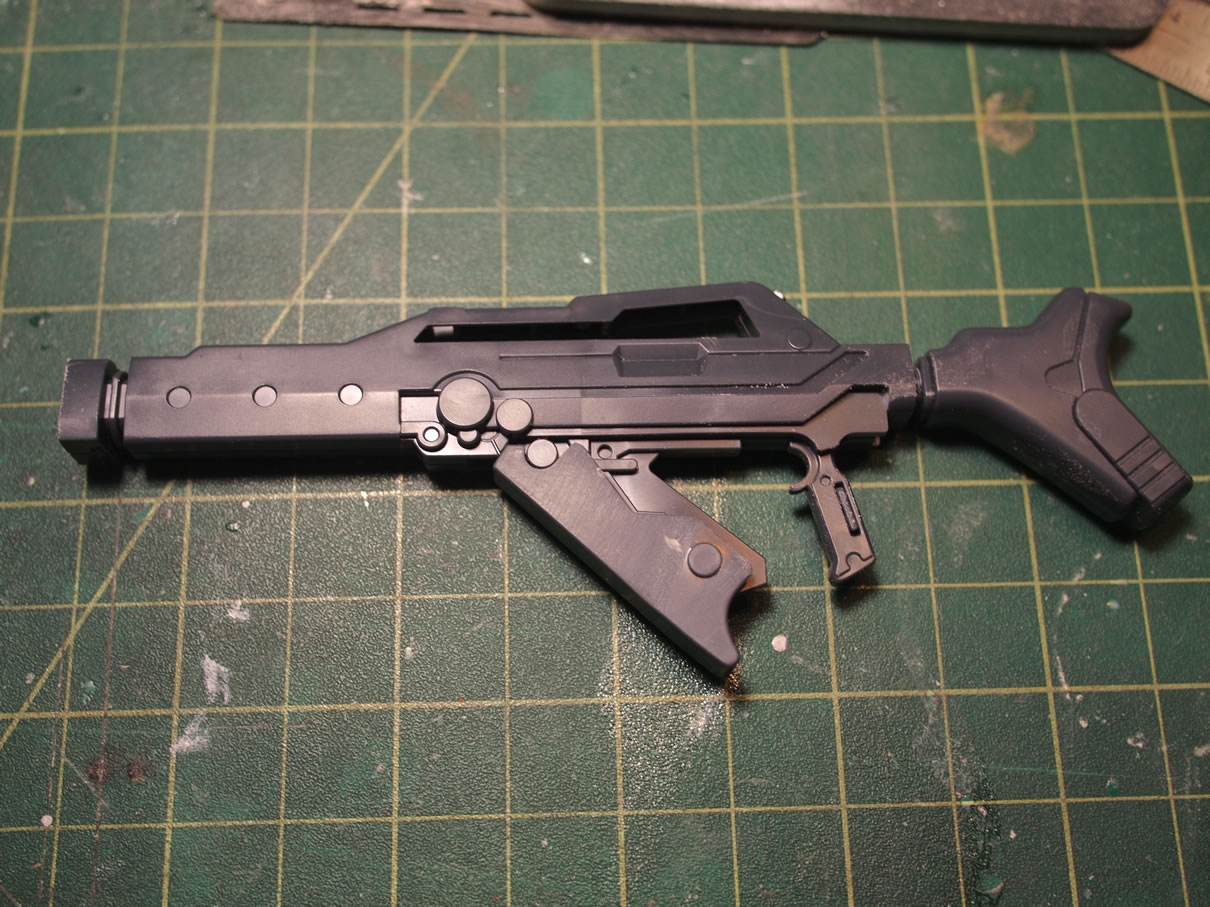
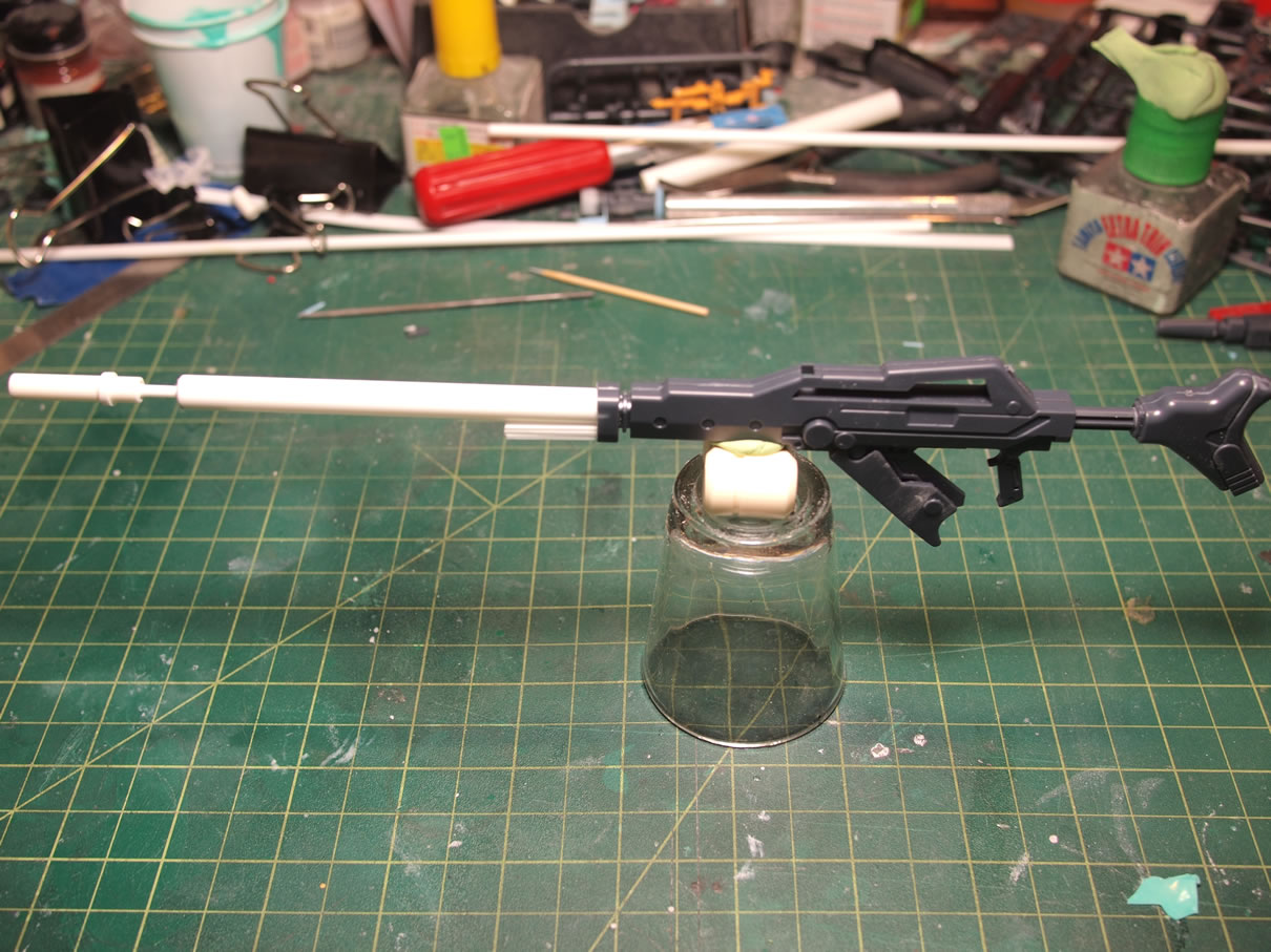
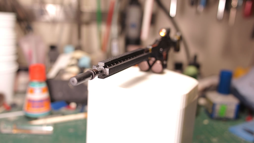
With the front end gone, I can now use some styrene tubes of various sizes and create a new outer and new inner barrels. The inner barrel is centered using consecutively smaller styrene tubes glued together. The silencer is built in the same manner.
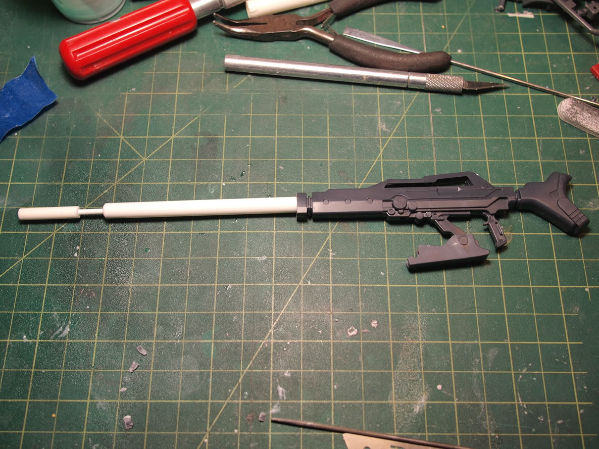
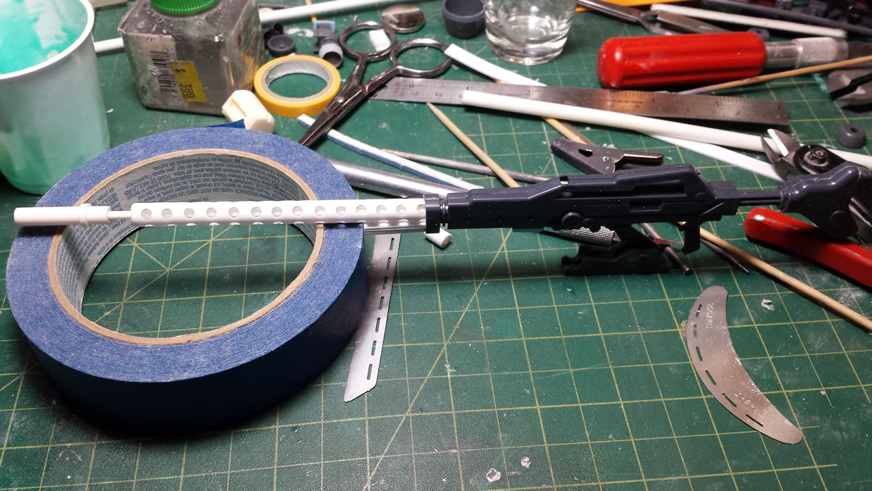
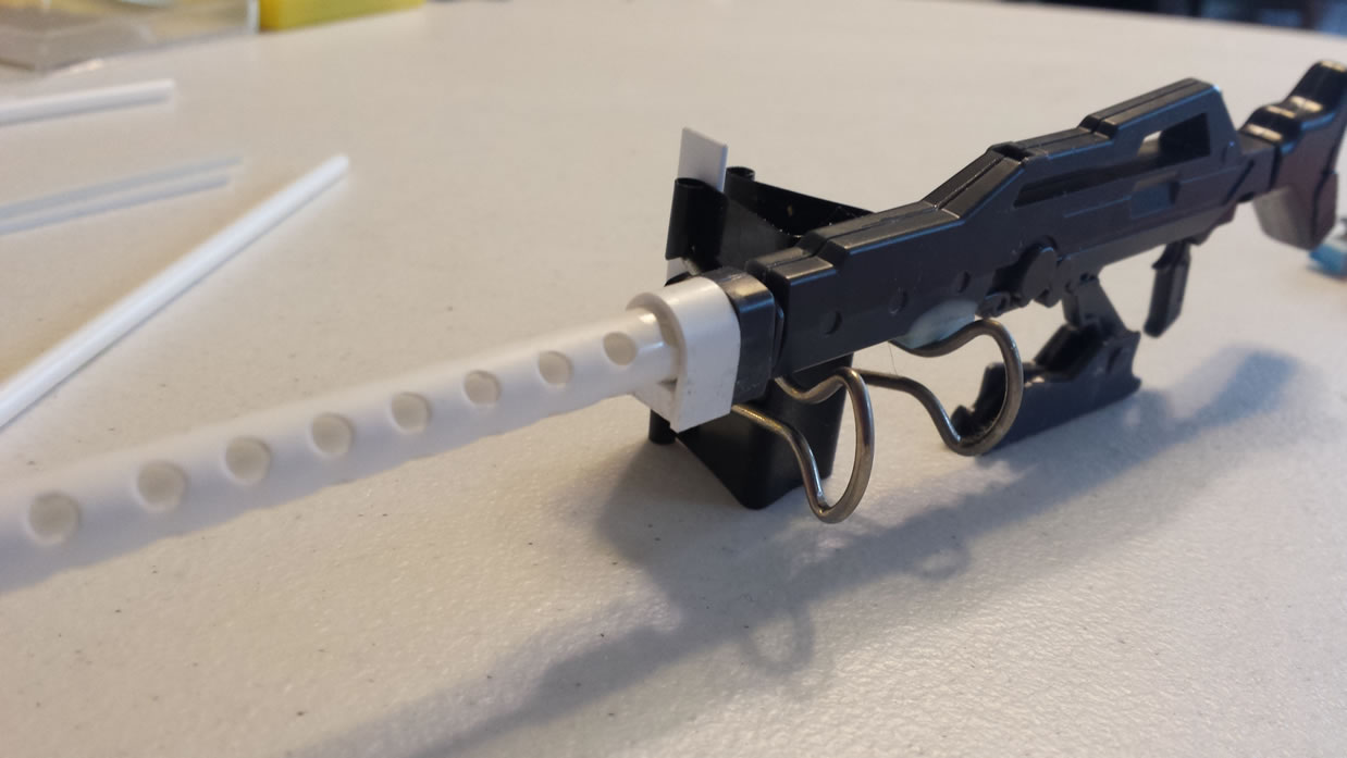
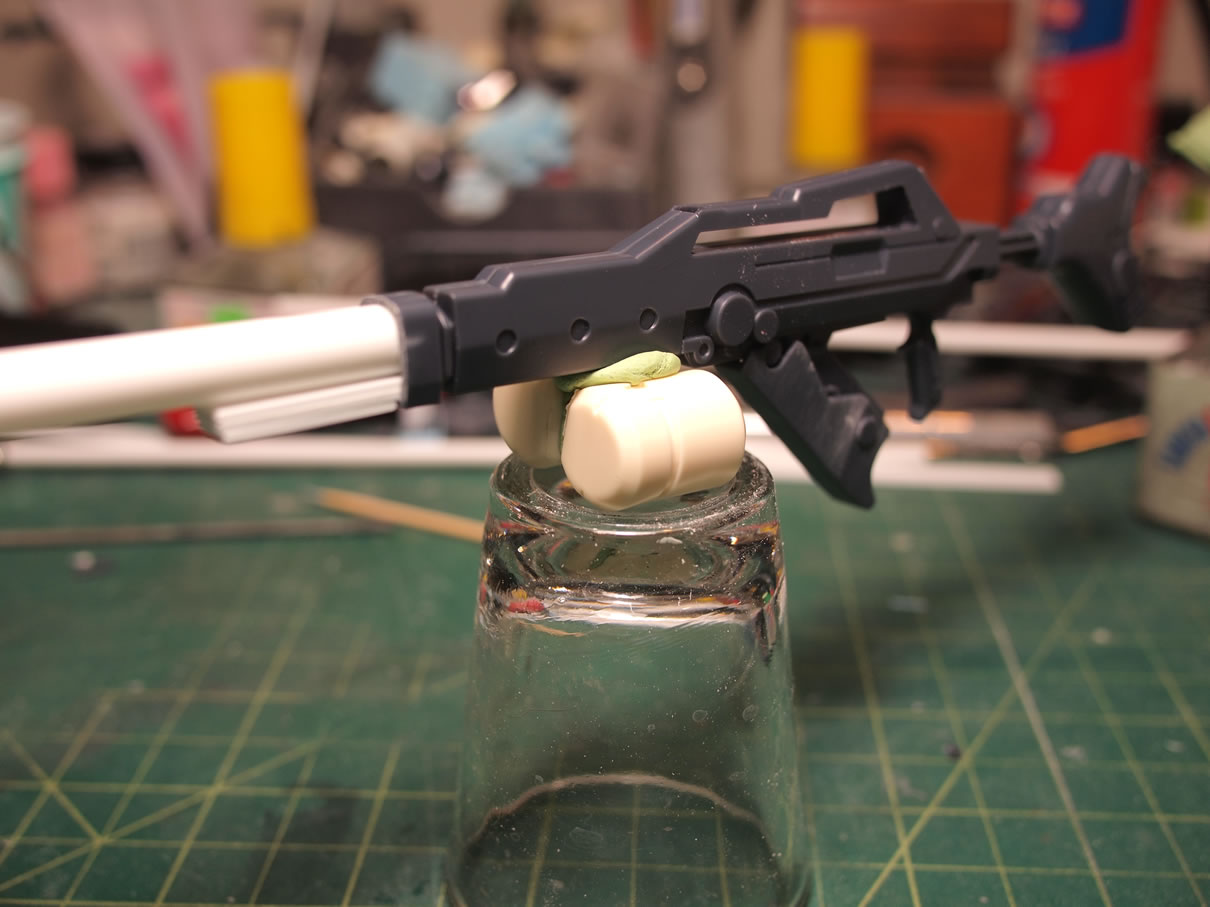
The outer barrel is vised up and measured. Using a drill press, holes are drilled straight through the barrel at each marked off area. The outer barrel is then glued to the rifle’s front end. Some styrene is stacked and glued together as filler between the barrel and the bottom of the rifle. Another piece of styrene is bent around the barrel and glued into place against the roughly cut front end of the rifle for use as a transition piece.
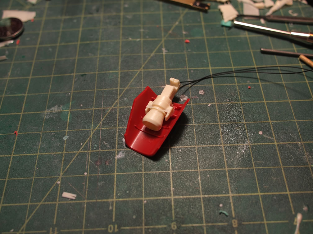
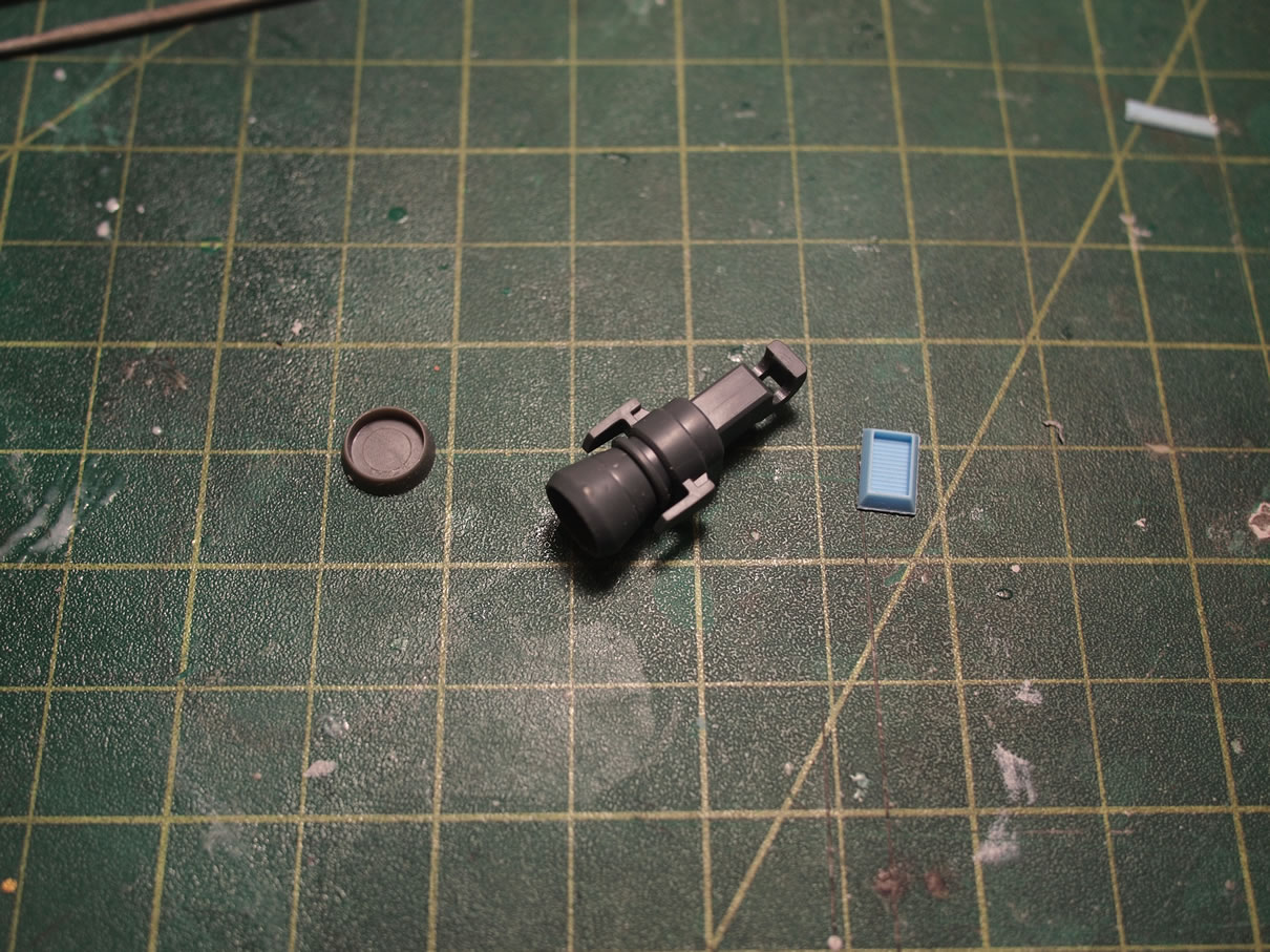
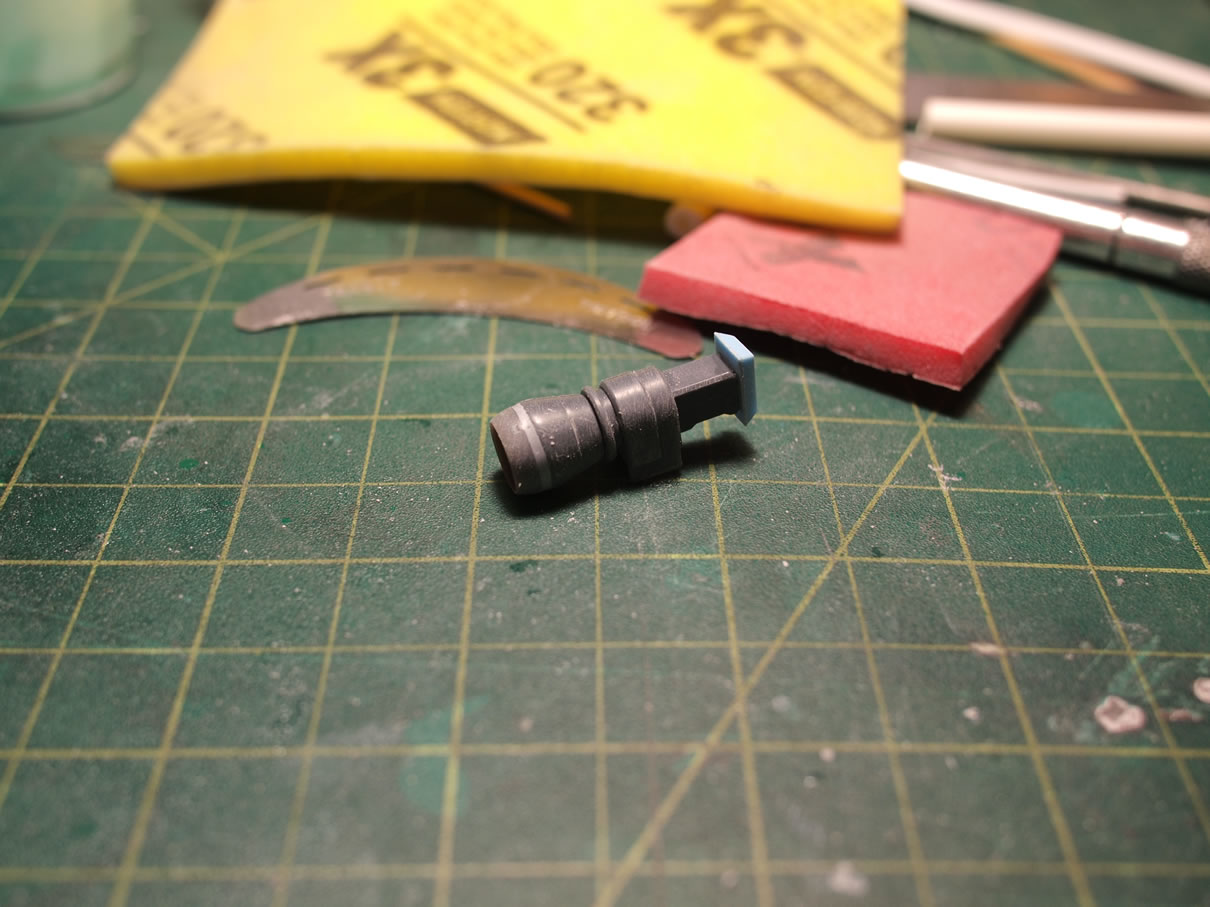
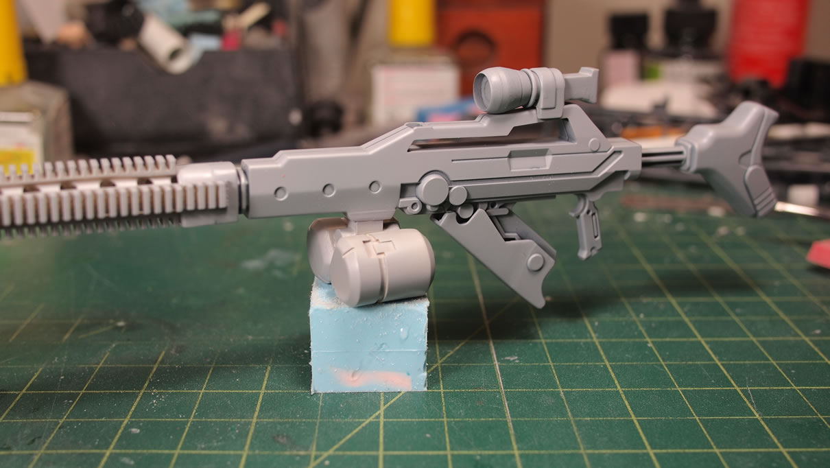
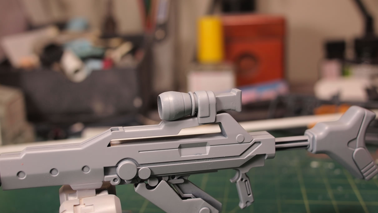
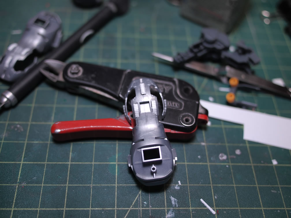
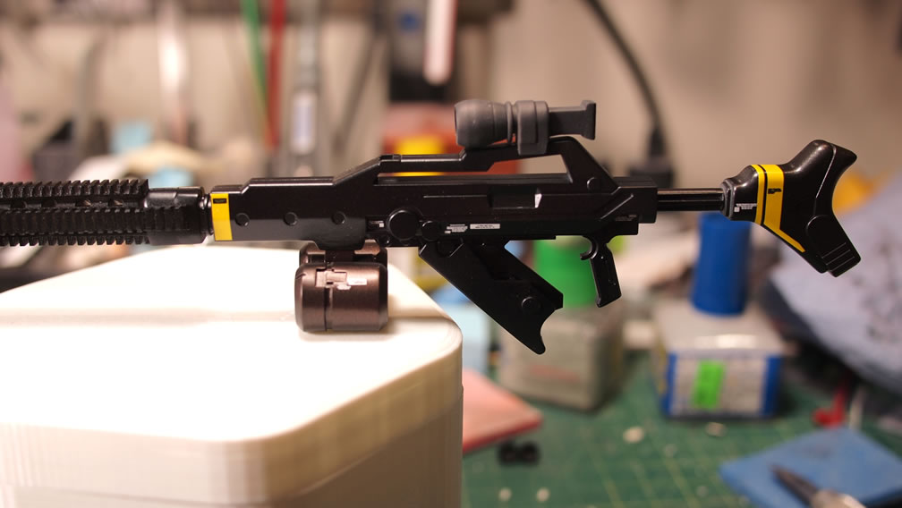
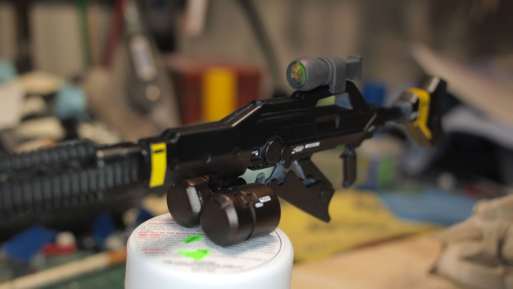
Since I had cast most of the thruster part, I had one of the foot thruster pieces in my work space. Turning it around it made for a fairly convincing scope. A circular mold from the wave option parts is cut and glued to the end of the thruster bell. Once cured, putty is applied and more areas are filled with stacked plastic. Sanded down and mounted onto the rifle, the little thruster engine piece works perfectly as a scope.
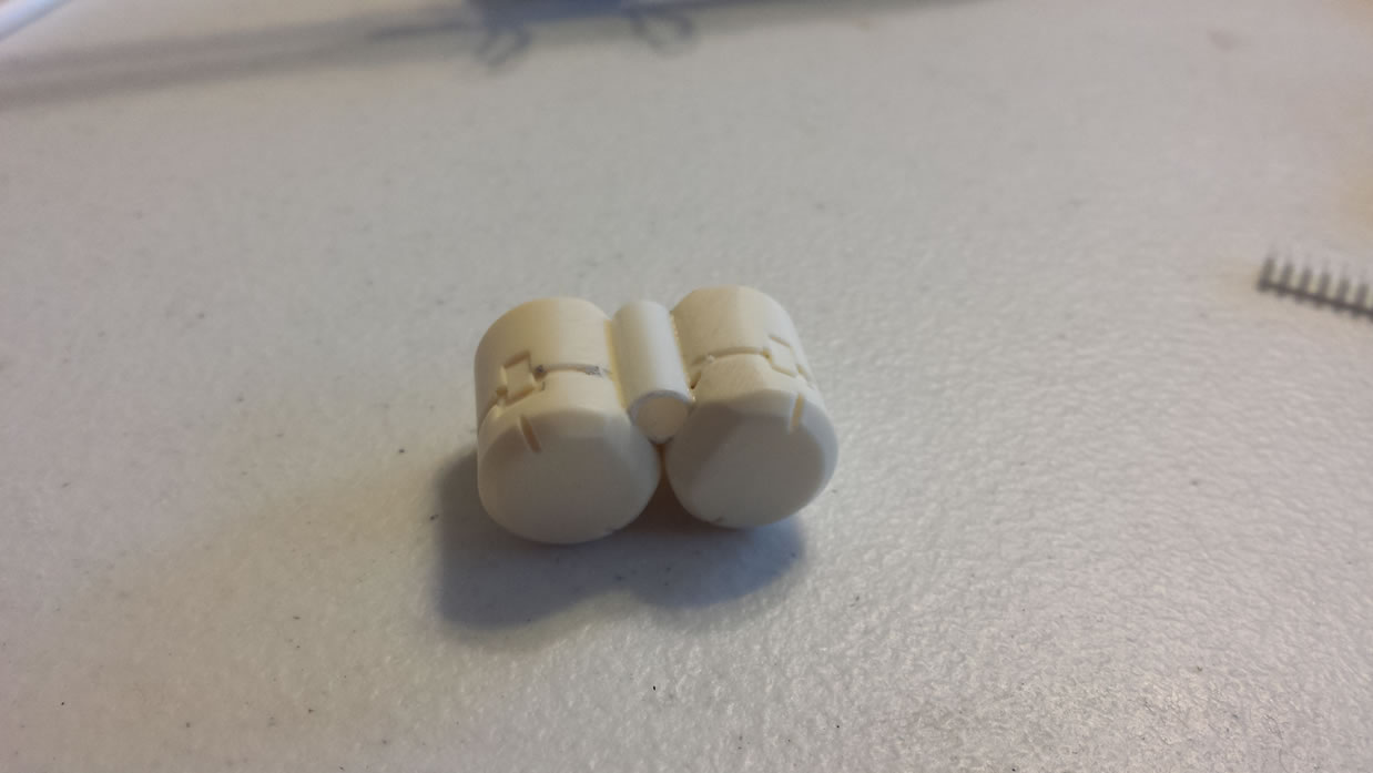
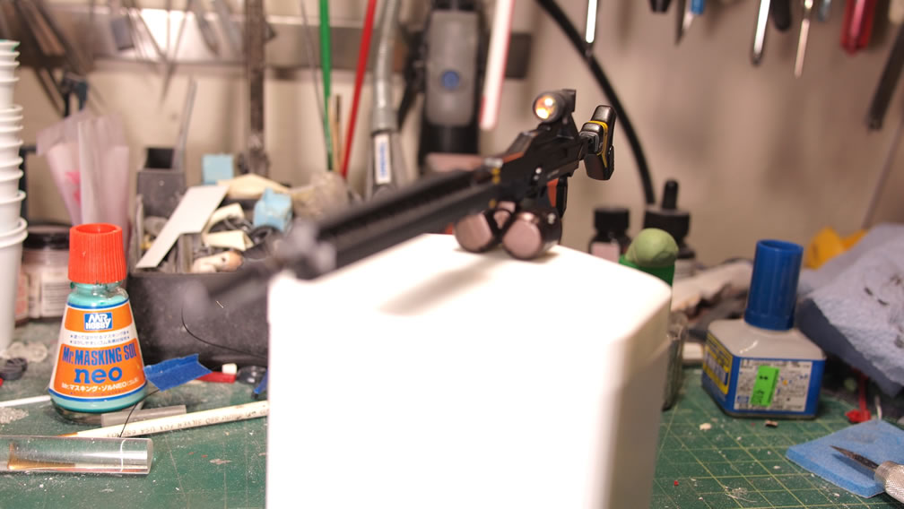
I made casts of the cylindrical piece from a resin Ore Gun set. With two copies, I applied sticky tack and connected them to the rifle for a test look. I want to use the Ore Gun’s part as an ammo drum, but felt I could use a dual ammo drum. Granted these do look like a set of balls, but I still like the styling.
The next step was to find a way to combine the two drums and attach them to the rifle. The drums are attached with a cut piece of styrene tube. The insides were filled with smaller styrene tubing as filler and then puttied. I added a resin vent piece to the bottom of the rifle as an attachment point for the drum magazine.
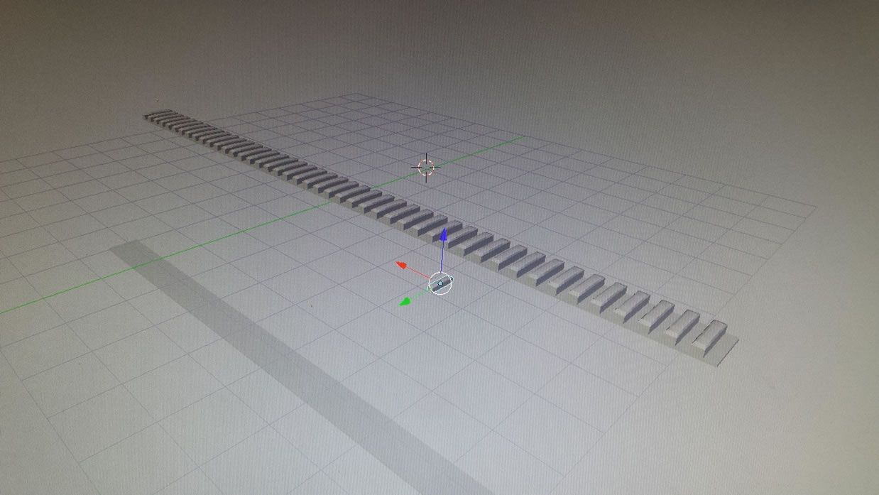
Taking a break from the work bench and on to my computer, I designed a rail with Blender 3D design software. In the past, I have just made the rail from styrene and cast in resin. I still had the original mold, but I figured this was an opportinuty to try printing my own design. Recently, a few of us from TGG started looking into getting a 3D printer. A few of us have been looking at one for a while now. The problem is that none of us know a damn thing about 3D design, or have used any 3D design software. I started with Blender, did some work with Solid Works, and opened up a session in Zbrush. The point here is that I’m learning. So starting off with something basic, a rail, I made the design, and then ported it to a proprietary printer software for Makerbot. My work has the MakerBot Replicator 2 3D printer.
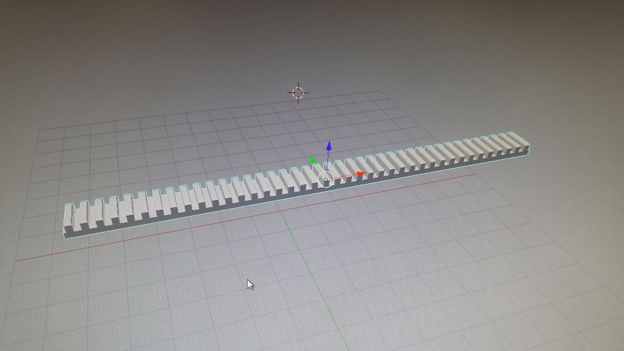
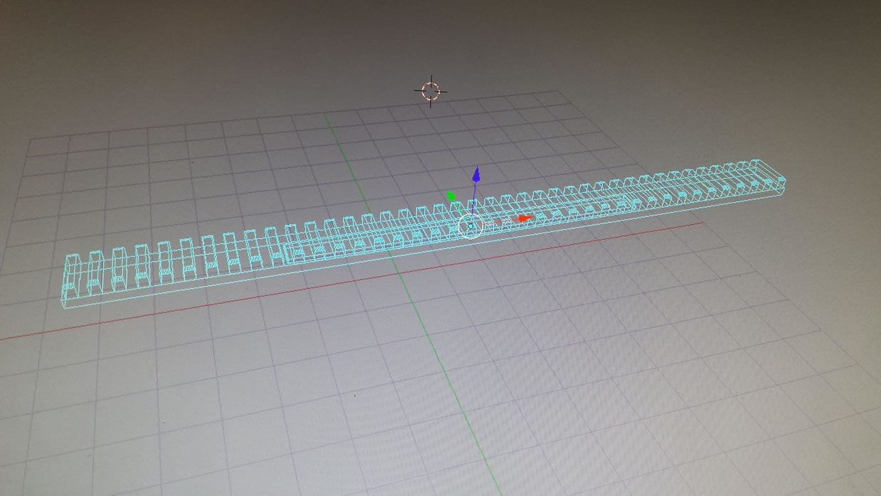
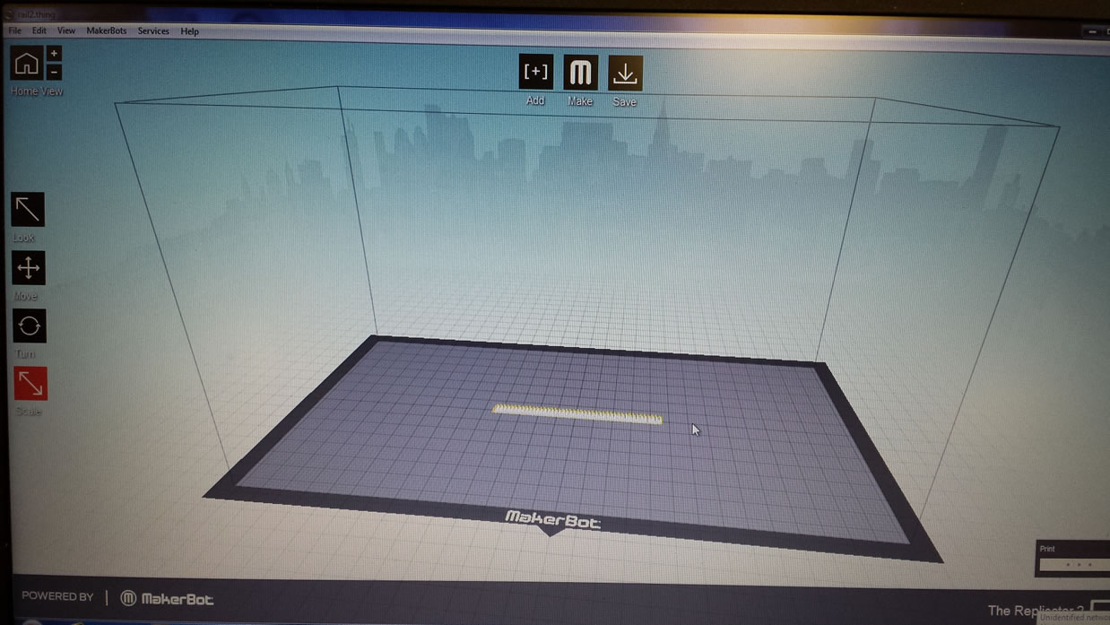
So aside from learning to design for 3D printing, I need to learn how to actually print and use the software. The printing software is a much easier learning curve than learning the software to design things. But with my designed rail, I imported it into the makerbot printer software, oriented it, scaled it, and then printed it out
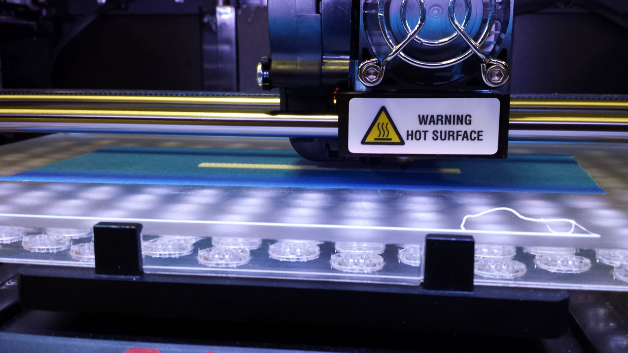
My first couple of prints were some what a failure. The rail came out, but without tops. So returning to the design software, I made some changes to my design and tried another print. A little too small. One print session, the PLA stopped feeding. Learning the quirks of the printer, I finally got a good master printed that require little clean up.
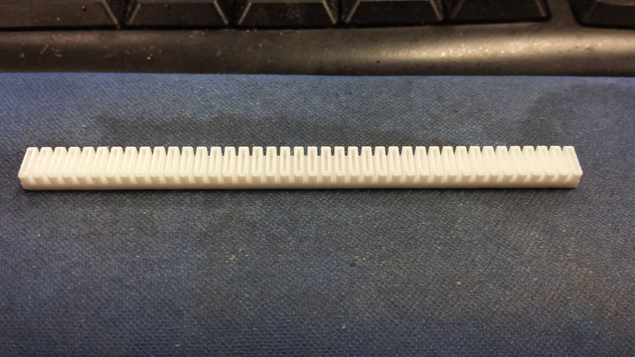
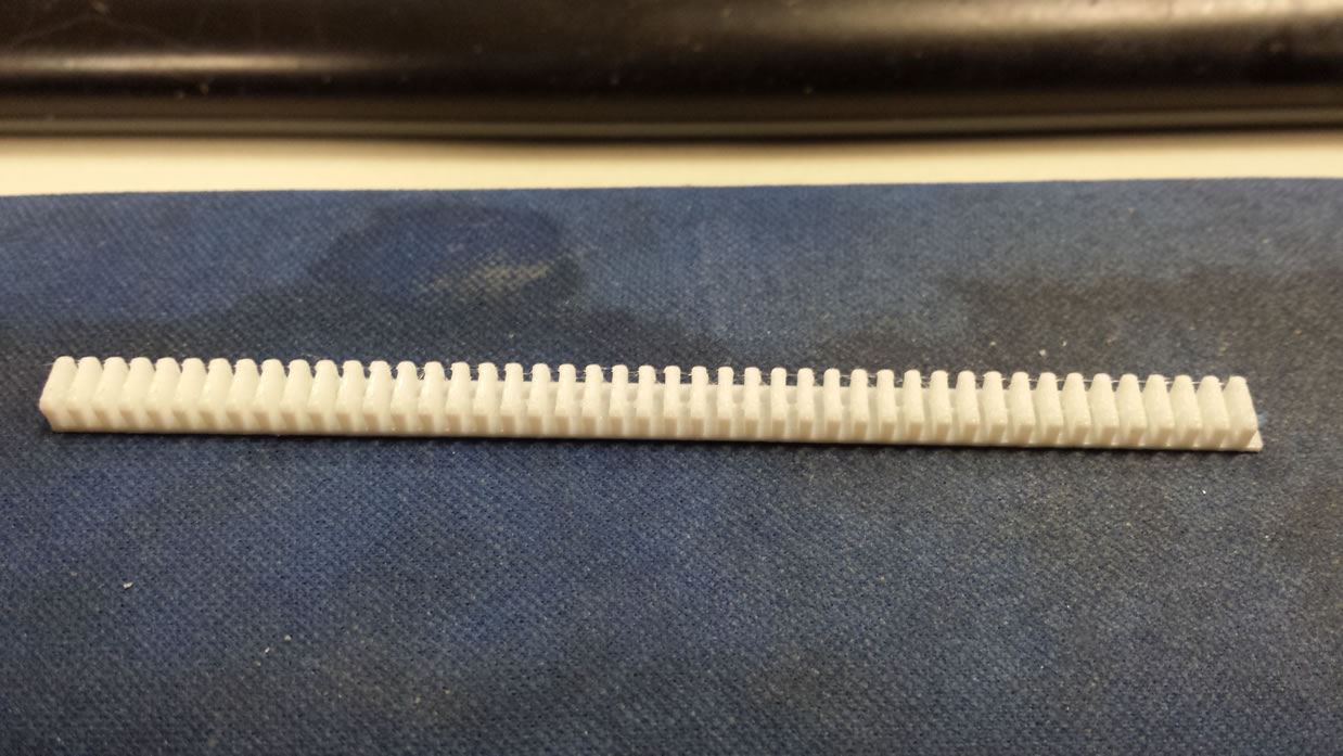
The master was cleaned up and a silicone mold was made of it; then the part was cast in resin so I had several identical copies. Now in comparison to the build it out of styrene method, the precision and scaling just kills what I did previously.
After some more sanding on the rails to lower them a but more and a few touch ups on the scope and putty here and there between new and old parts. The rifle gets its first layer of primer. Now the gun is starting to look a little more together instead of a bunch of parts slapped together.
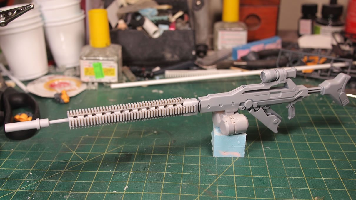
Next, I’ll be working on painting the rest of the kit and getting the rifle completed.
March 4, 2014:
Sazabi work continued on the arms, lower torso, and skirts, up until Brian showed up in town. So I had gotten the parts masked, painted, unmasked, and sprayed the two tones of clear red. That’s about as far as I got and Brian came into town; so all work halted.
I got some more painting in for the rifle and thruster parts, and started assembling the front and back skirts. There is a little bit of detail on the front skirt that has a cut out for one part of the detail, and is solid for another. It looks like a design decision with the whole psycho frame opening thingy. Well, that part was masked around and sprayed. Not too difficult.
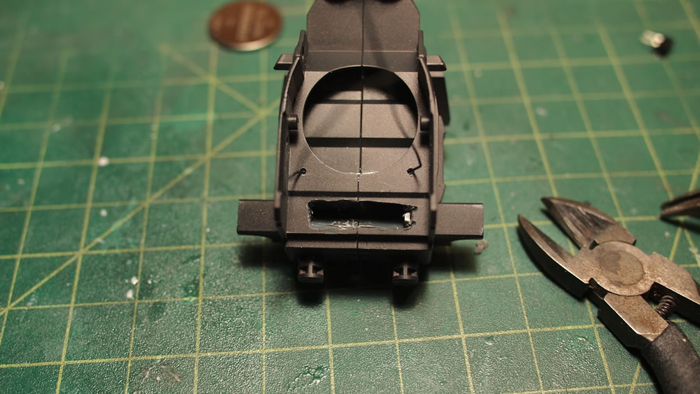
Since I’m going to show the arms now, I need to go back to the beginning of the build to where I glued some styrene over some holes in the forearm armor. I think this is for the shield attachment or something, but I just didn’t care for it, so I covered this up. I think it looks better than the holes.
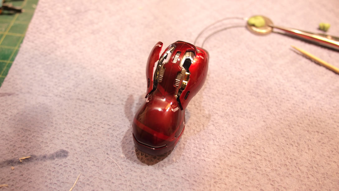
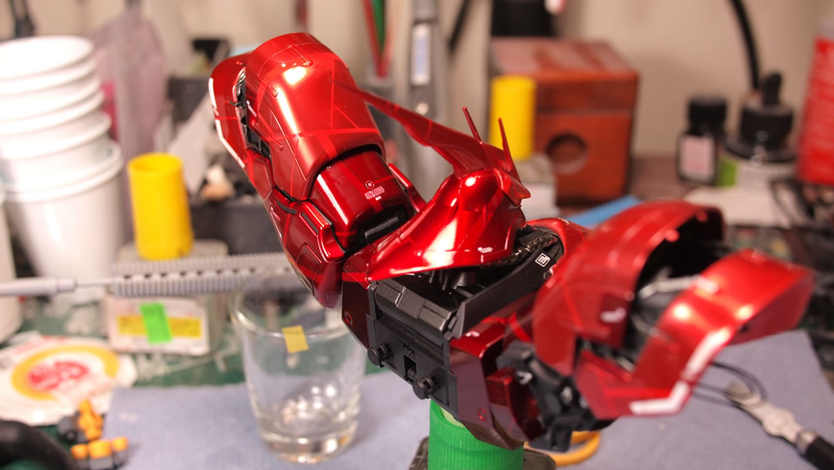
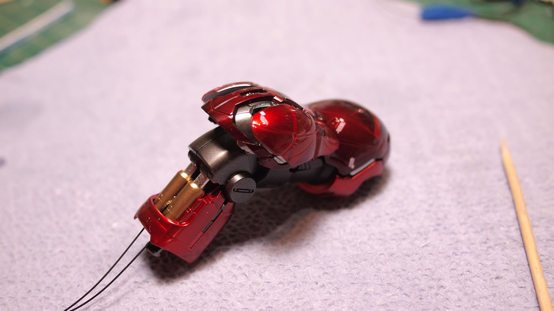
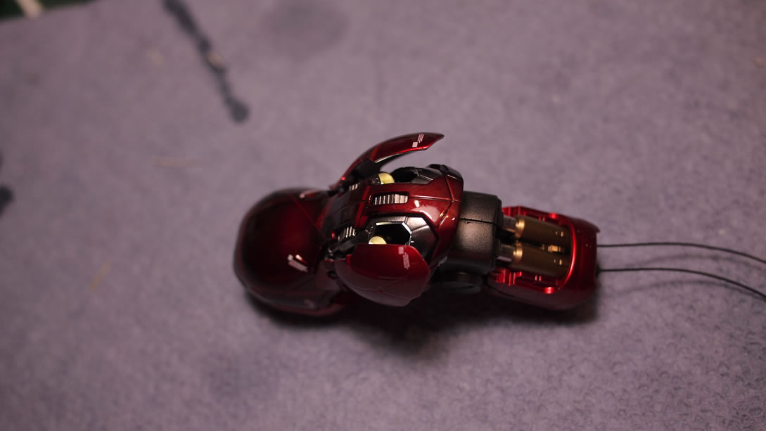
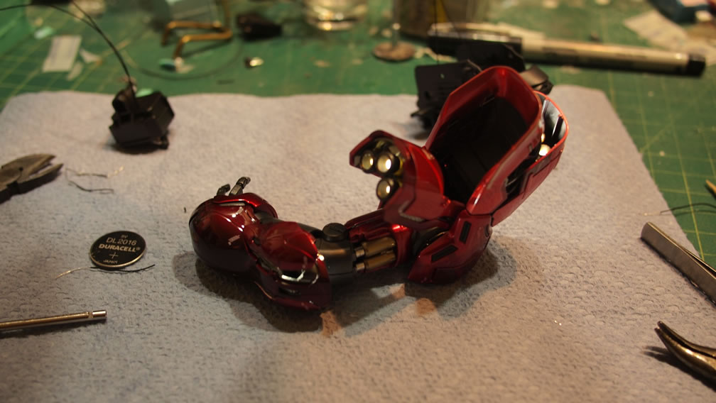
Last night, I assembled one of the arms. The wiring is threaded through the pistons and up through the arm, so they’re hidden. And attaching the battery for a quick little test, the thrusters are lighted up nicely and the arm piece is probably riddled with my finger prints as I assembled the piece without my soft cotton gloves. A quick little wipe should remove those and the part is pretty much done.
I have the other arm to put together then it’s on to the legs. Hopefully I’ll be done in another couple of weeks or so.
March 24, 2014:
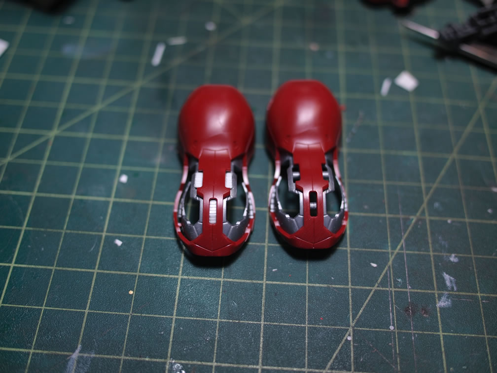
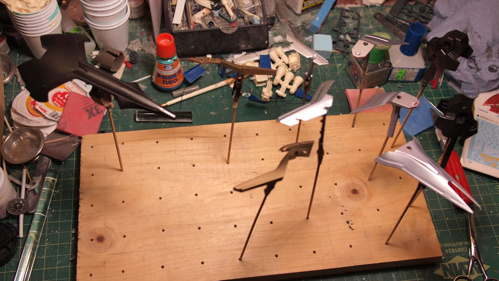
The last third of the third building group, the legs, get painted in the same fashion as the other two sections described in earlier posts. White base over the grey primer, masking, metallics, unmasked, the clear reds.
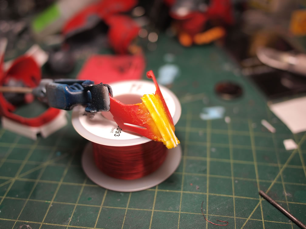
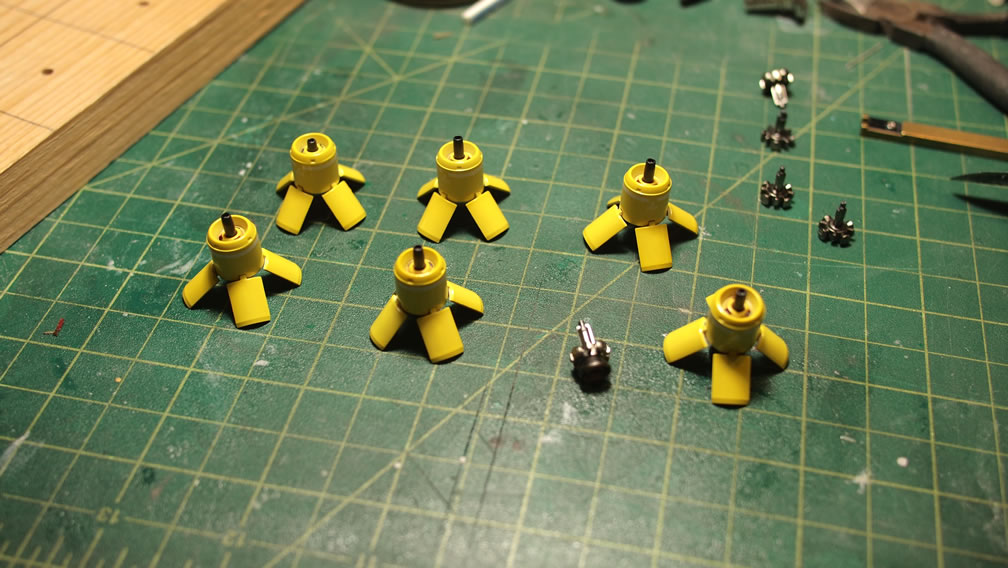
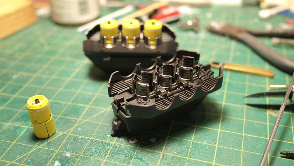
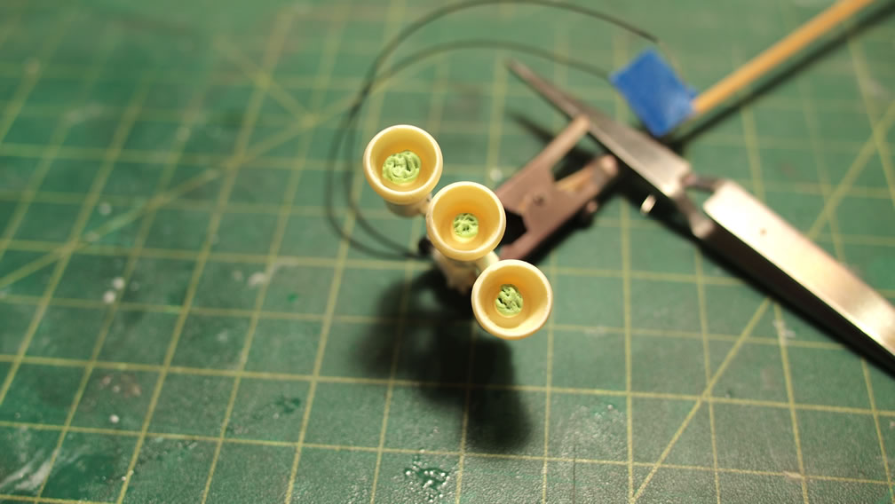
I decided to use the funnels as a means to break up all the red, so I first sprayed them with white base. In hindsight, I should have first sprayed these red parts with mr color primer, then sprayed the white base. Too much red was bleeding through the white. Over this white, I sprayed Mr Color clear yellow, so the funnels are a bright lemon yellow. The internals to the funnels were painted with various metallic tones and then assembled and decaled. With that done, they were assembled into the funnel pods.
The rifle progress was shown in an earlier post. I finally got that finished with paint and decals. The main rifle was sprayed first with Mr Color Metallic Black (Metal Black) depending on what label you stumbled upon, but it’s the same product number. Over this to lower emphasis on the rather large metallic flakes, I sprayed alclad gun metal with worked to tone things down slightly.
Close ups for the rifle. The scope lenses were done with aurora stickers from ako hobby. The silencer got a dual tone finish with Alclad burnt iron fading into the Mr Color Metal Black/Alclad Gun Metal combination.
The LEDs embedded in the resin thruster parts were masked off then painted with Alclad steel. The backpack thrusters were cut up and LEDs were fit into the spots and wired up internally. And a quick test with a battery ensures it all works.
One of the things that made working on this project so fluid with cutting up the kit into three sections was the decals. Doing the kit in three distinct parts was similar to working on three distinct kits. Paint, decals, clear. The decal sheet for this kit was fairly daunting, so cutting up the kit into three parts really helped. The following decal layout is for the lower leg pieces only.
With everything painted, decaled, and clear coated. A few days of curing was set for the parts before they were masked to paint the small details. I could have easily gone in and hand painted these little details, but the texturing would have been completely off. So parafilm and sticky tak was used to mask off the areas for some quick sprays of Alclad burnt iron.
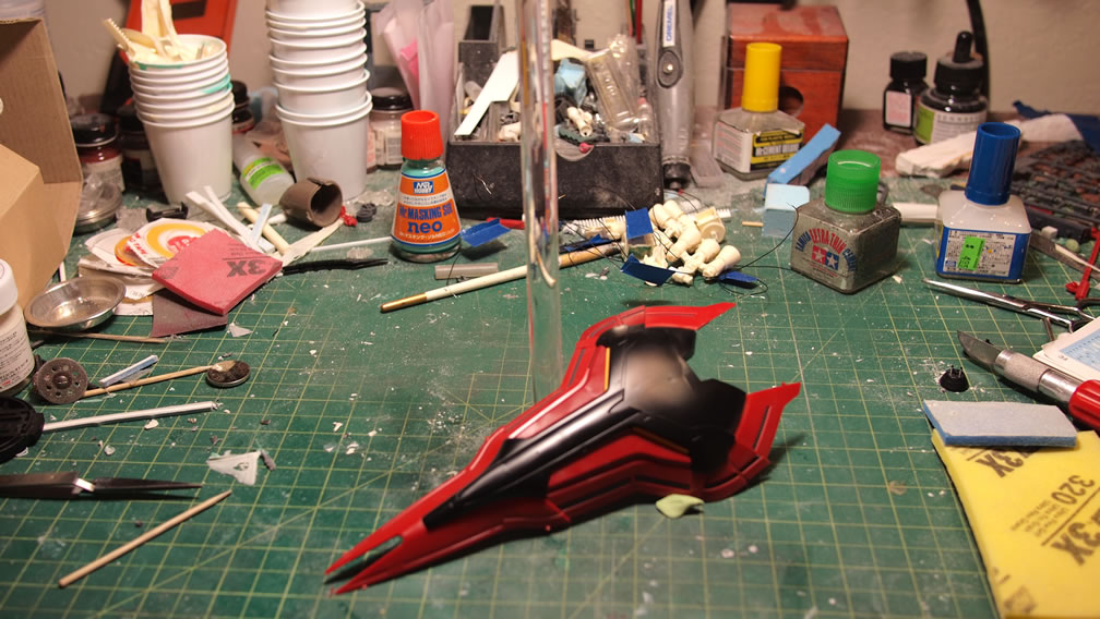
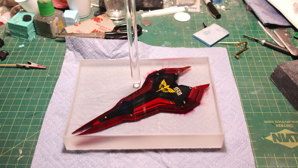
I love the Sazabi design. I love the shield. However, having the Saz holding the shield obscures a good third of the body and work, so this is my solution to displaying the shield with the kit. Use the shield as part of the base. And for a base, I wanted something simple so as the focus on the display is the Sazabi, not everything else around. The solution, encasing it in a block of clear resin.
Starting off, the kit was built, painted, and decaled. In hindsight, I should have let the damn parts cure for a full week and/or clear coated the parts before rushing into the next step.
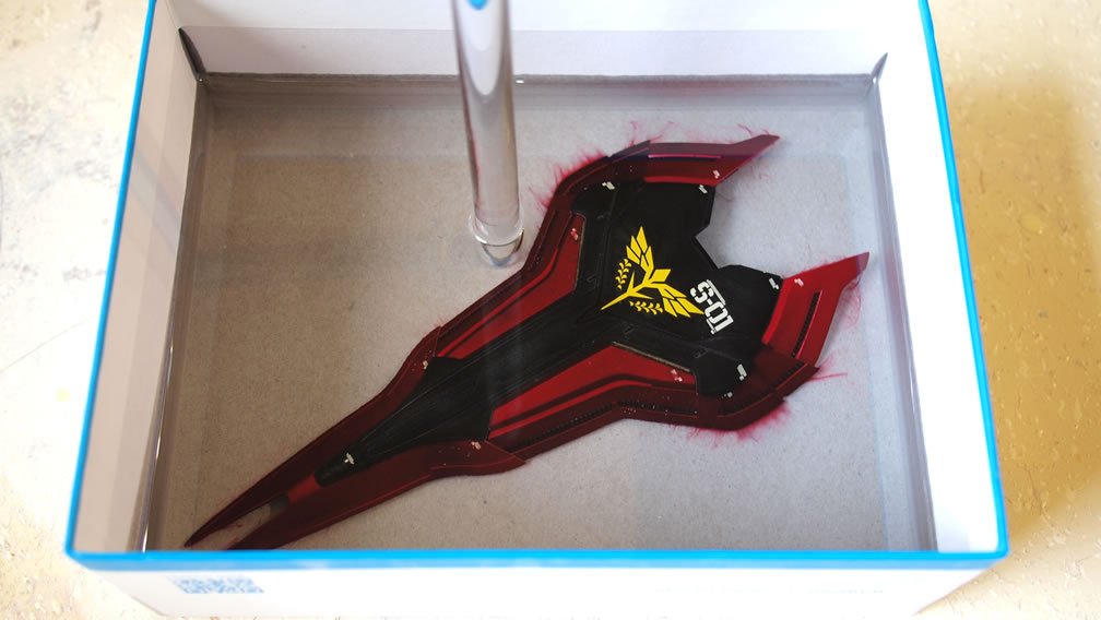
Using a box from my Resin SD Kampfer, I first layed down a thin layer of polyurethane clear resin. That dried and cured fairly quickly, and since the box didn’t fit into my pressure pot, it had to be cured in the normal atmosphere. So since the urethane cured so quickly, there are a decent number of tiny bubbles trapped and visible as the bottom most layer.
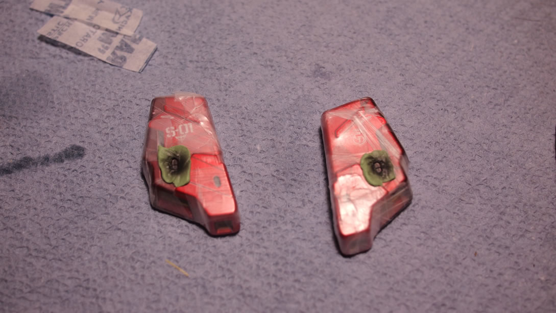
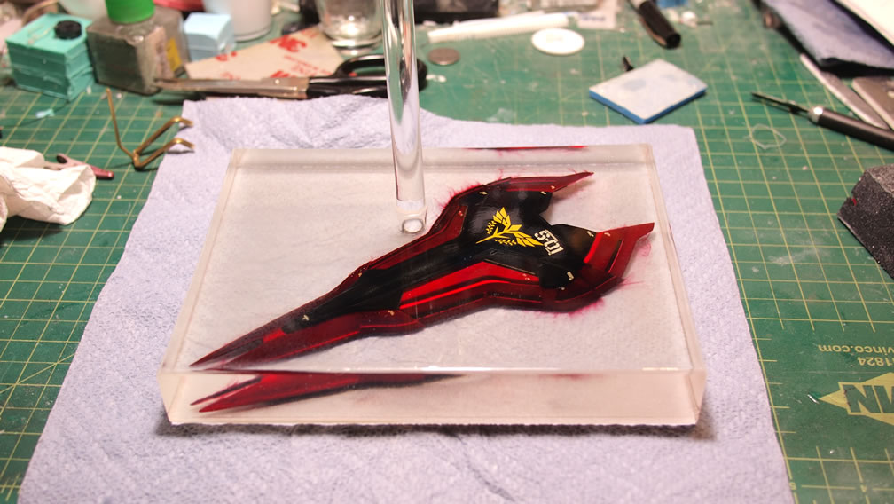
With the base layer cured, the shield was placed into the box and I mixed a large batch of enamel clear resin that has a much slower cure time. The slower cure time also helps as the process isn’t as exothermic as the urethane resin curing. It would be a horrific shame if the curing clear resin melted the shield. However, I wasn’t completely unscathed, not allowing the paint to cure and not clear coating it led to the paints bleeding. Granted it does kinda look cool, but it isn’t what I was intending to do. To quote Bob Ross, “we don’t make mistakes, just happy little accidents” I guess.
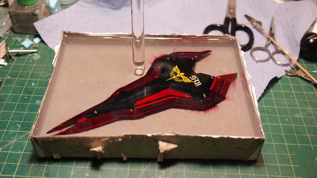
The first layer of enamel clear resin didn’t cover the entire shield, so it was left for about a day and a half to solidify, then another layer of enamel resin was poured. This layer found yet another “happy little accident”, and bubbles from air trapped within the shield surfaced. The resin cured for another day and a half so the bubbles were hard enough to cut apart and clip off some of the excess. The last layer of enamel resin was poured, and using a bamboo skewer, I poked around the bubbled areas to ensure that the resin filled in those spots, and that really worked to help remove the bubbles from the previous pour.
The resin pouring process happened a few weeks ago, and after checking the hardness over the past week, this weekend was good for finishing the base. The box was cut apart, but some of the box is still sticking to the cured resin. After all, resin is an adhesive. So with most of the box cut off, the entire block and clinging cardboard was soaked in water for several hours. Soaking helped peel away more of the cardboard. Another soaking session removed the rest of the cardboard, but left a sticky residue. The residue is sanded away leaving the clear resin block free of any paper products. A quick spray of clear gloss along the sides makes everything water clear.
Last week saw the wiring from the painted resin thruster pieces through frame parts of individual sections. Each leg piece holds three separatly wired LED assemblies, the front thruster, larger rear thruster, and the 3 part rear thruster.
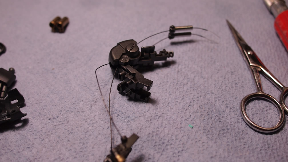
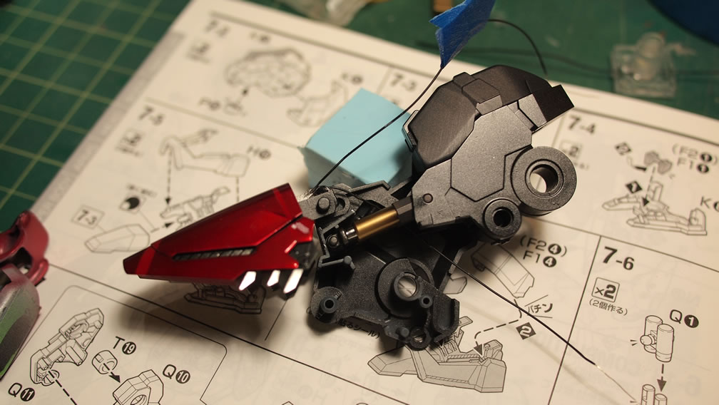
As the leg is assembled, the wiring is threaded through and the three sections are wired together at the back of the knee area. Below is a comparison of the mess of wiring with the wires tied together neatly to form a single positive and negative pair that is then threaded up the rest of the leg. The wiring is tested out to make sure all three sections are lighting up.
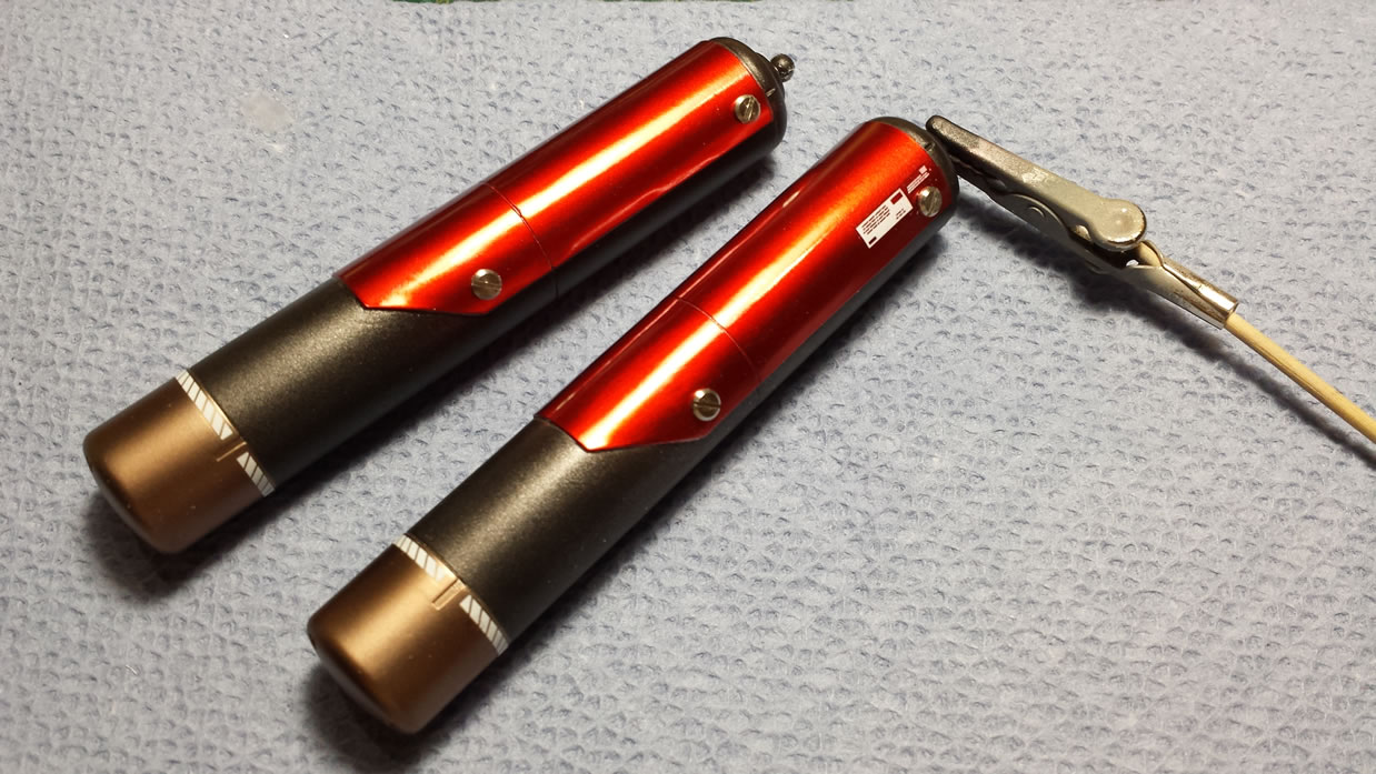
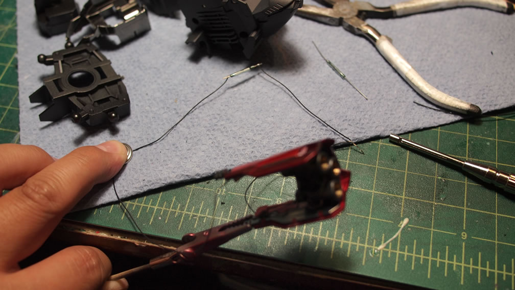
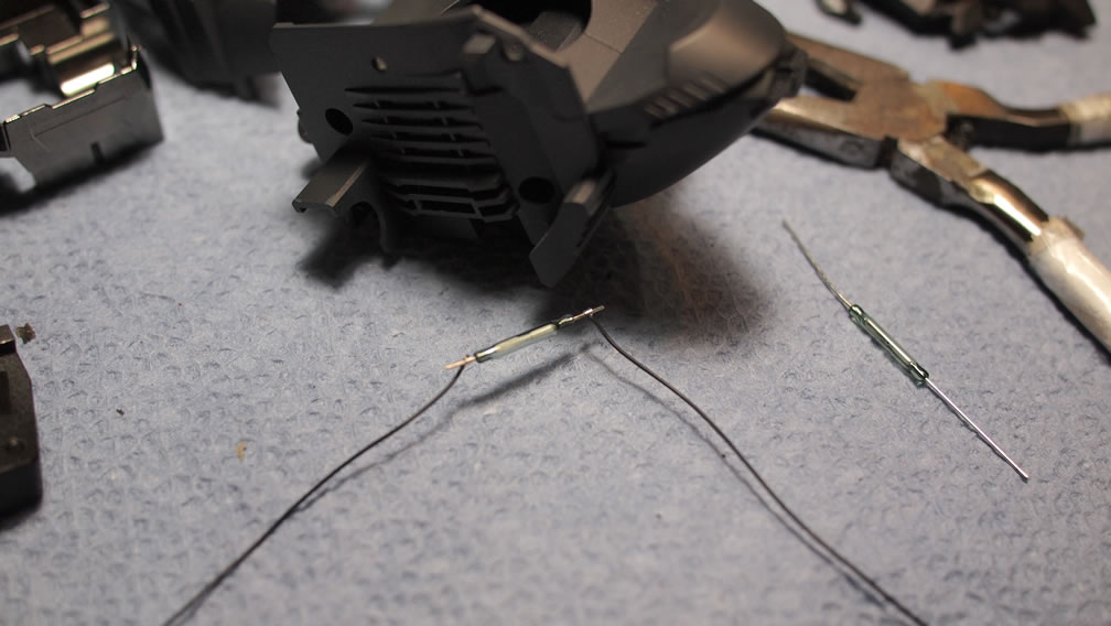
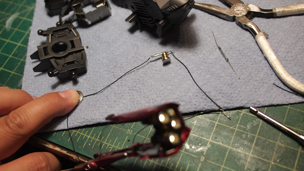
Next up is the reed switch assembly and test. The reed switch is a magnetically activated switch and makes a connection with a magnetic field is close by, in this case, a small rare earth magnet. From the LED assembly, the positive end is run to one end of the reed, and continued through the other end of the reed switch to the positive end of the battery source. The negative end of the LED assembly is run directly to the battery. The reed acts as a break along the positive wiring. Connecting a magnet, the wiring is completed, lighting up the LED assembly.
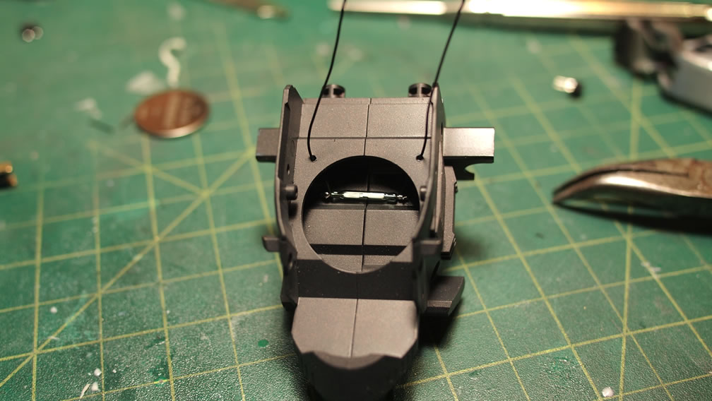
With the test successful, the reed switch goes into the neck/collar piece. It is wired and glued into position.
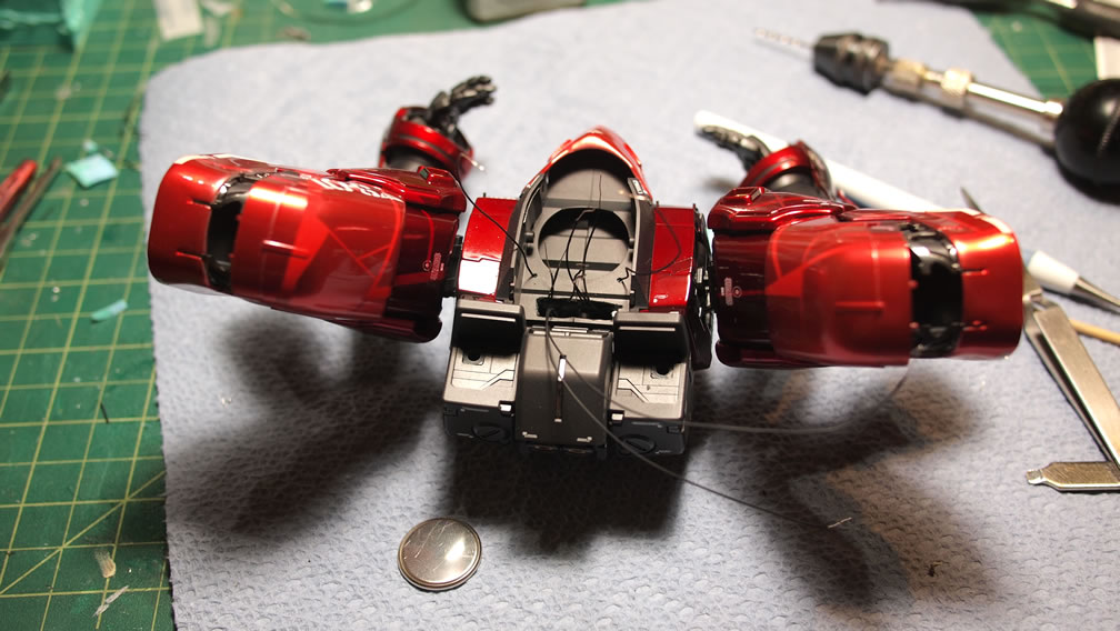
Returning to the arm sub assembly, the three thruster parts here are threaded and wired together similarly to how the legs are wired. Three parts combining into a single positive and negative pair that runs out of the lower shoulder connection joint. A quick test of the arm lights show that everything works.
The arms and backpack are assembled to the upper torso piece along with the battery and reed switch assembly. The negative ends are threaded through the body and wired together as well as the positive ends wired together and connected to one end of the reed switch. The other end of the reed switch connects to the battery’s positive end. The negative end just connects to the combined negative wires tied together.
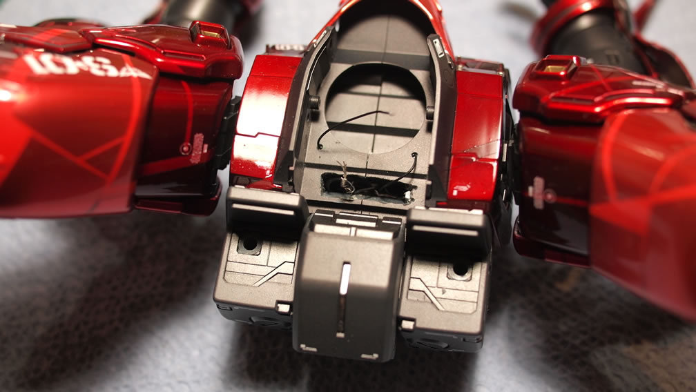
Another quick light test of the upper body, this time with the battery and reed switch assembly. I’ve also added a simple connection that runs down the length of the upper torso. The waist will have a companion connector point so that the entire suit is wired as separate upper and lower entities. This will make traveling with the kit easier.
Lower torso is wired together, the legs and waist skirt lights are combined along with the connector piece.
With the wiring completed and the two halves of the Sazabi connected, I did a quick little video showing off the lights as well as the reed switch in action.