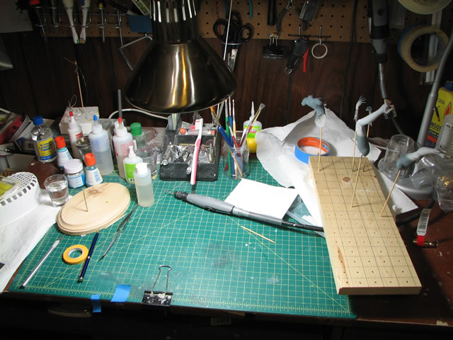
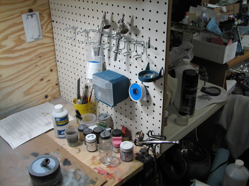
Feburary 3, 2007: Built a 3 part manifold for my airbrushes. So now I can run all three of my airbrushes at the same time. Ok, so I was bored and just wanted to build something that will probably not be used, but I don’t know until I build it. Hopefully this will come in handy. Also took some updated pictures of my workspace and pegboard tool arrangement. As I work, it evolves so that the tools I use more often are more accessible. I’m sure this will continue to evolve. The goal here is make my working environment as fluid as possible which promote quicker building and such. At least I keep telling myself that.
 |
 |
 |
 |
 |
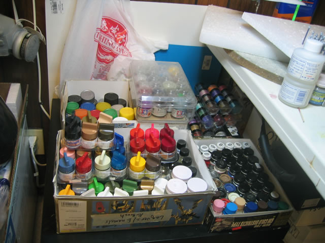
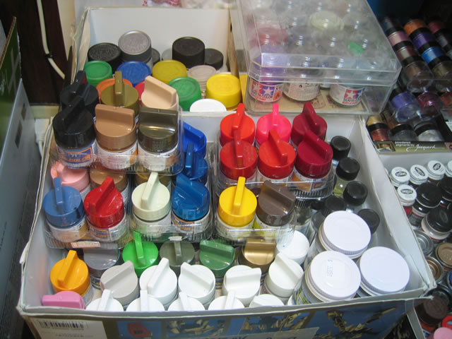
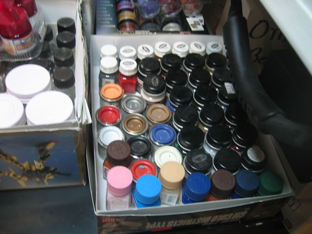
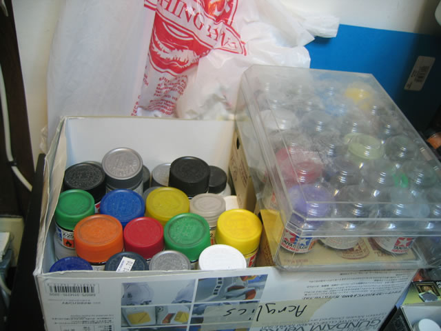
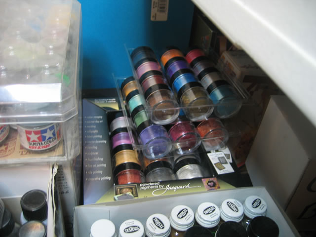
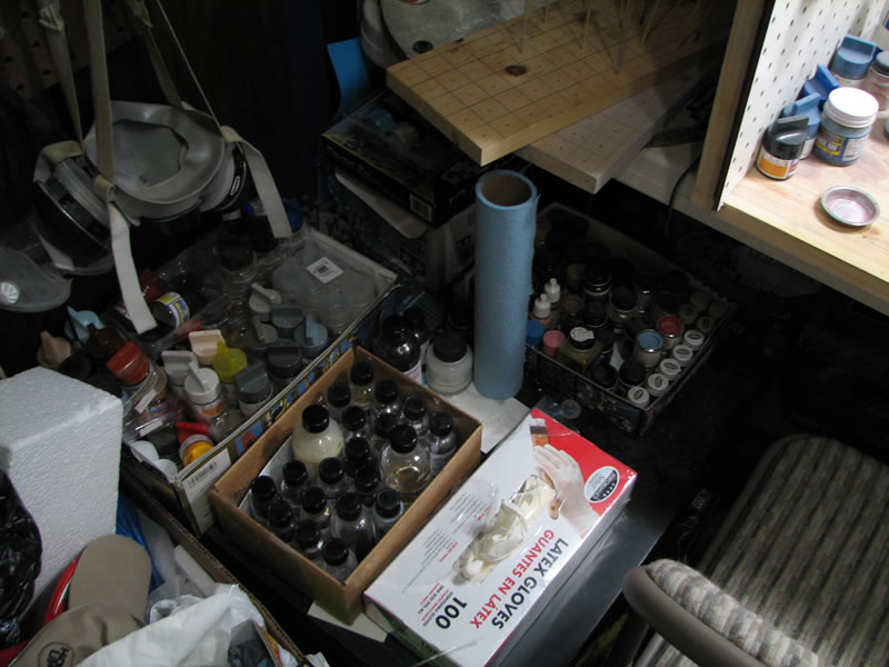
The next set of pictures is my new paint storage table. My paints are organized by type: Mr Color and Alclad II lacquers; Model Masters, Tamyia, Testors, and Humbrol enamels; Tamyia and a few Mr Hobby Color acrylics; and finally Pearl Ex pearl pigments.
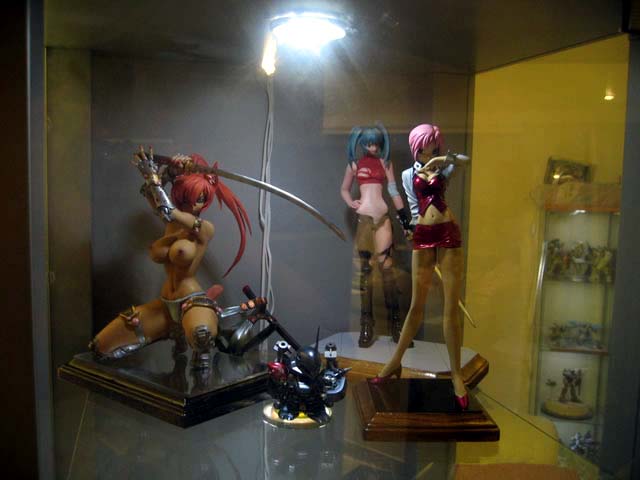
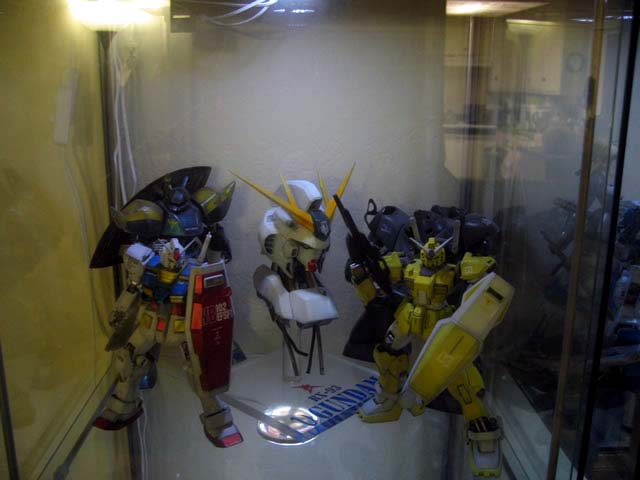
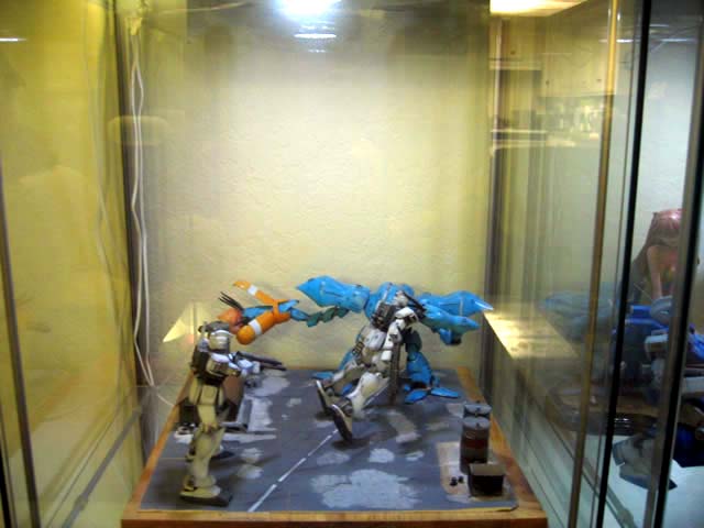
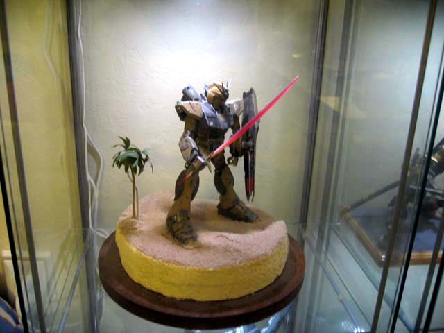
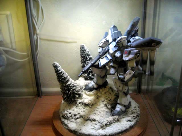
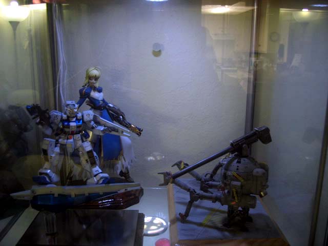
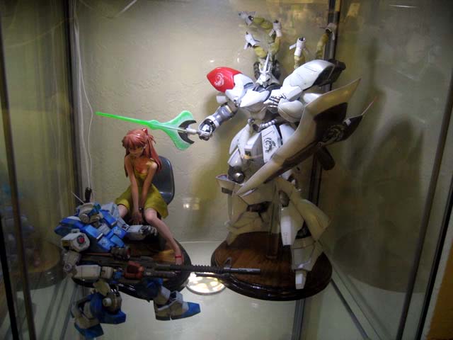
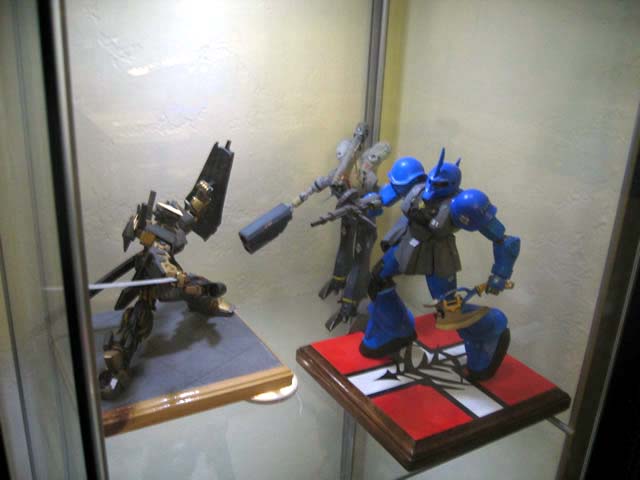
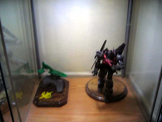
March 31, 2006: Added some Ikea LED lights to my display cases so took a few pictures of my displays. Crappy pictures yes, but with the current lighting and such, this is the best you’re going to get. Besides, the better pictures are peppered all over this site.
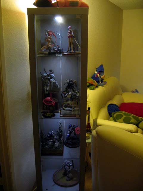
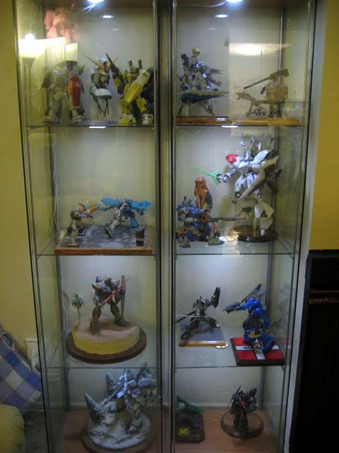
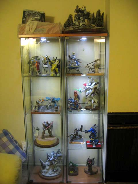
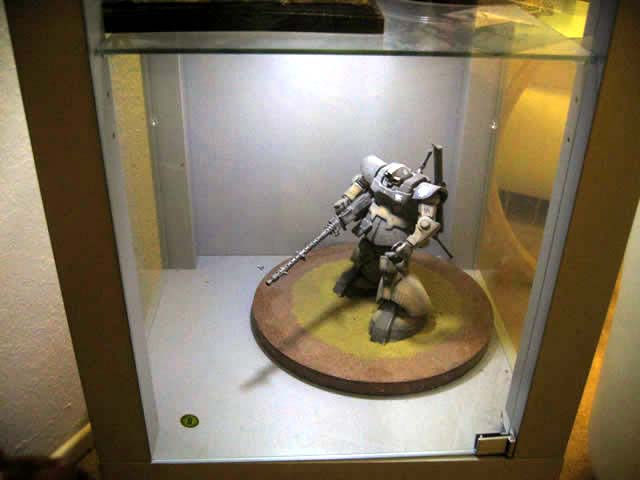
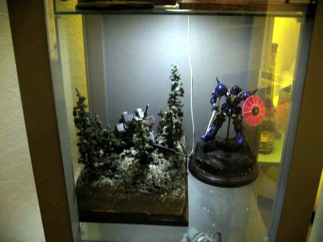
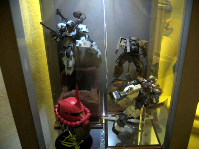
Inside the cases:
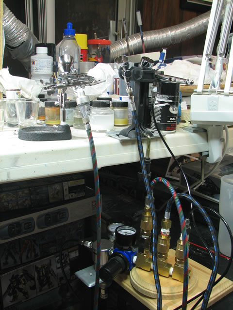
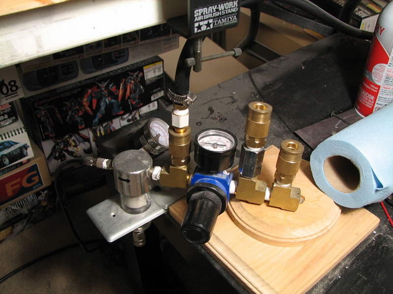
Airbrush set up: The following pictures are my current airbrush set up. At the time of this picture, I did not have an additional moisture trap that is attached directly to the airbrush as the last filter for moisture. But on with the set up.
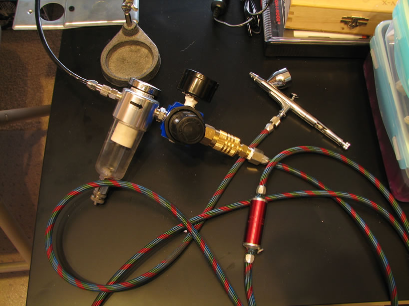
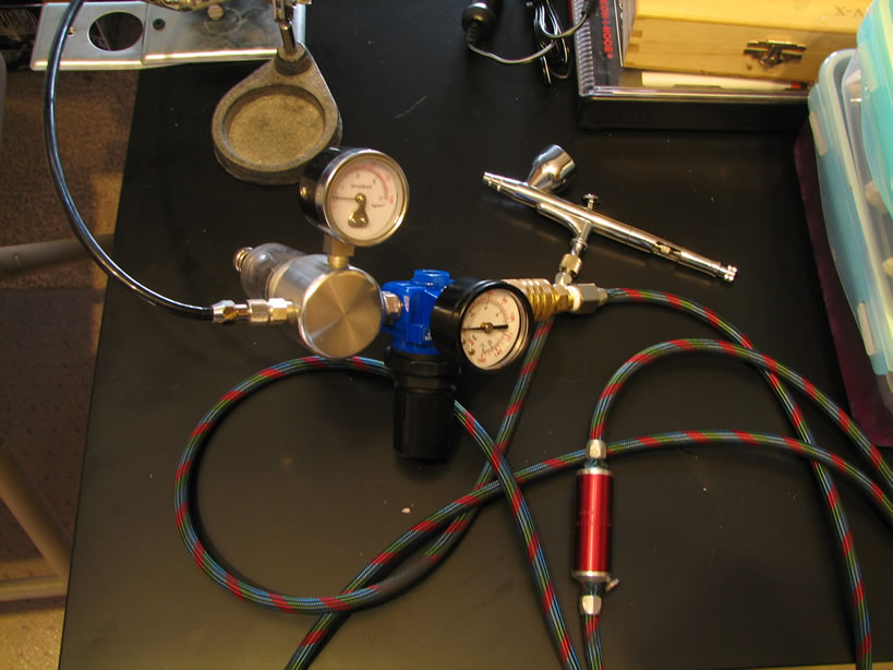
Moving left to right (sorta) the thin black hose is connected directly from the compressor. This first connection from the hose is to the water trap/regulator setup that came with my Iwata Smart Jet compressor. I didn’t like the way the regulator worked, so I added an additional regulator set up, which is connected directly to the Iwata water trap/regulator (the blue thingy). Now I really like the adjustment knob for this regulator, and the thing was about $20 at my local hardware store (lowes). Next is a brass quick connect plugs that joins my hose and the additional regulator. In the middle of the hose is another water trap. This is an inline water trap that is installed somewhere in the middle of the hose. I had to cut the hose then install this water trap. Finally, at the end of the hose is the airbrush connection. Again, I have an additional water trap that will be attached to the bottom of the airbrush coming; I’ll take new pictures when that item arrives. 3 moisture/water traps may be overkill…. but getting a sudden splash of water mixed in with paints while painting sucks ass.
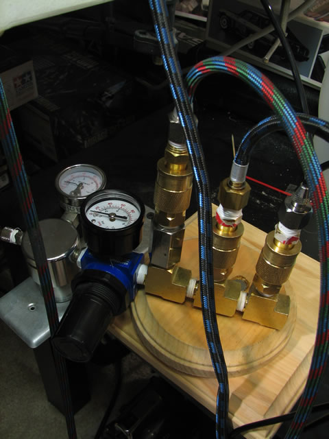
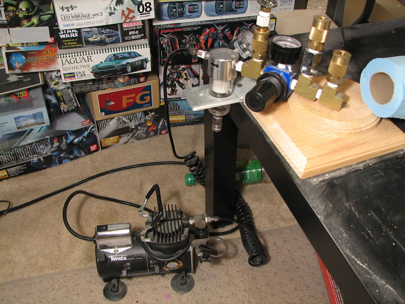
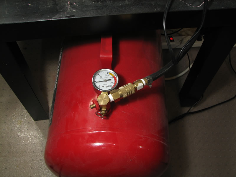
May 9, 2008: At a request from a fellow modeler, I took some pictures of my current airbrush setup since I recentely added 10 gallon tank to my previous set up. I had some trouble at first figuring out how to connect everything, but this is what I ended up doing.
- Starting with the compressor (on the ground in the first picture), the air line is hooked from the compressor to the moisture trap that came with the iwata compressor.
- From there, I have a manifold piece with 1/4 in fittings connecting from the moisture trap.
- There are three connections with the manifold, one from the moisture trap, one that goes out and in to the air tank, and another connection that is linked to my regulator.
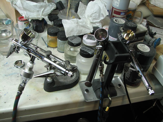
- Out from the regulator I have two more joint pieces that allow for two airbrushes, and if I wanted, I can tack on additional joint pieces to add more airbrush connections.
- The last picture shows the hose connected to the tank. There is only one thing connected to the tank and that is the hose, and it works to fill and expend air, essentially, the hose is an extension to the tank – and the tank is just directly connected to the compressor.
So when everything is opened up, and the compressor is turned on, the compressor only runs when the tank reaches below 40 psi (the setting on the compressor), with 10 gallons of air at 40 psi, my compressor only runs every now and then, and I get a lot more even flow of air with this current set up.
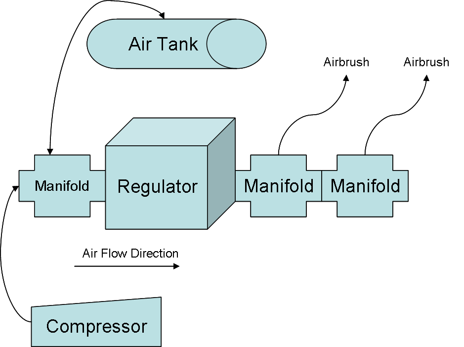
Feburary 25, 2010: Since a good number of folks have emailed me or asked me for the exact design for the air tank/compressor setup, here’s a drawing for the design. The arrows show the flow of air.
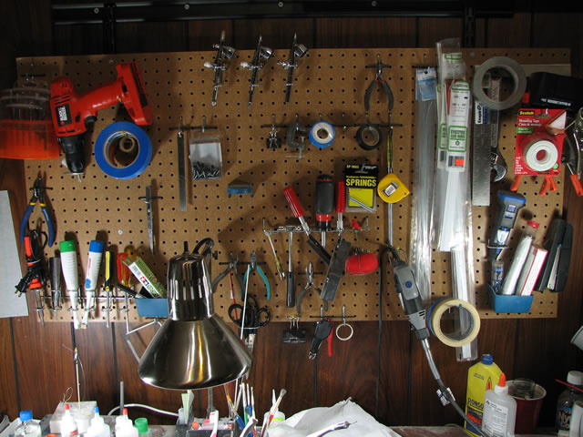
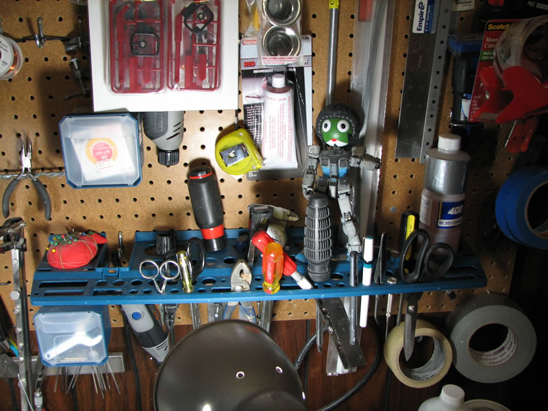
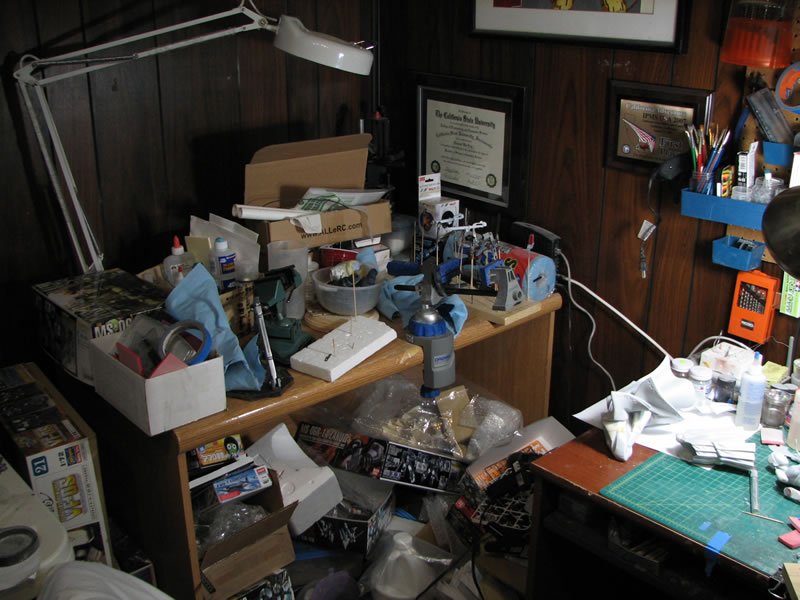
June 12, 2008: Recently, I did some additional reorganization of my workshop. Every now and then, the trip out to the local home improvement store finds neat tools and things that I can add to my wall of building supplies. The last trip, I stumbled upon these neat little trays of boxes that plugs right into my peg wall. I was able to free up more of my immediate workspace and create a much more fluid work environment.
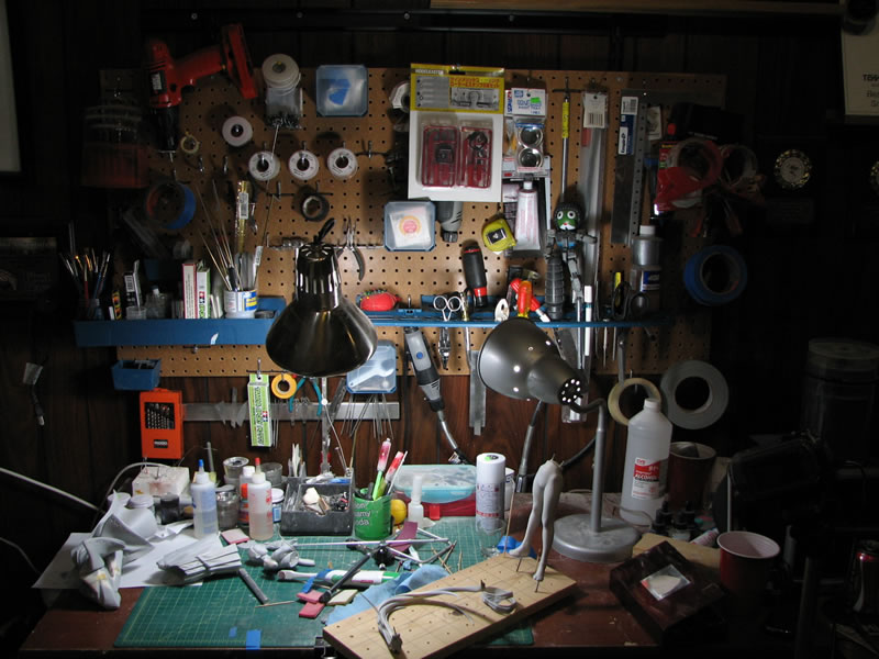
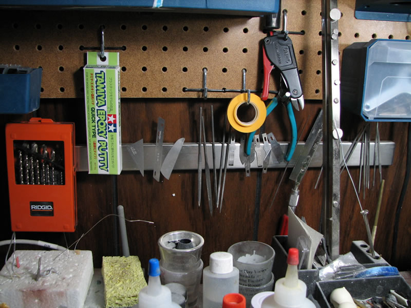
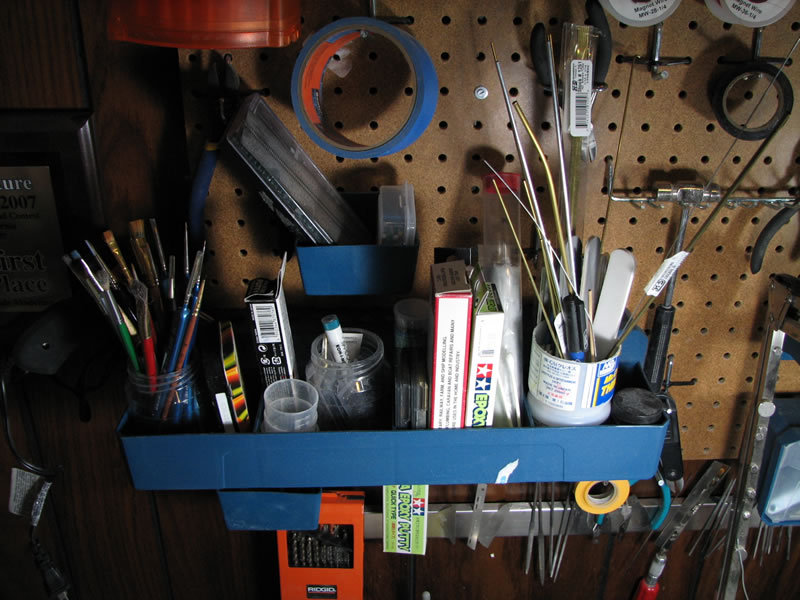
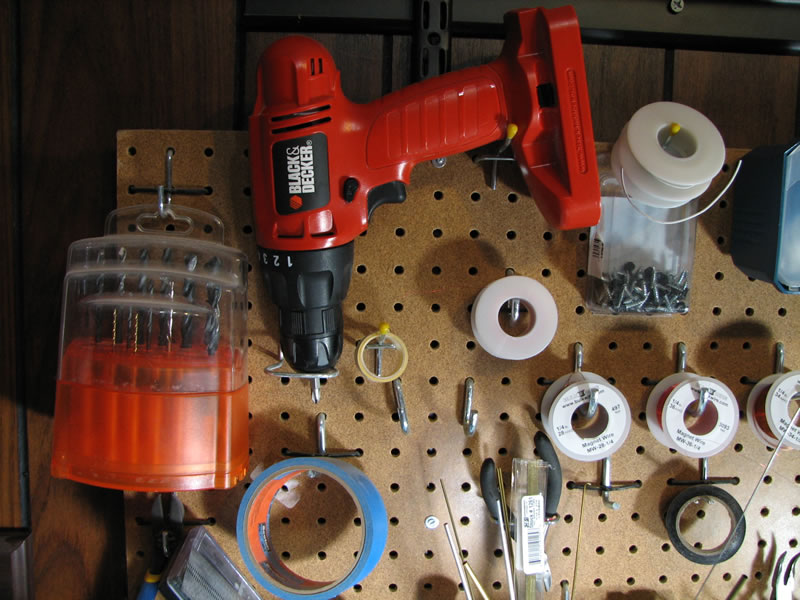
In the second picture, I found a nice magnetic strip that is used for kitchen knives. I bought two of these things at the local Ikea, and one is in the kitchen for the knives, while the other is here holding my files, little saws, hobby blades, and drill bits. Having this is amazingly helpful as I can reach these tools very easily. Next up are the various trays that I grabbed to further organize my peg wall.
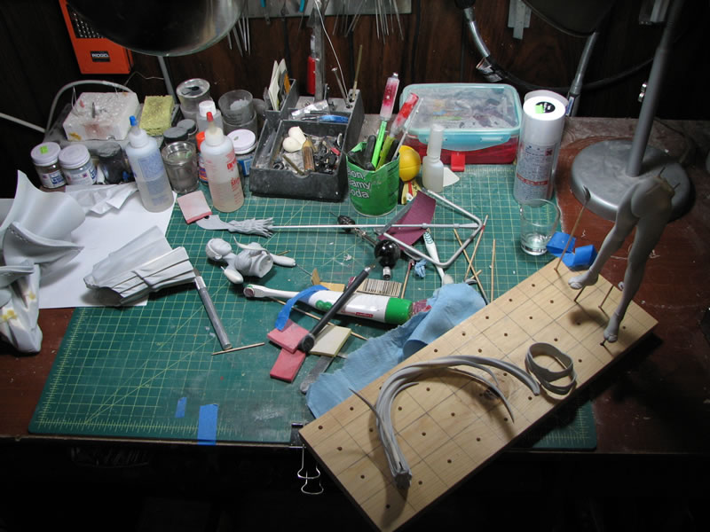
Next up is my work table, which is a giant cutting mat and next to that is an additional work table that I’m currently using as storage space, but most of the stuff can be freed up and an additional work space is created there.
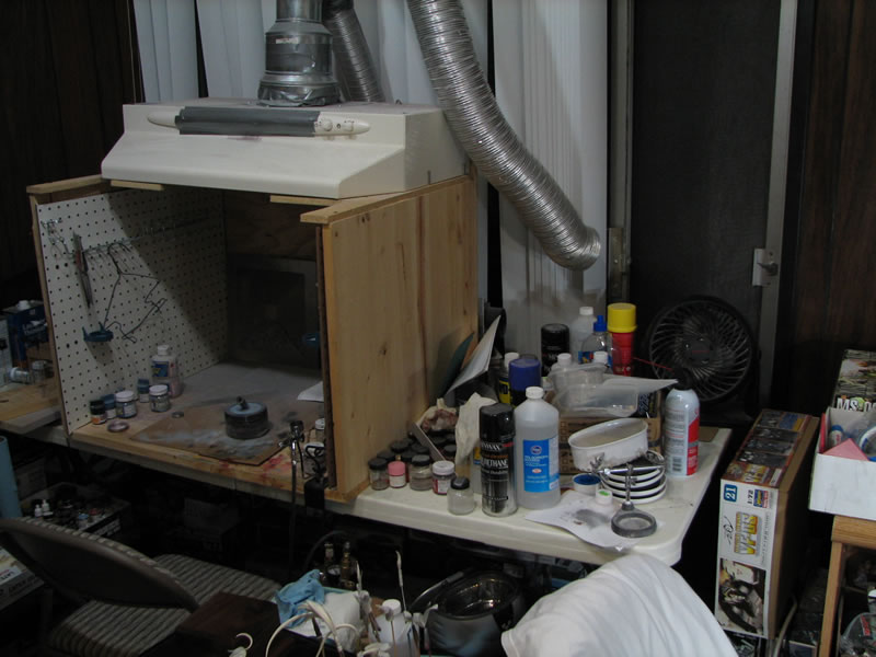
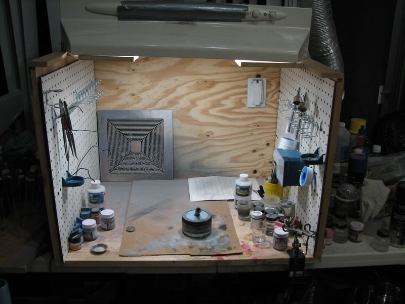
While updating my peg wall, I also decided to update my spray booth. The booth is fairly large, with a 30″ width, so adding peg board to each side adds some additional organization for immediate airbrushing tools such as additional airbrushes and other airbrushing related items. Immediately to my left of the airbrush is the paint storage area. This hasn’t changed and probably will stay this way as I’ve become accustomed to keeping my paints in that area. I’m sure that as I continue to work, my workshop will further evolve. This page will be a nice historical record of the workshop’s evolution.
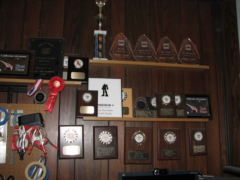
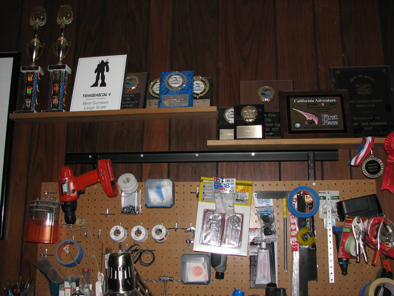
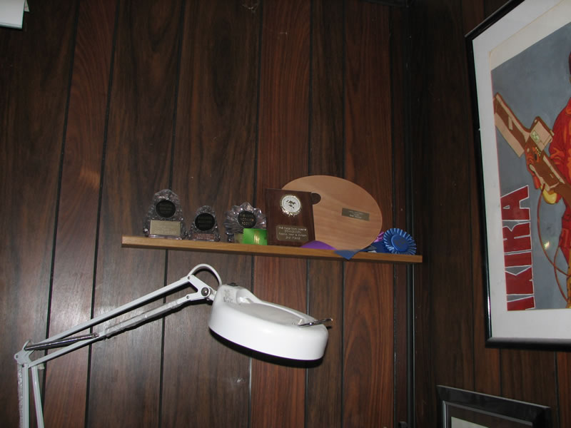
November 24, 2008: a friend had once asked if I ever got anything from the contests I’ve entered… here’s that answer:
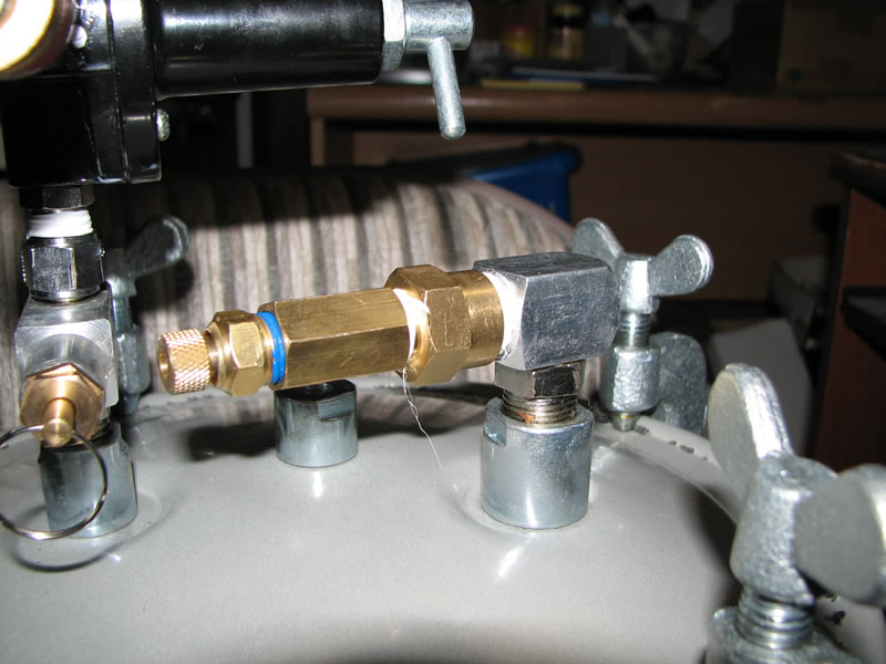
May 17, 2009: Here are the steps done to convert a paint pressure pot to a resin casting pressure pot.The first picture is the complete setup. The pot has a metal tube that runs down the pot for extracting paint. I just cut the tube out with a pipe cutting tool.
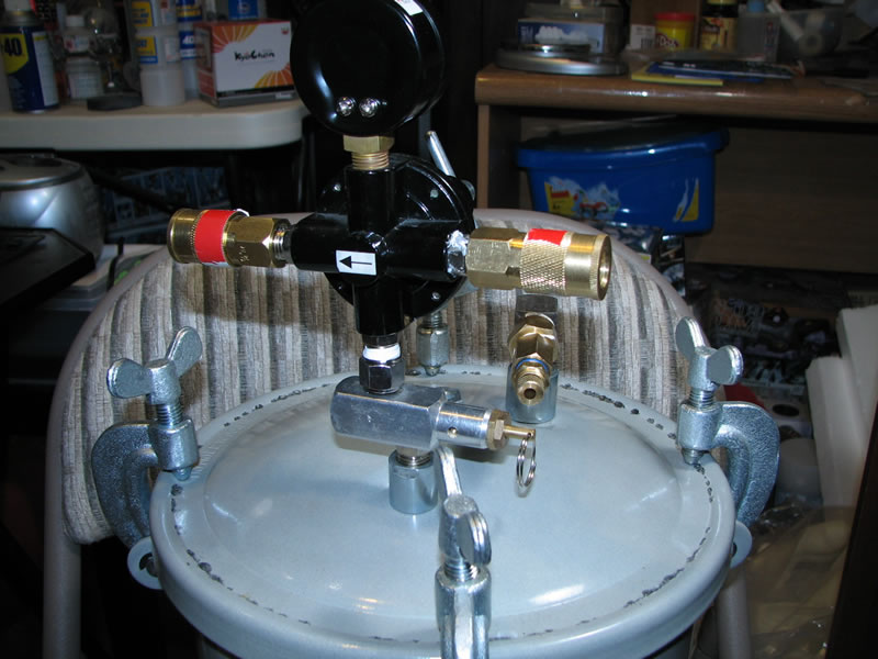
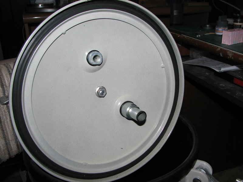
Next I plugged up the exterior end of where the metal tube is attached. The connection end is a 3/8″ pneumatic male connection.Since I wanted to use a drain valve, I needed to get an adapter fitting from 3/8″ to 1/4″. From there I have a coupler for the drain valve.
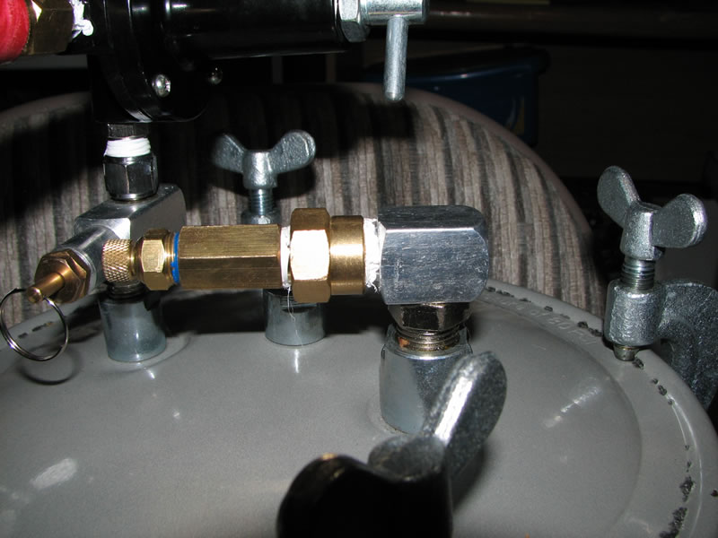
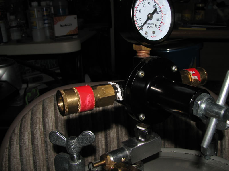
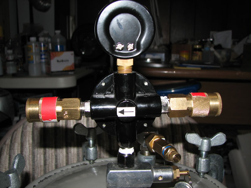
Next up, is the regulator/guage setup. I plugged both ends with quick connect female ends. These are both 1/4″ fittings. I can thenconnect from the compressor to one of these ends, and with everything plugged up tightly, I can start pressure casting.

your work place for gundam or gunpla is really cool everything is so expansive three airbrush nice such a cool place i thing you live in jap nice