This is an update to a page that is easily at least 6 years old. This page will include that information at the VERY end of, as over the years and more recently, I’ve found better ways for implementing the LED installation into your every day gunpla. In this tutorial will be the Gouf Custom mono eye, the HGUC Sazabi lighting, and then the original Gogg lighting tutorial written so damn long ago.
Gouf Custom
In comparison to the original LED modification this time around, as opposed to having all sorts of wires running through the kit, using a fairly sizable switch assembly, a big battery holder and battery assembly; I’m going small scale. Below is a list of the components I will be using for this modification:
- 3mm Red LED rated at 1.85 forward Volt at 10mA
- 150 ohm resistor
- Small reed switch
- SR521 watch batteries that put out 1.55 Volts each
- A rare earth magnet
And here is a picture of the above mentioned parts:
The idea here is to keep the components as small as possible so as to fit within the confines of the head assembly. The reed switch is a magnetic switch. It is basically two leads piped into a glass tube, so when placing a magnet over the leads or over the glass the leads connect and a connection is formed. It’s pretty damn cool, and these switches were about a buck a piece, so this beats the hell out of building my own magnetic switch or just using your standard mechanical switch.
The resistor is calculated out according to my power source and the LED’s specs. It’s pretty basic math: resistor (R) = (Power Supply Voltage – LED’s forward Voltage)/LED’s current rating. OR you can just cheat and use an online LED calculator. So with what I have, I need to use a 150 ohm resistor. First things first, connecting all the components and just doing a quick test.
The pictures are not the best representation of the assembly in action, so I made a quick little video to demo the entire test assembly:
Get the Flash Player to see this player.
Next up is to modify the head and internals so that everything fits into place. The mono eye holder is cut and sanded, then two small holes are drilled to accommodate the LED anode and cathode. The LED assembly is test fitted, which resulted in the need to further grind down the mono eye holder. About a third of the part was sanded away. This was the only part that required significant modifications, and it was just trimming down the part by sanding it down and drilling holes.
Looking back at the Gogg, just keeping the LED alone is kinda tacky as it’s just one long bulb; so to make it look more mono-eye like, a metal collar is added. Even with the small mono eye window, this small amount of detail is still fairly clear, and should still be visible once the mono eye lights up.
With the LED bulb in place I can now focus on the rest of the electronic components. The batteries are wrapped with duct tape and placed in series so that I get a total output of 3.1 volts. 1.55 volts in the single battery cell isn’t enough power to light up the 1.85 volt LED. The internal section of the head at the back is an open space and perfect for fitting most of the electronics. A bit of resin carving and shaving was needed to get the battery pack to fit just right and have the top half of the head come down.
The reed switch, as small as it is, wasn’t small enough to fit inside the head assembly, so a modification to the bottom of the neck piece was needed. A concave cavity was carved out of the bottom that fit the reed switch. The leads were then carefully bent. Side note: the reed switches are fairly delicate, while I was bending my first reed switch, the glass broke causing the entire switch to come apart. The leads are positioned to run up the back of the back corners of the neck and through bottom of the head. The only issue I have is that the switch leads are exposed and run up the side of the neck, but this is an easy fix with some mesh tubing, it’ll even look like a small bit of added detailing.
The bottom of the head piece was carved to open up room for the switch leads. One switch lead connects to the negative end of the battery pack. The resistor is soldered to the other end of the reed switch and then bent to fit. The resistor is then connected to the cathode end of the LED with the anode end of the LED connecting to the positive end of the battery pack completing the circuit.
After some fiddling with the fit of all the components to get all the connections set; everything came together quite well. And placing a magnet at the bottom of the neck assembly turns on the LED. The entire assembly resides within the head and neck and operating the LED only requires placing a magnet at the bottom of the neck. A definite improvement upon the previous LED tutorial.
And now for the pictures of the completed assembly.
And of course, a quick little video demonstrating the working assembly:
Get the Flash Player to see this player.
HGUC Sazabi
Starting with the leg thrusters for the HGUC Saz, some time was spent with drilling through the thrusters, test fitting, and more drilling. I wire wrapped four of the 3mm white LEDs together in parallel, then after successful test fitting, I assembled everything together.
Not too bad of a lighting job. Good thing that the Sazabi is a fairly sizable suit or this would be a really difficult job.
The legs’ wiring is threaded up the legs. Since I’m using some very high gauge wire, it’s pretty easy to thread the wires to where I’ll have my central battery and switch unit. Additionally, I did some mods to the bottom of the foot and added a thruster bell as well as LEDs there too.
At this point the Saz is up to 11 LED, 5 for each leg, and the backpack thruster. The side skirts were also lit up, so that’s three on each side bringing the total to 17 LEDs. These LEDs were added in the same manner as the leg LEDs. The Saz has an internal shoulder thruster that I added, and this thruster also has an LED inside. Saz is up to 19 LEDs.
The jumble of wiring I have for the kit so far. Fun times.
On to the mono eye. The space in the Saz’s head is small, but with proper planning, anything can be done. Starting with all the components of the head and the LED. For this, I’m using a 1.8 mm green LED as the Saz’s mono eye is green in color according to the anime. The LED is bent to fit into the area and the mono eye piece is modified with a metal collar replacing the original plastic nub. The ring piece is drilled through from the metal collar so that when the light is placed inside, the ring will move and still get light, keeping the functionality of the original kit’s design. A bit of the male section that connects to the mono eye ring is cleared. And the light is installed.
Temporarily, I used some sticky tack to cover the back part of the LED that I don’t want shining through when lit. The top piece of the head is cut internally to accommodate the LED. And with everything trimmed down, it all fits together fairly nicely.
A fairly simple modification, but took a little bit of time figuring it out and excuting the mod. LED count:20.
Next up are the two smaller backpack thrusters. I used the 1.8mm white LEDs and cut the contact point open so that the back of the LED can be inserted into the backpack. The thruster bells are just temporarily tacked into place. The back area will need some fine tuning to make everything flush and hide the extra lighting bits.
On to lighting the arm thrusters. First, I cast the arm’s thrusters bell section. The 1.8mm LEDs are glued to the resin cast bells with CA glue. Then the entire assembly is placed into the mold I made of the Saz’s arm thruster assembly.
So now I have a casted part of the Saz’s internal thruster component, with LEDs embedded. And a quick test has the lit up thrusters.
With the casted LED working, I went back to refine the process and made a new mold of the original thruster piece and cast new versions of the part that are much cleaner and easier to integrate. Now I can fully get on with integrating them.
The integration involves hiding the wiring as best I can. The shoulder insert piece that I made a few weeks ago also needs some detail so time to kill two birds with one stone. Using some wave parts, I created some ports. These ports were then glued onto the created shoulder parts.I coiled up some springs and sleeved them over the wires and then threaded the wires through the ports and into the shoulder area.
Here’s a test fit and test lighting. And with three lights on each arm, the total LED count is 28.
The current date of this page update is February 9, 2011 – the HGUC Sazabi project is still ongoing so this page will be updated once the project is completed to show the final lighting results.
MG Gogg
This is the original tutorial for installing an LED unit.
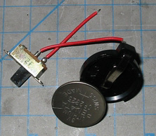
Since the MG Gogg is a relatively new kit, there does not exist a HY2M kit for it. The back of the Gogg has an incredible amount of room, that I thought would be perfect for storage of a battery unit and a switch for an LED assembly. The tools required for this are some wire cutters and a soldering iron. Parts used include a red LED, wiring, 3volt Lithium battery, and a battery holder. All these parts can be found readily at local electronics stores or your local Radio Shack. The following pictures is the LED I used.

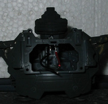
First, a few holes were drilled into the head of the Gogg, to allow room for the LED leads. Here are some pictures of the Gogg head. The first picture is the Gogg head upside down. The next picture is the underside of the Gogg head. The following two pictures show the LED inside the head. MG’s are great in the sense that these LED’s fit perfectly. If the LED is too big or not the correct shape, they can be sanded down, But do not expose the internal wires, this will ruin the LED, so if you are sanding the LED, be careful.
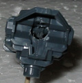
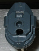
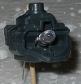
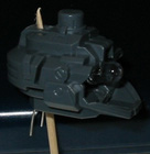
The following pictures are of the wiring, battery unit, and switch. The LED has a positive and negative lead. Using the battery, test this and find out which lead is what, and wire accordingly. I used red for positive and black for negative. I soldered the wires to the LED first, because it made it easier for me to solder the battery unit and switch assembly with the most ease.
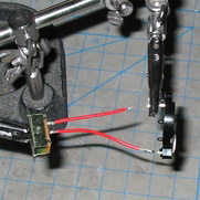
The first picture is the switch, battery holder, and battery. The second picture shows the LED with wires attached. The third picture is a picture of the switch being soldered to the battery holder.
The switch has two leads, to this I soldered red wire’s because only the positive current flow need to be attached to the switch. One wire is then soldered to the positive lead of the battery holder, and the other wire is soldered to the positive lead on the LED. The negative wire is connected directly from the negative lead on the LED to the negative lead on the battery holder.
The following pictures show the completed process, with the LED in the head, and completely connected to the battery and switch assembly. As seen, the negative connection is direct between the negative lead on the LED and the negative lead on the battery holder. The switch sits between the positive LED lead and the positive battery hold lead.
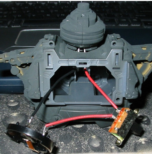
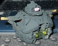
The following pictures show the LED as it is working as well as how the entire assembly fits inside the back of the Gogg.
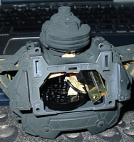
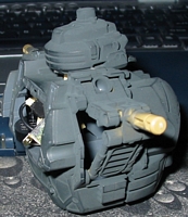
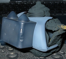
The following picture shows the LED switched on, and the installation is completed. It is a fairly simple process, just be careful with use of the soldering iron and it is best to have everything planned out before any implementation.
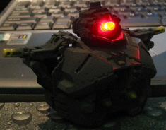


I was just wondering if you could possibly give me some advice on this, I want to install this mod into my HGUC Hy-Gogg. Just any advice would really help. Thank you!
The HGUC gogg head is fairly large in comparison to other hguc kits, so it should be fairly easy to install an LED. I recommend following the method used for the gouf conversion kit above. There are a hundred different ways to add lighting to kits, I have a few illustrated above.
The only advice I have is to just experiment with it, follow one the instruction style above. and if you get stuck, ask a question. Take pictures along the way to make it easier for folks to help you with any problems. Read the diagramming link, buy some leds a battery and some wiring and just try it out.
Can you give me advise or tutorial on how to install led lights on the HG try bbg and regular bbg on their clear parts?
I built a Bearguy and added lights to the eyes: http://gamerabaenre.com/bearguy_prog.htm So hopefully that will help you. It is not difficult, just need some practice working with LEDs.
Could you give me some advise. I’m planning to mod the HGUC NZ-666 Kshatriya I don’t know will it work or not since the parts look quite small.
The 1/144 Kshatriya is bigger than the 1/144 Sazabi, and I was able to light the 1/144 Sazabi: http://gamerabaenre.com/?page_id=1307 So it should be do able. You just need to look at where you’re planning on placing your lights and execute it. I would also need some more specific questions to better help you out.
I am a total newbie when it comes to LEDs… I messed up the wiring in my Perfect Grade Wing Zero Custom, and I’m wondering if it’s even possible to salvage the wiring for the chest and eyes.
Anything is fixable. It depends if you are trying to fix the actual bandai light units, or fixing the wiring scheme you custom made. I have not built the PG Wing Zero, so I do not know the wiring scheme (if any) there is in the stock kit. Pictures will help!
what size drill bits did you use to drill through the gouf eye piece?
I don’t remember the exact size, but it was pretty damn small. I have a drill bit set for model building and looks similar to this: https://www.ebay.com/i/280747113869?chn=ps I only needed the hole to be big enough to thread the LED leads through the eye piece. I suggest you get some calipers for measureing and then you can measure pretty close to what sizes you need once you pick up a similar bit set.