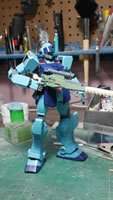
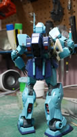
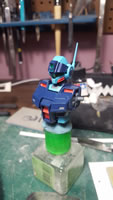
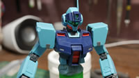
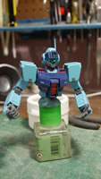
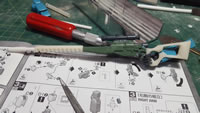
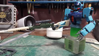
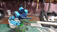
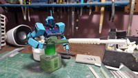
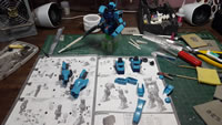
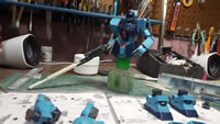
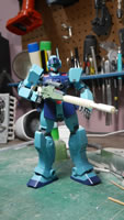
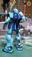
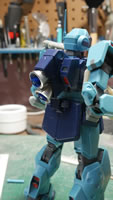
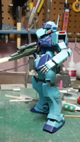
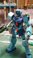
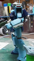
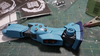
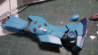
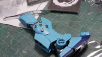
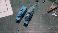
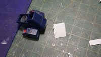
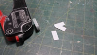
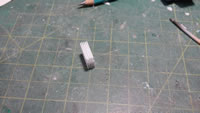
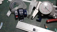
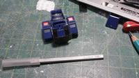
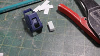
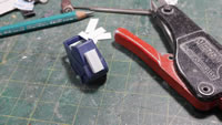
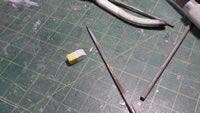
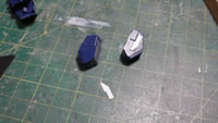
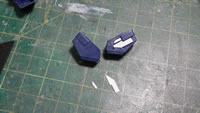
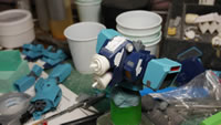
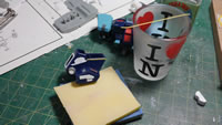
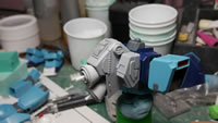
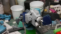
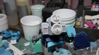
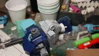
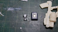
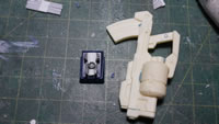
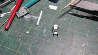
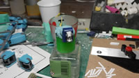
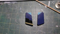
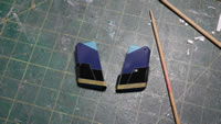
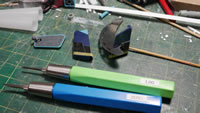
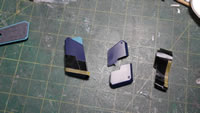
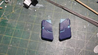
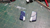
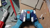
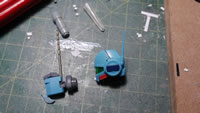
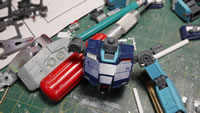
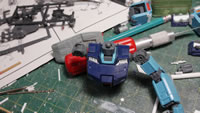
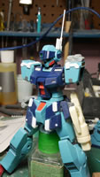
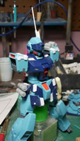
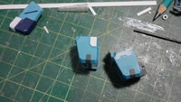
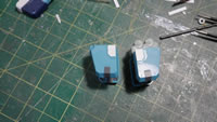
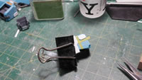
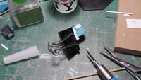
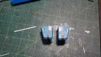
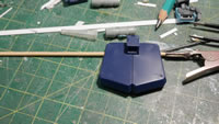
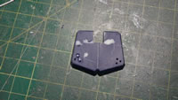
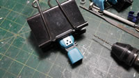
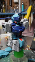
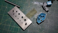
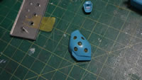
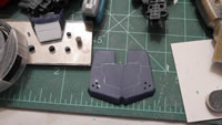
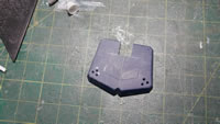
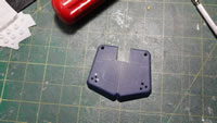
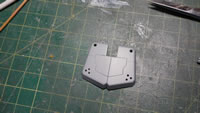
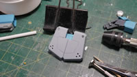
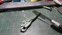
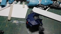
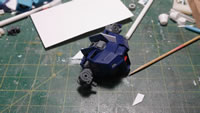
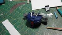
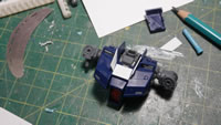
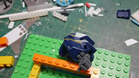
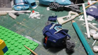
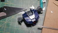
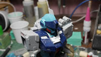
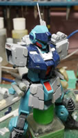
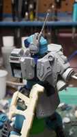
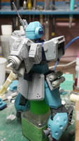
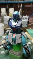
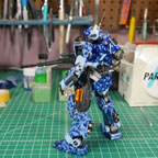
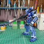
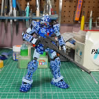
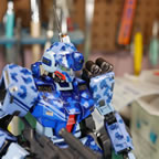
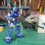
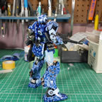
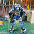
January 31, 2017: What better way to start off a new year than with a brand spanking newly released Master Grade GM Sniper 2 kit? Even better is that I have the motivation and some ideas bouncing around in my head for the kit. It was released about 2 weeks ago and I got the kit late last week. The little free time I had was spent cutting, sanding, and snapping the kit together. I didn’t finish the snapping process until last night, 1/30/2017.
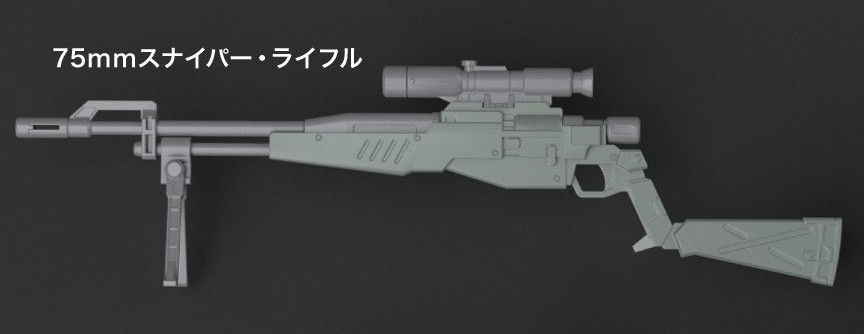
It is a cool looking kit and came together well. I have some reservation on frame made of abs like plastic. I’m going to have to be careful when I paint to keep from making the frame too brittle. As cool as the kit is stock, it will definitely need some customization. First and foremost, that God awful sniper rifle will need to be updated.
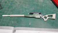
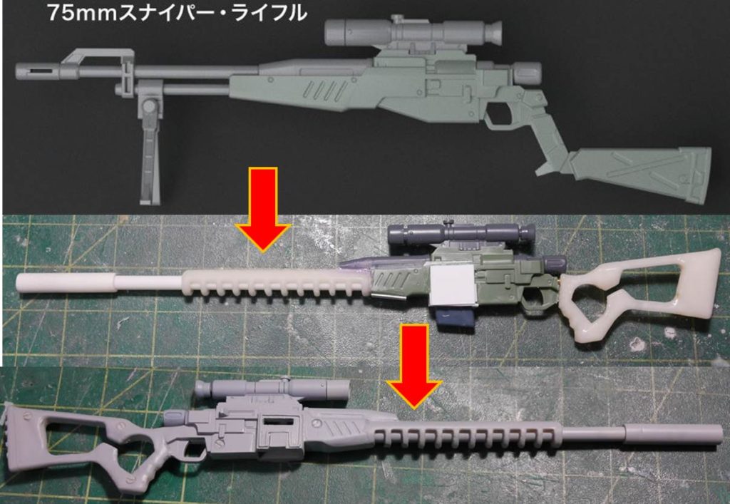
Prior to the kit’s arrival, I had already started the process for updating the rifle. I found a damn cool looking sniper rifle online from Fall Out Las Vegas.
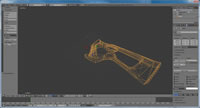
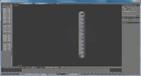
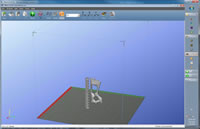
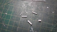
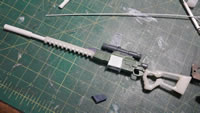
Everything starts with Blender; the free 3D rendering software I used to create new parts for the kit. A new stock and a new barrel is drawn, then saved off as stereolithography files (STL), and then sent to my Afinia H479 3D printer using ABS for creation. Since I didn’t have the kit on hand yet when I was drawing out the new barrel and stock, I just guessed and printed a rough estimate.
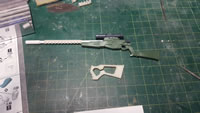
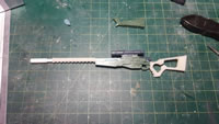
The kit arrived and I couldn’t wait to test out the printed parts. The fit was pretty decent. I’m actually quite surprised. But it is still a rough mock up. I just wanted to get a quick look and feel for the rifle. I think this is a marked improvement over the original design. I was never a fan of that oddly bent rifle stock for the original weapon. After looking at the mockup for a while, I felt that the barrel was a little too small. So I edited the blender file and printed a new barrel. The print was only slightly larger, but I think visually, the bigger barrel looks better.
On to cutting, sanding, and snapping. In the past, I’ve just cut and snapped the kit together and worried about sanding when I took the kit apart for mods or cleanup. In recent kits, I’ve discovered that I missed some clean up areas. So this time around, I sanded as I cut and snapped.
But back to the project. Cut, sand, snap, and repeat. I find that getting the entire kit together gives me a better opportunity to visualize some of the mod ideas bouncing around in my head. It also gives me the chance to take some before the mods type of pictures.
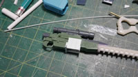
Granted, I’ve already jumped the gun so to speak and started cutting up the stock rifle. But that damn thing is so ugly that it seriously needed that attention so that I could focus on the important parts, the actual kit. Once I got the arm and hands assembled, I could mate the rifle and the arm together to see how much more I will need to modify. To my surprise, I only had very little to modify. The hands have a plastic slot that slides into the stock rifle’s grip. Since the new grip doesn’t have this slot, that needed to be removed. The printed grip was slightly bigger, so I sanded down the insides for the hand to get a good fit. And that’s all the modification to the hands I needed. Not too shabby. The new stock doesn’t look too big or too small, and everything fits perfectly. A few different poses and it all still work as designed. I’ve posted the progress so far on a few FB pages as well as reddit and got some inquiries for selling these mod parts for folks that also don’t care for the standard GM Sniper 2’s rifle. I will need to finish the mods and clean up these parts before I can make a mold and make casts. If folks are interested, that pretty damn cool too.
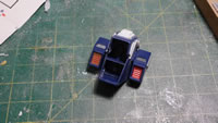
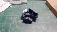
Last night saw the last bit of work for cutting, sanding and snapping. The legs and the backpack pieces came together.
Now that I have my completely snapped kit and take the “before” pictures. The real mess can surface.
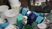
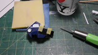
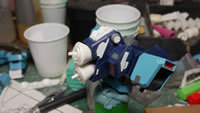
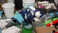
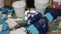
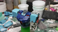
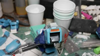
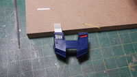
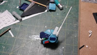
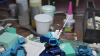
The first small mod is to beef up the backpack thrusters. I have some metal thrusters so I started playing around with a few different configuration options. The below pictures are still in the middle of that decision tree through bubble. But the rough idea is there.
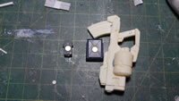
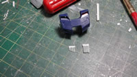
Next up, I took some parts from a GM Spartan conversion kit and started to add those to the left shoulder, the waist armor, and the left arm. There will be some further refinement, but this is a pretty good starting point for slapping on things to the rather plain looking sniper.
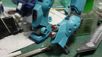
Next up are some metal details for the leg parts. There is some detail in the stock plastic, but I want something that stands out a little more, so I have these 3mm 2 part detail bits. I will be doing the outer calves with these metal accents.
I used a smaller 1.5mm 2 part metal accent piece for the elbow cover part. I drilled into the elbow parts a bitso that I can inset these metal pieces slightly.
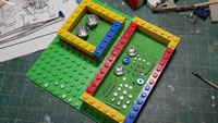
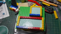
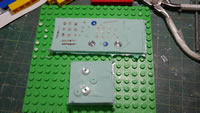
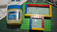
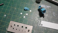
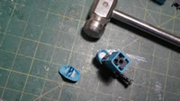
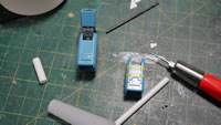
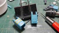
Since I have a limited supply for the metal accent pieces, I don’t need to actually use them since I can make a mold and have resin copies made. The resin copies will be lighter and easier to paint. I’m also making copies of the backpack thruster pieces now that I settled on a specific thruster configuration. Here’s the first step in the molding process; making the first of a 2 part mold. A box build with legos, some play dough as a base layer, the parts, then pour in the mixed silicone and throw the entire assembly into the pressure pot to cure.
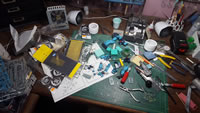
As usual, the nice and clean workbench becomes a complete disaster area during the modification phase. This is where all the real work starts happening. Motivation is still pretty high, and there are still so many ideas that need to make their way onto the bare Bandai plastic.
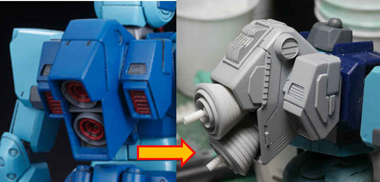
Feburary 13, 2017: I went almost a week without doing much work other than molding and casting the metal thrusters. They look cool, but are a pain in the ass to paint and they add a bit too much weight in comparison to a resin copy. Plus, they can get expensive if I keep buying and using them. So going back to my Chinese roots as a cheap fuck, I pirate the crap out of them. Then again, I’m not selling them, I’m just making copies to maximize their value. That said, I started working on the backpack sometime last week. I’ve seen some folks create these heatsink/vent things that look pretty damn cool; and some folks on reddit have asked how they’re done. So after a little bit of research, I figured out one way I could do them. For the quick and dirty, here’s a before and after for the backpack:
Briefly from where I last left off, I was making molds of the metal thrusters. I’ve gotten used to making two part molds, so here is the second molding after making the first part. Vaseline is used as an agent to keep the silicone from sticking to itself. Once the second mold is made, the metal masters are removed and put away. Some mold release is sprayed into the molds and the molds go into an oven set to about 100 degrees F to warm them up and activate the mold release. The stuff needs heat activate. Once all that is done, it’s on to casting the thruster pieces.
I wanted some massive thrusters to the back of the Sniper. It makes no sense since a sniper’s job should be to stay hidden, not generate a giant heat signature from oversized thrusters. But then again, it’s a giant robot – who cares if it makes any sense. I’m doing the same for the leg thrusters. I have those thruster pieces being molded and cast during all this.
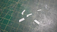
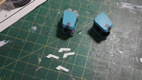
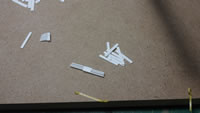
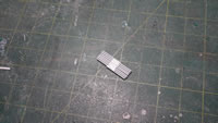
But now on to the real fun, making some heatsinks. I used strips of .5mm thick styrene. I just cut them to roughly equal size and started gluing the ends together to create a basic dual vent piece. Nothing fancy, just styrene glue and strips of plastic. Clamping down caused the strips to warp, so I just pressed them together firmly and left it alone.
With my vent block created. I needed to find somewhere to put the vent. Since I’m adding some massive thruster bells to the backpack it would make sense that there needs to be some sort of heat dissipation help. The caliper is used to measure out a rough area on the backpack. Dynamo labeling tape is cut and placed into position so I have a guide for cutting out a hole. Having the area scribed out, I used the scribed lines to help cut out the plastic, then metal files to get everything sanded down as well as squared up. The vent block is added into the hole as a test fit.
With the hole cut, I can focus on the vent block. I could have pre cut the final shape of the vent block strips, then glued them together to get the final part – but for this, I decided to work with the whole vent block. The idea here is to take a square block and start sanding to get a final sculpt. It is just a matter of preference in how to do this. I took some tamiya masking tape and used that as a guide for some initial cuts into the vent block. Slowly sanding with metal files, I started to create a slope on the top area and an in cut just below that, followed by a rounded end. This could be cool if I turned the 3D printer into a laser cutter and just cut out the shapes and glued them together. The silhouette curio would have been another good option for doing this kind of precision work.
Once that was done, the heat sink was put back into the hole for a test fit and look. I cut some corrugated styrene to add some detail to the sides of the backpack center piece. I also used some wave round detail parts to the circular indented plastic detail on the original part. Inside the wave round molds I added some corrugated styrene that I cut using a hole punch set. Another trapezoidal strip of plastic is cut and added to finish the center backpack block.
I sanded down the red square vent pieces that fit inside the backpack side sections so that I can add in some metal mesh material. I picked up this stuff from my local railroad hobby shop. These places are perfect for getting all sorts of scratch building and modding materials. I get my styrene strips, tubes, plates, etc as well as mesh and diorama materials from these shops. Next up, I cut more strips of styrene and just glued them to the side of the backpack sections. Once the glue dries, some light sanding is needed to smooth everything out and get the part ready for priming.
With another test fit, there’s still something lacking. So more masking tape is brought out as well as the dynamo tape. Using different width thickness of the masking tape helps keep things uniform when laying out the heavier dynamo tape that will be the actual guide the scribers run along. This makes it more precise than eyeballing it or trying to lay down a ruler and pencil in guidelines. Using a 1mm scriber, I cut in a fat line that I will fill partially with some 1mm styrene blocks. A zero scriber is used to make some new panel lines from the bottom of the circular vent detail to the thicker line.
It is important to always continue to test fit. Checking sizes, checking the look and feel. But it will always look like a mess of different colored plastic and no real uniformity until it is primed. The glue marks are sanded down, some of the rough edges are sanded. It’s not fine tune sanding, but enough that the primer should stick and visually help focus the fine tune sanding areas.
The backpack is taken apart and primed with Mr surface 1000. Mr resin surfacer for the resin parts. I recently discovered that they no longer make Mr Resin Surface and it’s just called Mr Primer Surfacer. So I have a few bottles of that stuff that I’ll test out. I have found that Mr resin surfacer doesn’t stick too well to plastic, so hopefully the Mr Primer Surfacer will fix that issue as well as stick nicely to resin. But we’ll have to wait until I exhaust the resin surfacer, which will be soon. Once primed, and left to dry; the parts are assembled and it’s starting to look like a single piece instead of a frankenstein mishmash of resin, plastic bits and metal mesh.
The backpack is pretty much done – I still may do some things but it’s close. Time to move on to the other body parts. First up is the shoulder. I was originally using the GM Spartan conversion kit’s shoulder mounted beam saber detail – but found that it was too large for what I wanted. Here’s what it looked like from the first post about this project:
So I swapped it out with what I was using as the waist skirt detail piece. I think the smaller canisters work better here for what my plans. Some corrugated plastic detail for the bottom of the part as well as more mesh over the existing vent. I cut out strips of styrene to add more details to the shoulder. I’m still working on this as I’ve kind of come to a block on what I want to do with the big dopey looking shoulders.
On to the chest pieces. I decided against doing the mesh over the upper chest vents and I figured I could replace them with some more heat sink style vents. Same as before, cut strip and glue them together. Here is a quick test fit. The glue hasn’t set on the assembled styrene vent block so I couldn’t get into sanding and sculpting the final shape for the vents. But this is a pretty good idea.
Since I took away one of the side skirt details, I felt the need to replace it with something. Snipers typically carry an SMG or smaller close combat weapon. I don’t care for the 90mm GM Machine gun – so into the parts drawer and out we get an ore gun. I now also need to create a holster of some sort to hold the ore gun. In the box of spare parts I find a piece that looks like it would be a good base part to start building this holster. U clear out the middle and sand down the edges so that the ore gun’s handle fits. Now it’s time to figure out out to mount everything. Magnets. Rare earth, neodymium magnets to be specific. One side goes into the ore gun’s handle, and the other is build into the holster. The holster is detailed with a few round molds from the wave option parts set; a cut styrene tube for the bottom half, two small styrene rods along the inner edges of the top half followed by a strip of corrugated styrene to tie it all together. The back of the part is drilled and a relatively thin magnet is glued into place. This magnet will hold the ore gun but is not very strong. The original waist detail is drilled out and a thicker magnet is added here, and the combined strength of the two magnets is a very strong hold for the ore gun.
Here’s everything assembled for a test fit and the ore gun is being held up nicely.
Going back to the other side of the skirt, I did not want to use the same detail piece that I had for the shoulder, so I ended up cutting up my original shoulder detail piece to shorten everything and created some detailing for the other skirt side. The side skirts are mostly done.
There is so much more work that I want to put into this kit. So I’m scouring the internets and looking for inspiration. But the project is coming along. The nice thing is that since there is still so much to do; if I get modeler’s block on a particular section, I can put it aside and focus on a different section. This kinda makes it hard to do decent updates as it’s scattered here and there. But that just means I will just have to wait while I get at least 90% of a part done before posting an update. A good thing that there is a build gathering coming up this weekend so I can get some live feedback that may help jump start, or just add more work to the list of to dos.
Feb 20, 2017: This is going to be a fairly sizable update. This includes the work from last week as well as over the weekend. I’m starting to focus and get more and more work done as the inspiration continues. The front skirts are REALLY plain looking. Yes, it’s a grunt suit, so it should be relatively simplistic cannon fodder that all GMs aspire to be; but it’s just plastic, so what’s better than cutting the plastic and then gluing more plastic to the cut plastic? There are still some scattered bits of work here and there as is typical with this kind of build. While glue or putty is drying, the focus on other sections keeps the work going. All the while, I’m taking pictures of all the progress.
Starting off with the skirts. Yes, they’re plain, and that open space is just screaming to get some detailing.
The first step is to plan out the design. I use dymo tape since it is fairly thick and works well as a guide for scribing tools or saws. The first line is laid and I align the tape against the bottom of the skirt. This way, I know how to line this up on the other skirt piece. Once I have the first layer of dymo tape, I laid down a thin piece of masking tape as a second guide. I cut the next layer of dymo tape at 60 degrees and laid it down using the masking tape as guide. Now I have the first level of design done; I made the mirror image for the other side.
The scribing tools are used to make groove lines. Once I have the guidelines in; the thin hobby saws come out and I start to cut the pieces from the sides of the part inward towards the middle. The middle will be difficult to cut with the saw, so the saw is not used to cut this area. I scribe the middle line a few times to thin down the plastic then take a hobby knife to press in and break the line. Since the plastic is fairly thin, I can snap the part and get a fairly clean break. Sanding the edges cleans up the rough edges from the cutting as well as creates a separation line between the two cut pieces. One horizontal side is sanded to remove more plastic than the other edges to create a wider gap.
Most of the cutting work is done with the hobby saws and the detail work is done with a metal file to sand down the edges. Here’s what the skirt looks like assembled. Breaking apart the skirt adds a nice bit detail to the plain surface.
Next up, I want to remove even more plastic, so again, some guide masking tape is placed, followed by the dymo tape.
The scriber is used to channel out a guideline. Saws are then used to cut away the excess plastic, files to clean up the rough edges, then once assembled, the design is starting form.
Some cut strips of styrene glued to the surface adds another layer of detail. The raised detail gives some added depth to the skirts. The last bit was to drill out a hole for a resin minus detail piece.
Next up, I decided that the original antenna just didn’t look good. The clippers went to work *snip* *snip*, and off it came. I have some pieces of styrene, an I-beam, styrene rectangles, strips, rods, and tubes of different sizes. It’s a matter of cutting and gluing to create the new antenna. I had to let the glue set up before continuing to add little details.
Small details round out the rest of the antenna. A resin minus detail, a metal collar piece, another resin collar piece and some magnet wire wrapped around the smallest antenna piece finish everything up.
The antenna build was quite easy and if I didn’t wait for the glue to set up, can be done relatively quickly. Here’s a video I made of that process:
It should take you about 20 minutes of actual building time. You really should wait for the glue to cure for each step however and enjoy the build! Moving on, I did some vent work for the upper torso vents. Same process with the backpack heatsink; glue strips of plastic together, then sand it down to sculpt the final look.
This catches us up with the second half of last week. At this point, I assembled the modded parts to get a look and feel for things. It is easier to visualize the mods after a layer of primer, but I’m still working on things so this is a good quick visual before continuing.
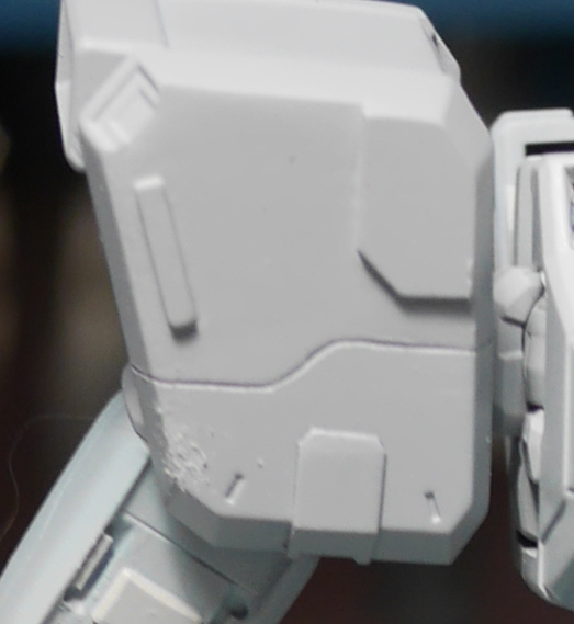
After mulling about the pla plating on the shoulders. I didn’t know where I was going, and it wasn’t looking good to me. So I took out the sanded and effectively erased the plating that was glued on the shoulders.
I cut out some smaller bits of plastic this time. I visualized that the shoulders would look better with minimal plating over what I was originally trying to do. It’s only plastic, so if you add too much, you can easily take it away. If you take away too much, you can always add it back. It really is just labor. Building models is fun! Right?
Once the new styrene pieces are glued. I used some masking tape as guides and using a template I created from a strip of plastic. Placed it along the guides and held it down with a paper clip, and scribed some new lines. I have four sides to scribe, and since they were all the same piece effectively – a template would make things work faster. The last thing was to add a small sliver of styrene to the edges of the shoulder. This adds a little more depth with the raised detail.
Returning to the last part of the waist, I figured I’d do some scribing on the back skirts as well as add some drilled out holes. In the next picture, you can see some dissolved putty on the part because I screwed up on the scribing. You can see two sets of holes too. One that is done decently, and another not so – the left side. I ended up having to fill in the holes with styrene rods. The lesson here is that you do not need to worry about screwing up. Because you will. Accept it and get to work fixing it when it does happen. I believe if you ask any model builder, there’s a decent amount of time spent fixing mistakes for any kit they build.
Looking at the picture, how did I get the right side looking decent while screwing up the left? Templates. My first attempt, I eyeballed and freehanded the drilling and apparently I was also drunk. In the below example, I added the same tri-circle drilled out look to the arms. This time, I created a template. I took a strip of plastic, drew out a triangle, then drilled out some holes in the triangle to create a drilling template. Having a template helps make things more uniform. Especially if you’re reusing a detail effect in multiple places or even on mirrored parts. The left side of the skirt is still curing from the fixes, but I was able to test out the new template on the right side successfully.
Friday came around and I was at a point where I had a decent number of parts ready for the first layer of primer. Here’s what the kit looks like after priming the front and side skirts as well as the shoulders and the new antenna. Things are starting to come together and the mods are being tied together visually with the primer. There are still sanding mistakes and areas that need attention; but the uniform grey is a milestone accomplishment. Proof of progress so to speak.
The start of the weekend begins with the circle punch set. The elbow covers for the kit have an empty space that just begs for a little bit of detailing. Taking some corrugated plastic and the punch set. I cut some circle details and glued them into place and trimmed the excess. This is a small detail bit that is very easy to do.
The punch set is also used on some metal mesh to cut the meshing for the inner leg pieces. I drilled out the holes for the inner section of the legs and just glued the mesh to the insides. Yes, the mesh is facing different directions… things like this really mess with the OCD of fellow modelers. Fun things to do to your friends. But I may end up fixing this as I really haven’t started on the legs much.
Back to the rear skirts; since the putty has cured as well as the filled in hole. I templated the left side and drilled out some holes. I sanded down the dried putty and re-scribed the lines. This still looks very messy since you cannot tell where the clean lines are vs the filled mistake lines. I also drilled out the upper corners of the skirts for some minus detail bits.
Once primed, things start to look better. The bad holes have been filled as well as the bad lines. Adding in the metal minus detail is the last thing I did to this so far. I may still add some styrene, but look for that in the next update. I will probably add something – just not sure what.
Rifle work
Next, we return the to first thing I was modifying – even before I finished sanding and assembling the initial test fit for the kit. I cut down the main body of the rifle because it was just too damn long with the new barrel. The 3D printed piece along with the styrene barrel are glued into place. And I start work on building the lower section for the relocated magazine clip. Not much, but at least the rifle is starting to get some real work.
The inner arm pieces are masked off with some guide tape to scribe in a small detail line.
I have been mulling over what to do with the chest for a while and finally came up with an idea late Saturday night after the build gathering. I measured out some styrene strips and glued them to the collar and upper torso of the kit. This will be a frame of sorts for some detailing that I will add. The detail bit will be glued to plate of plastic sitting within the frame just below the neck.
Letting the glue set over night, I used some masking tape as a guide and trimmed down the 70’s era super collar. Some light sanding to shape and conform the part to the original collar, I can get to work on adding more details.
Again, I’m working with bits of styrene. I glued some thin strips together to create the three main components for the chest detail. For the middle piece; I glued two thin styrene strips with very thin strip in the middle to get a slight space between the two strips. The main plate is glued to the chest followed by the three detail pieces. Once the glue sets up, I can continue to sand down and sculpt out the details for this area.
Here’s what the kit looks like after all the weekend’s work. I still have the feet, the rest of the arms, and the legs that really haven’t saw much progress, yet.
Febuary 27, 2017: It’s Monday, time for the blog post that brings everyone up to speed on last week’s Sniper work. The main focus for this update will be the sniper rifle which I finally revisit after the very first post with a half-assed slapping of a new barrel and new stock onto the sucker. In the below picture, you can see that quite a bit of work has been done to transform the standard GM Sniper 2’s rifle to a one that the GM Sniper 2 would pick up in New Vegas.
Other than the rifle, I got some work done of the arms, started in on the feet, and got the upper half of the body primed.
I actually started working on the feet as one of the first mods to this project, but have been dragging my own feet on the damn process. The task is pretty slow since I need to glue layers of styrene, let that cure, then sand it down, then repeat the process with more styrene. The process is fairly laborious and boring. I have been holding off on posting about it for a while since I wanted something more substantial; or at the very least, something visually entertaining when I got around to this. But I’ve been stuck in the loop for this mod.
The real task comes when dealing with the correct proportions and getting the correct shape for both pieces. Granted, I could have cut the work in half by just building one foot, then making a mold of that part and casting it. Actually, that is still an option now that I may do since there is still the bottom detail that needs work. Great, now I’ve wasted my effort on an extra foot piece that I really didn’t need to do. It’s better to figure these things out now than later I guess. This should effectively pull me out of my loop that I’ve been trapped.
Ok, the real meat of this post starts here. Last week, we left off with attaching the new barrel to the chopped foregrip and gluing plastic plating around the midsection of the rifle’s lower receiver. Here, I’ve added a magazine and the stock and some plastic plating on the bottom of the foregrip to help build up the transition to the bottom of the new barrel piece.
The styrene plating that I slapped together is to create the lower magazine receiver. Once that cured, I did some rough sanding then drew out a box for an exhaust port for spend shell casings. Next, I drilled out some holes within this box. These are pilot holes that start the process of creating the exhaust port. The hobby knife is used to break the thin areas between the pilot holes and to get a rough edge going. Once there is enough space, I can start in with metal files and start shaping out the exhaust port.
The kit comes with a magazine for the Sniper’s SMG, but it wasn’t going to fit my needs; so I looked in my box of spare parts and found a tree from the GM Kai kit. The magazine for that kit’s machine gun was almost perfect. Almost because it was too thin on it’s own, so I glued the two halves to a few strips of styrene. I also had to cut the top of the magazine since it was too tall for my use as a low profile, low capacity magazine. Yes, I inserted the magazine backwards in the 4th picture. But I was really testing the functional gimmick of having this part removable. I did the same thing here as with the exhaust port. I drilled out some pilot holes, cut the excess walls between the pilot holes, then sanded away using metal files to clear out the area for the magazine. With the exhaust port exposed, I glued a round to the top of the magazine that I will detail up so when done, you should be able to see the round inside the exhaust port.
Cleaning up the lower receiver mods, the face of the magazine receiver needs some detailing. Thin strips of styrene is glued into position. Square and triangle pieces of styrene are also glued to finish the detailing. It looks messy, but once the glue cures, a metal file will help sculpt and straighten everything out.
The front of the gun is done, time to glue in the stock. Once the glue set for the stock and back of the rifle; light curing putty is used to fill and build up the transition areas. It is starting to come together, but it still looks like a frankensteinly mashed weapon.
The first priming session starts to really tie the rifle together. It also shows all the missed transition areas that need to be puttied and fixed as well as all the missed sanding areas. But it is definitely coming along and now looks so much different from the original weapon.
In the above picture, I didn’t prime the scope. When I primed the main rifle, I had just glued the two pieces of the scope together so that seam needed to cure up before sanding it down and priming. It was at this time that another idea popped into my head. I can modify the scope too.
I removed the front lens piece and replaced it with a piece of styrene tube that matched the diameter of the existing part. To this, I punched out some mesh and glued this to one end of the styrene tube. I cut another small length of styrene tube and glued this to the back of the mesh side so that I have a styrene tube with a piece of mesh in the middle. The male attachment point for the scope’s body will now be the new lens for the scope.
Now the question is why the hell did I add a piece of mesh to the lens? Well, in real world sniper scopes, you can get an anti-reflection scope cover. Suspension of disbelief is required. This is the Gundam world, and gunpla is freedom. There, all my bases are covered for why I did this now. Plus, it just looks damn cool, so there!
Next up, I focused on the stock. I glued some styrene strips to the back of the stock. Scribed a line. Then drilled out some holes and added some resin minus mold pieces as bolt piece for the stock. Cleaning up the styrene strips, the filled transition area fixes from the first priming session, and the scribed line; the rifle is primed again and everything is finally coming together.
Returning to the arms, I scribed a diagonal line and glued a strip of styrene to the upper arm pieces. The upper arm pieces have directionality to them – meaning, there is a front and back part if you are not careful, this can really fuck up your day. I’ve kind of learned my lesson about this in the past, so I marked the back areas just to make sure. I got to working on the front areas with some scribing and styrene strip addons.
I added some styrene to the forearms as well.
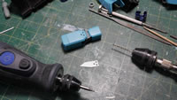
After sanding and shaping the styrene details for the forearms; I drilled a small pilot hole for more details. Once the pilot hole is punched out, the location of the hole is checked. Satisfied; a bigger drill bit is used to widen the hole. The last part is to use the dremel with a ball sanding bit to bevel the hole.
A resin minus mold piece is glued into position. After a few days, the upper arm detail didn’t look good to me, so I removed the diagonal styrene and filled the scribed line and started over. I replaced that detail with a simple straight line + diagonal + straight line detail. The arms are ready for primer.
Scope works part deux: since I did the rifle scope, I mind as well add the same bit to the head scope. Same deal, except on a thinner styrene tube that fit the sniper’s head optics area. I punched out a small mesh circle and glued this to the styrene tube, then glued it into place. I think the detail looks fairly decent.
The chest piece is roughly cleaned up and ready for priming too.
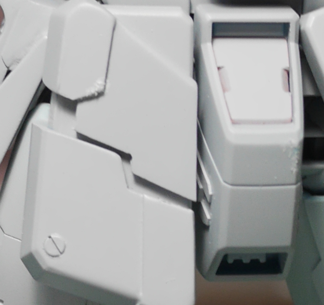
I finally get some more work on the legs. I want to do something similar to the skirts and cut up only one side of the calf area. So the same process is used. I measured and taped up the legs and scribed a guideline. Then hobby saws are used to cut inwards. A hobby knife and scribing is used to cut the diagonals and middle sections. And the metal files are used to clean up everything.
And of course. Things don’t working out quite so well. So here is an example of cutting away too much plastic or making a mistake and needing to fix it. I glued in some styrene to start rebuilding the mistake of cutting./sanding away too much plastic.
Frustrated with the legs, I glued the styrene fixes and moved onto something much more productive. Priming! Priming really ties all the mods together and I get a real look at the progress. I also get a real look at all the mistakes that will need to be fixed. The key is patience and imagining the bigger picture. Focusing too much on the small areas will trap you in a loop that you’ve never get out of or it’ll destroy your motivation and the project goes into development hell.
Here are some more angles for the primed upper half of the kit. I think I am already more than halfway done with the building and modding part of this project. The once a week major priming session really works to reboot the motivation.
Once the primer cures and I’m doing looking at the big picture; it’s time to focus back on the little details and get to fixing all the surface defects. Light curing putty comes in really handy since it allows for some really quick putty work. If I’m not in a rush, I will use dissolved putty or another other styrene based putties that take several hours to cure.
March 27, 2017: Finally getting back to work on this project. Taking a two week vacation really breaks the momentum I had going for this kit. I actually thought about bringing pieces of the thing with me to work on while I was in Tokyo and Hong Kong. Then, knowing my damn luck, I would have lost said pieces. So I just quit cold turkey and left everything here. Plus, I really didn’t have time to do any sort of model building while I was gone. Hell, I even got to catch up through the first half of Iron Blooded Orphans by marathoning it on my flight back as my attempt to reset my biological clock and fix the potential week long jet lag. It worked, I only ended up taking an hour long nap before landing back in LAX. Ok, enough digression. My trip to Tokyo and HK was quite fruitful. I ended up picking up a bunch of new tools that I immediately put into use. While in Hong Kong, I visited the Man 66 Hobby shop on the 7th floor of the Richmond Commercial Building in Mong Kok. I saw a damn cool cutting tool, “the Chopper II” which is an improvement on “the Chopper” that I had picked up a couple of months ago. So my first order of business when I got back was to order this via Amazon. It is pretty damn difficult to get back into building mode. So it took a few days. I didn’t quite know where to start; or actually, I wasn’t motivated enough to actually start. But over the last week, I started slow on a few pieces here and there. The majority of the work for this post is focused on the legs. We’ll start off with where I last left off.
So the last update on the project, I had cut up the outer calf parts. The problem is that the cut isn’t precise. So after sanding an opening, I needed to glue some plastic back into place to rebuild some of the screwed up areas. So this past week, I’ve been slowly adding more plastic, sanding it down, test fitting, then adding more plastic back, and resanding, etc. I also glued the two halves back together so that I have a solid connection on the ends. It seems counter intuitive to cut the part in half only to glue it back together, but it makes for a much easier process for this kind of a mod. The last picture in this series shows what it currently looks like. There is still some cleanup work; but I’m progressing. I also added some strips of styrene to the back of the thruster housing. I still need to sand and prep that bit of detail.
The real work actually started this weekend. I started on the calves but I really was still debating on how I wanted to detail the legs and I was just stuck. I wanted some details, but didn’t know how to go about it. My first try was to get a piece of plastic, cut it to the shape of the knee, then start drawing out where I wanted the cuts and actually cutting the plastic part. This didn’t look good at all.
One thing I learned from talking to Man from Man 66 Hobby was to cut the plastic into atomic shapes and then just glue them together. We were discussing the vent I had made for the backpack. I described my method, and he responded with his. I think I briefly talked about this in the interview above. But the jist of it was a different perspective and approach to solving the same problem. So I took his approach and reworked the idea of the knee details. I cut a basic strip of styrene and glued this down the middle of the knee. I then started cutting thinner strips to attach to the middle piece I had already glued into place. Using the cutter, I cut angles into the thinner strips, then just glued them in to position. It was quite easy, and the precision was much better than what I had started out trying.
The cutting tool helps with the correctly measured and correctly angled cuts. The plastic is just glued together and the excess is just trimmed away when the glue sets up.
Once the glue cures, the top and the sides are sanded down and then I can add more plastic. The tape and the strip of styrene are there for a guide for adding a parallel styrene detail.
Returning to the foot, I used the same technique and cut strips to create the indent detail. Once the glue sets I can go back and sand to clean up everything. I still have the bottom of the foot to detail however.
I had toyed with the idea of leaving the thigh pieces alone since the skirts cover most of the thighs. But after considering it, I started working by adding a strip of corrugated styrene on the outer sides of the thighs. While playing Gundam Battle Operation, I checked out some of the details in the GM designs, and got some inspiration for the back of the thighs. Some dynmo tape and the scribers went to work to cut in some details panel lines. For the front, there is already some minor details, so I only added a single scribe line and then did cut a 1mm scribe and glued a small strip of .5mm styrene to detail up the front side of the thighs.
The majority of this work was done this past weekend. I still need to go in and do some initial cleanup before I can even consider priming. But I think the details look fairly decent so far. Here’s what the legs look like now sans the feet as I’m still working on the toe piece.
The motivation is back and I’m glad it is back. These times are dangerous and in the past, kits have found their way back into the box.
April 6, 2017: I’ve continued to plug away at the kit as I got some new ideas flowing but still need to finish off the old ideas that I’ve already started. I also finalized the work on the new toe and will show the process of making resin copies. Since a majority of the build work is done; I also took some time and sprayed the initial layer of primer over the legs and other parts. At this point, it is about 90% primed. Here’s a quick teaser picture.
Going back a few weeks, I was actually working on getting a new visor. The clear green visor wasn’t cutting it for me and I wanted to use some aurora film with the visor but also keep some of the transparency – since there is quite a bit of detail work under the visor. The clear green messes with the aurora film, so I needed to make a mold and some resin copies. While doing this, I tried casting the clear resin with the aurora film. It didn’t work out at all. So I ended up just casting a clear piece that I will then just glue some aurora film over. For now, I have a clear visor piece.
Next, we return to the toe. The top part is sanded down and everything looks good. The bottom part is also sanded down leaving a completely blank area. I know that if this kit is standing on a base, there’s no way you can see any sort of detail. But I haven’t really decided on the final pose or how this will be displayed; so it’s best to just add in some new details. So here’s a comparison picture from the blank bottom of the toe to the detailed primed toe. Doesn’t look too bad.
Playing Gundam Battle Operation; I was looking at some of the suit designs on there and got some ideas for more details. For the lower part of the feet, I measured out and cut some dymo tape and scribed out a few 1mm cuts. I also did this to the toe piece.
To detail the bottom of the toe piece. I just glued some cut styrene strips. A priming session left me with a plain looking area even with the added styrene. So some details needed to be added to the styrene. I scribed cuts, some bevels, a few more lines, and drilled out the styrene to add in some punched out vents to finish the bottom toe details. Things are starting to come together and there are a few prime/sand/putty/prime sessions to finish up the toe and get it ready for duplication.
The crotch area needed some detailing, so I added some cut styrene here. Granted, once the skirts are on, all of this detail will be hidden, but if you look, you’ll still be able to see it. So again, depending on the final pose, this could be good, or a complete waste of effort.
The legs were done, so time for the first priming session to find all the areas that will need fixing. Because there will always be areas to fix. At this point, I have 90% of the kit primed. There are a few small bits here and there that still need work. Notice too that there’s only one toe. That’s because I only built one toe. I was originally working on both then realized that I was doubling the work for something that may not even match when I’m done. I want the toe to be identical. I am very far from a perfect builder, so there is no way I could build two toe pieces and have them even remotely identical. So I only built one.
It is good to see most of the kit primed. It is a significant milestone. The kit doesn’t look like a mishmash of parts and there is some uniformity. Now to take it all apart and get to fixing the problems that the primer found for me.
One of the parts that didn’t get primed yet are the ankle covers and front foot armor piece. The part needed to be glued together as there is a horrible seam down the sides. Once glued, I first attempted to add some details with the scriber. But after scribing one, I didn’t like how it came out I grabbed some dissolved putty and went to repairing the ugly scribing. I then just cut .1mm thick styrene strips and used this as the detail method. So instead of some scribed lines, I have a .1mm raised bit of detail.
Next bit of unprimed plastic is the beam saber. Since I added in a forearm saber holder, I need to modify the saber to actually look a little better when displayed in the holder. I drilled out to top part of the holder so I can glue in a metal collar piece. Then in the middle, I glued in a thin brass rod. The back of the saber was cut slightly to shorten the overall length and some magnets are added to the holder and beam saber handle to hold it all together. Now there is functionality to the beam saber and the new holster too.
Here’s what the arm/beam saber holster/beam saber assembly looks like now. Once primed, this should match up nicely.
Now that I’m satisfied with the toe piece. I can get to making copies. First step is to make the mold. My holding box is made from legos. And lining the bottom is playdough. The playdough works to hold the part in place while the silicone sets up. It also help when I make two part molds. I just find it easier to work with two part molds. The silicone I use is a shore weight of about 20. Mixed by weight at 1 part activator to 10 parts silicone and it is ready to pour over the master piece.
The mixed silicone is poured into the lego box with the toe piece sitting at the bottom. The cure time is a couple of hours. So this whole assembly goes into the pressure pot to help reduce bubbles.
Left to cure overnight. The next day the assembly is disassembled and I have a block of solid silicone rubber topped with playdough.
The playdough is removed and then the mold is washed to remove excess playdough and dried. The lego box is reassembled and the mold is placed inside with what was the top part, now sitting on the bottom. Before adding a new layer of freshly mixed silicone, I apply a small amount of vaseline around the part and half the mold. This keeps the mold from sticking together in areas I don’t want it to stick together. And when I’m done, this will make removing the part as well as removing casts much easier.
Here’s the next layer of freshly mixed silicone. And thrown into the pressure pot again to reduce bubbles.
Several hours later, the mold comes out of the lego box and the area where I applied the vaseline comes apart easily and I can remove the master piece. Now I have a mold to create an endless supply of modified toes.
I did not take pictures of mixing the urethane resin because my work time is VERY limited. However, what’s not shown is that the mold internals are sprayed with a mold release agent and the entire mold is placed into my workshop’s toaster oven set at about 90 degrees F to heat the mold and activate the release agent. Once that is done, I just mixed equal parts of the resin by weight, pour it into the mold – squeezing while doing so to help remove air bubbles that may get trapped in the undercuts of the mold. Then quickly placed into the pressure pot to remove as much air bubbles as possible.
And 15 minutes later, I have an exact copy. Granted it needs a little bit of sanding and some filling for a pinhole – but this beats trying to scratch build an exact copy.
Last but not least is a quick scratch build knife. Since I relocated one of the beam saber hilts to the forearm, I will not be using the rear skirt beam saber holder. Time to create a new weapon to put back there. Just using some cut styrene strips and glue, I get a rough shape. Once the glue sets up, I can start sanding and shaping the blade edges and get some general clean up work done. I also get to work on building a sheath for the knife that will replace the rear piece on the skirt. I used the same GM Spartan waist piece, but cut it to fit the knife’s width and glued it back together. I will be removing quite a bit of plastic then adding more details. So this is a good starting point for how rough something is at the beginning.
I have ideas for the paint scheme forming and I also have ideas for a base too. But I need to focus on getting this damn thing completely ready for painting to even bother considering the ten other steps I have down the road for this project. Motivation is still pretty high and I’m enjoying the hell out of this build so far.
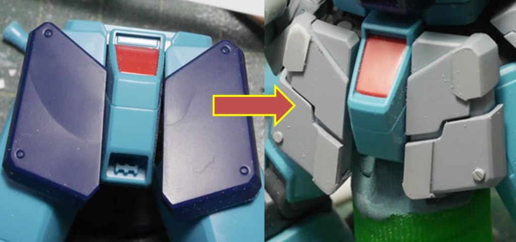
April 20, 2017: I felt that the red bit for the crotch needed a slight bit of detail so I took the scriber and cut some plastic on the sides. It’s relatively simple plastic removal but does a decent job of adding some detail.
Returning to the rear skirts; in the last update, I had just started putting together a scratch built knife and was creating a sheath for it. I trimmed down that plastic piece from the GM Spartan conversion kit and sanded it down to fit into the existing spot on the rear skirt. I also had to sand down some of the internal area for the rear skirt piece for the damn thing to fit. Once the piece fit; I drilled into the plastic and glued a magnet into place. I drilled a corresponding spot on the knife’s guard and added a magnet there. Now the knife is actually held by the power of the magnet instead of friction or just gluing it into place. I wanted the knife functional. A little priming shows areas to fix.
I didn’t want the knife to float on the sheath, so I cut up some plastic stripes and created an outer part for the sheath. Before gluing together, I made sure the knife slides in and out without issue.
The knife is built and a quick test fit into the GM’s hand to make sure it’s not completely out of scale. It looks close enough.
More work on sanding and cleaning up the rear skirts and I have my knife and attachment point and a fully functional sheath for it.
Back to the feet. I had successfully made resin copies. I also successfully casted tons of pin holes (bubbles in the resin) These needed to be cut open and I filled this with Tamiya Light Curing putty. The stuff works amazingly fast. I can putty, sand, prime, and re-putty in however long it takes the primer to cure up.
A few cycles of this and the resin toes are ready to join the rest of the primed parts.
I had made casts of the metal detail bits that I plan on adding to the elbow indents as well as the outer calf armor areas. When I casted them, they pretty much has a sheet of resin on top, so I was first cutting the pieces out and sanding them to fit the circular shape. This was wasting a ton of time and the accuracy was shit. The sanded pieces were not flush, too long on one side, uneven, you name it. Looking over at my tool set to see how I can approach this issue better – my eyes fell on the punch. Luckily, the casted resin detail bits were in mm and perfectly fit the punch set. Any excess resin is sanded, then the whole assembly is punched and I have perfect, round detail bits. The last two pictures are what those parts look like now after getting the alclad metallic treatment.
Those bits are the last details to be primed and for now; I’m done with priming. Everything is looking good so time for a quick subassembly.
And then a quick 90% assembly.
Ok, the real reason I assembled the kit in it’s perfectly primed state is for the next step. A bit of pre-planning for some slight weathering that I have in mind. Using Mr Surfacer 500, a applicator brush and a stiff bristled brush. I apply the Surfacer 500 to a few small areas and then rough it up with the stuff dry brush. This creates a roughed up area that I can use for paint chipping and other weathering effects. I do not want to go overboard so I did very small areas and very sparingly.
How small and sparingly? Well, it’s completely unnoticeable in these three pictures. Zooming in and looking closely it is easier to see, but still, the primer and mr surface 500 colors are the same so it’s hard to distinguish in picture. In person and once it is painted and actually weathered, this will be much more apparent. And hopefully subtle too.
Here a few close ups taken from the above picture that better illustrate what I did.
Now for the paint scheme. I mixed a few colors and have some ideas but I need to work it out a bit before I explain it. The next update will better illustrated the idea I’m trying to do. But alas, I have my colors picked out and have started applying the colors to the kit.
This always happens. While applying the base colors, I always forget that I have glued detail bits into the kit parts. It is much easier to mask off negative space than positive space. So I painted the details on the rear skirt as well as some of the other recessed detail areas and masked it off with sticky tack.
Thrusters are painted and masked the same way. The inner bells are painted with alclad burnt metal. Once cured, they are masked with sticky tack. And then the outer bells are painted with alclad stainless steel. I also picked up some paint pens from my trip to Hong Kong and got around to testing this out on the internal backpack part. It think they look pretty good for paint pens. The extra fine tip is still pretty big, but the silver and gold work quite nicely.
More sticky tack is used to mask off the ankle cover details.
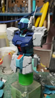
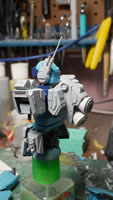
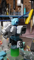
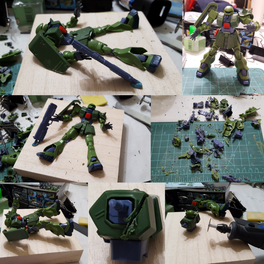
This past weekend was the build gathering. As usual, we drink. So detailed work on this project wasn’t going to fly. Plus, I usually like doing mind numbing tasks at the gathering since they’re not so laborious when drinking and making fun of one another. Earlier last week, I picked up an HGUC Zaku II Kai. This is going to be the center piece of the base I’m building for the sniper kit. So I spent the gathering sanding and gluing the kit only to take a dremel and cut it to pieces. See the collage below:
When the group of us went up to visit Tatsu hobby, I saw a relief kit/figure that looked kinda cool. It was half coming out of a plaque. I figured I’d do something like that in the future. Getting back and letting my mind wander as to how I wanted to display the Sniper – this idea crept back into view. So I cut the poor bastard up and will eventually have it “coming” out of the wood base. I’m actually going to just fade to black on this. The paint scheme has been decided, and the word “Hamburger” comes to mind. Fans of 0080 will get this and either laugh maniacally or be utterly disgusted – either way, it’s cool to me.
In between working on the sniper, I’m working on this kit. I cut up the eye piece. I mean, it was one solid chunk of plastic. Most HGUC kits are like this. Time to lay the groundwork for adding details. I was a bit overzealous in cutting the legs. Well, not so much overzealous but I cut it completely wrong. So the plastic strips are glued into place to add back what I had cut away. Why not just glue back what I had cut away you ask? Well, I had already thrown away the cut away bits. Reason one to hoard your gunpla, even spruce… they may be handy. But, it’s only plastic and this can be fixed. With the plastic trimmed away, its looking closer to my mental image.
Adding a new mono eye just begs to add an LED. So the work to add in an LED starts.
The LED lit up.
And the beginnings of the detailing process – gluing plastic together and filling the holes from when I cut this piece apart.
May 2, 2017: Work has me on travel a bit, and last week, I was in Ecuador, Guayaquil specifically. I did make a quick picture post of the skirts right after getting 90% of it painted up just as a quick teaser and to keep my motivation going. But I didn’t really go into details about the process. So let us backup a little bit to before I even started throwing colors onto the kit and it was still being primed and sanded. The paint scheme I mentally pictured required a little bit of testing before I jumped right into spraying the parts and masking. In the past, not doing the proper color tests and just trying things have bitten me pretty hard on the ass. I mixed up several batches of colors and got to work on spoon testing.
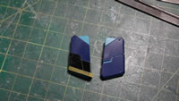
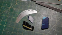
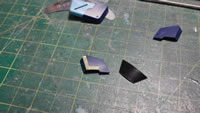
When I was in Hong Kong in March; I picked up some metal templates; a square and a hex. Each template has 4 sizes, the largest on one side, then the other side is split into three sizes. The template is pretty nice for cutting exact size squares or hexs. Tape is just placed on the template, then I used a toothpick to run along the edges to press down the tape, and finally, run a brand new hobby knife blade along the pressed in grooves and I have my cut squares. A test spoon is painted with the first layer of color then the masking and paint scheme tests begin.
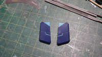
Fast forward the different levels of masking and I was satisfied enough with the results that I could proceed. The spoon test also showed me that I needed to change the masking technique slightly. But the important part of color matching worked.
With the successful spoon test, I start spraying the base color for the parts. I am following the basic color scheme of the standard GM Sniper 2. Light blue appendages with the dark blue chest, skirts, and accent areas. Since I’m using a digital camo pattern for the majority of the kit, the base paint for the lighter blue vs the darker blue needs to be different for those specific parts. I work in the inverse of colors. The light color parts are based coated in Finisher’s wolf blue. The dark blue areas are based coated in a custom mix of Finisher’s lavender and pure white – to get a light lavender color. Starting with the skirts that will eventually be the darker blue. This light lavender color is used as the base coat. When the first base coat cures, the first squares are placed.
I didn’t want to just do a straight digi-camo pattern. Mike Wine had did some net masking on his Sinanju Stein that I thought was really cool and I wanted to try this too. It is a HUGE pain in the ass. But the general idea is to lay down the “net” color. Use the mesh as a masking tool and lay down the main color. So with the skirts’ first layer masked, Mr Color grayish bluey #337 is laid over everything first. Once that cured. Some fabric mesh I picked up at the local fabric store is held over the parts and Finisher’s superfine cobalt is sprayed. This leaves the part with a grey mesh pattern.
Once the above cures, we move on to the next level of masking. Masking off the meshed cobalt layer. Learning from my spoon experiment, I applied more masking keeping the unmasked areas a little tighter between the squares. It is a little interesting to have to think in reverse when doing this kind of masking. But once masked off, the parts are sprayed with Finisher’s wolf blue. Allowing the wolf blue to cure, the mask is removed and I took a quick picture and posted this on a few sites. This was over a week ago and I didn’t get back to work on the kit until I got back from Ecuador last Friday.
So back to the grind this past weekend. I took the skirts apart and started painting the internal frame, the detail bits, and the base part where the cut up outer skirts attach. The rather busy paint scheme hides the amount of detail work, but it’s still not complete, so as this progresses, everything should look better. I hope.
The arms will be the lighter lavender color so the base coat for those starts with the wolf blue and masking for the first layer. Then the whole part is sprayed grey and the Mike Wine net masking is applied followed by the next layer of masking. The final color is the light lavender tone and once unmasked, another layer of masking is done to paint the detail plastic strip that was added in alclad burnt iron. I think there is a little too much negative space around the strip detail, so I will need to go back and spray the darker tones to better balance the scheme.
While the above was happening, the internals and what I like to call the framing pieces for the paint scheme are painted. Again, I did not want to digitally camo the whole kit. I wanted to have breaks between areas; so these frame areas are painted with the solid colors. For these parts, I used a different mix. I used finisher’s pure white with a touch of superfine cobalt to give it a tint of blue. This light framing color will help break up the rather busy camo pattern with a solid color. In the previous skirt pictures, this is the same light blue used on the inner armor piece. The internal details are painted with alclad magnesium, polished aluminum, and polished brass.
The knife is painted with alclad colors. I painted the hilt with a base coat of the framing light blue color then sprayed finisher’s pearl white over to get a pearled effect. Pictures here do no justice and it’s hard to see the pearl effect. But it is a small part and will be at the back, so unless looking really closely at different angles, it will be hard to see in person too.
Returning to the earlier statement that the Mike Wine net masking technique is difficult. I ended up screwing it up while painting the rear skirts. So the only thing to do is to sand this down and start over.
The main body work started a few days ago with the masking over the base light lavender tone. The main chest piece doesn’t work well with the net masking technique so I decided to forego that for this piece as well as the backpack. The shoulders and legs will still get that net treatment. I’m not sure how this will eventually match up when I’m all said and done, but I decided on this for the interest of the deadline I’ve set for myself. Instead, I added some striping that cuts diagonally down the right side of the chest.
Mask, paint, mask, and the final wolf blue is sprayed then the masking is removed and the inner torso piece is added back. Notice that the inner torso piece is painted the same framing light blue as the arms. Again, using this as a means to break up the camo pattern. This is the same color as the inner piece to the skirts. Things are starting to come together.
The rest of the parts are in the various stages of paint. Being out of county for a week really puts the drive back into working on the damn thing. Unfortunately, my work has a bunch of trips lined up and Those Gundam Guys in general have a bunch of events coming up that will severely impact progress. Short cuts cause fuck ups as does rushing, so I need to constantly remind myself to slow the F down when I do get time to work on this.
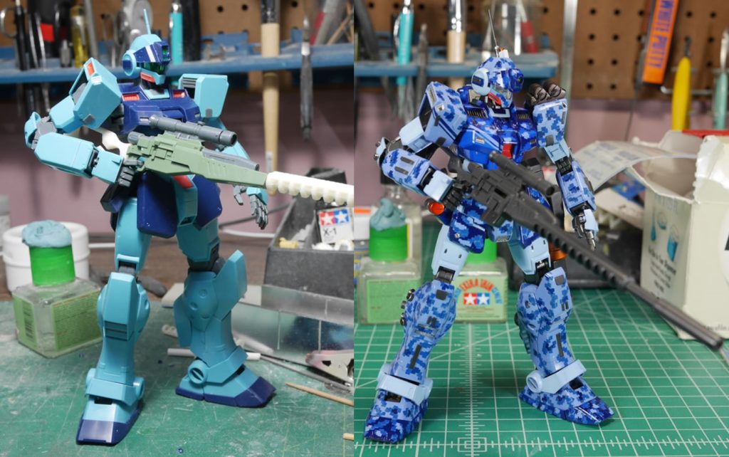
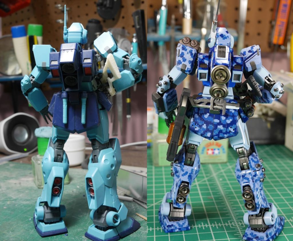
May 15, 2017: Its been two weeks since the last update post. There were a few busy weekends where not much progressed and all the work in these past two weeks was just the endless cycle of paint-mask-paint-mask. So this will just show you how f-ing tedious that process was and hopefully show that it’s actually worth the grinding. The last bit of work done last night was spraying the clear gloss over the kit. Several coats of clear gloss. And the reason for this will become more apparent as we progress through this update. Before taking the kit apart into small subsections for the clear gloss, I snapped a few assembled pictures. It’s a good time to bring back the snapped pictures I took over 3 months ago when I first started this project to get a side by side comparison.
Frontside:
Backside:
Returning to the rear skirts, I reprimed and got the base colors down and started the first layer of masking. Small bits here and there. Then the cloth hex mesh masking and painted with cobalt blue. And then the next layer of small square masking. Then the removal of the masking. The problem with so many layers of masking is that the paint will build up and you end up with very uneven paint. One solution is to lightly sand each layer of paint with a very high grit sanding pad. This polishes the paint and helps level things. To avoid having to sand over the paint, I try to keep the layers of paint thin – but when there are colors that take a heavier layer to show; this is unavoidable; so the high grit sanding pads come out to play.
The chest block is masked off and painted. Because of the problem I ran into with the rear skirt when I tried the cloth hex masking (I didn’t have a picture of the process while I worked on most of the kit – but later in this post, I have a picture of how I did the leg). The process I was using would make it very difficult to actually look halfway decent on the chest and backpack. I decided to skip that step and just use the cobalt blue alone. This kind of bites me in the ass later when the kit comes together and there is a tonal difference from the rest of the dark blue parts. I’m hoping that once I get all the clear coats, decals, weathering, this difference will be less glaring.
Once the upper torso and most of the waist are done; a quick assembly helps to get a better look at the progression. Metal mesh is added to the vents and the kit is actually starting to take shape. Putting things together when I finish also helps check against tonal differences or even the fit. With enough paint sprayed, things that were tight before without any paint are near impossible to assemble. So this is a good exercise in making sure it all still fits as designed. And it is a sense of accomplishment.
For the left shoulder, I added some canisters akin to the GM Spartan’s shoulder. But I wanted these canisters to be smoke grenades or just smoke dispensers. I figured as a sniper, the smoke dispensers would be a good defensive tool. Doing some research online for real world smoke dispenser on tanks, I found that they were usually connected with a chain. I thought this looked cool so I added a very small chain that I found at the local railroad store. Once I drybrush it a little, the chain should stand out more; but for now, the shoulders are done.
I’ve been making update posts on reddit and our TGG FB page. One of the users on reddit pointed out that my masking for the head’s cheek vents was sloppy. Our camera phones have gotten so good with high resolution pictures of tiny thing; that when I got home, I couldn’t actually see the issue. Well, I could if I looked REALLY close. I went ahead and fixed it anyways. It’s always good to get comments about the kit as you’re working on it so that it’s never too late to fix issues that I miss.
Returning the the shoulder. I had masked off and painted the detail areas but noticed that the different paint layers is too noticeable. The part is masked off and the detail bit is sanded down then repainted. This goes back to earlier in the post when some high grit sanding pads are useful in leveling out things as you continue to paint.
The shoulders are now done and can be added along with the arms that were completed a few weeks ago and we almost have a complete upper torso. All I have left are the legs and feet.
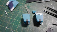
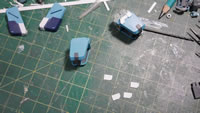
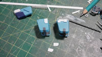
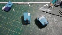
Since the legs are going to be the same light tone as the arms. I first sprayed the dark wolf blue color, then applied the first masking layer. The next step is to spray the bluish gray. This will be the hex color. The hex effect is done with a cloth mesh. The mesh is held against the part and cobalt blue is sprayed. The problem with this technique is that the mesh isn’t completely attached to the surface. Now if all the parts were flat with no raised details, this would work beautifully and the hex lines would be very crisp. But the cloth is raised here and there so there are blurry feathered lines. Now if that’s the effect you want, then you’re set. I was looking for something more crisp and precise; but I was experimenting with a technique my friend Mike Wine did for his Sinanju Stein. It’s not until later that I found a FB site that was selling hex masking. In the grand scheme of the project the blurry hex lines are not too big a deal because I’m not using the hex masking heavily. I just want a subtle hint that there’s some hex masking sandwiched between the digital camo. The thighs were also painted with the lighter cobalt blue mixture around this time too; they were masked off with parafilm so that the remainder of the leg painting continues.
Once the hex pattern is cured. The next layer of masking is applied. Using the metal template, squares are applied. This process takes hours. The payoff is less than 2 minutes of airbrushing with the lighter lavender tone.
It takes longer to remove the masking tape than it did to airbrush. But thankfully, not as long as it did applying the damn little squares. And once all the masking is removed, bits of the armor pieces are remasked to paint up some of the raised details.
With all the painting done on ONE leg, the armor pieces are separated to add in the metal mesh details. I had drilled out the holes for the inner calf details and originally glued them into position. I did not want to mask and paint the mesh, so I removed them while I painted the kit. The mesh was also brass in color. I found an aluminum colored mesh from the local railroad hobby shop and grabbed that. I didn’t want a brass colored mesh, so having the aluminum one lets me skip the paint/mask process if I did use the brass. The punch is brought out and the mesh is taped to a thick sheet of paper for support. The mesh is pretty delicate; so if I just used the mesh in the punch, I would end up wasting more mesh since the punch wouldn’t be completely clean. The added cardstock support helps get clean cut circular mesh pieces. Once the mesh is cut, they are just glued to the back of the calf piece and the rest of the leg is assembled with some mesh on the vents below the knee. The work on just one leg took most of the week.
The bottom of the feet are painted and masked with alclad metallics. The feet tops are also painted. Originally, I had the dark blue areas of the lower foot a solid color. But decided to apply the digital camo pattern. I’m not sure that was the right decision. It looks a bit on the busy side. I didn’t want the upper foot to have such a stark contrast with a solid colored lower foot since I already had the ankle covers a solid color. I’m still on the fence about this. And in the interest of time, I will most likely leave it, unless it really starts to bother me in the next week or so.
The feet and one leg is done. Time to assemble an entire leg!
Going back to my first test fit with some metal bits that I had casted in resin. The painted bits are added to the elbows and outer calf to complete the arms and leg. It was pointed out to me that these details may be a bit too large. I agree with the elbows, but it is an interesting look and kind of matches up with the absurdity of the extended thrusters I have on the kit. As a whole, I think it balances decently. In previous updated, the arms were commented as being a little too skinny. Again, a few days of looking at this should help me decide if I wanna go back and fiddle with it.
Since I had the one leg done and the other leg was still in the process of being painted. I did a quick assembly to get a better look at how the kit comes together. Light at the end of the tunnel indeed!
This is the first weekend where I have a decent amount of time to dedicate to the project. So the second leg was finished much quicker than the first. The unmasked mess:
We had a build gathering this past weekend. So along with getting a good amount of work done on the last leg, I also got some work in on the display base. Returning to the HGUC Zaku FZ, the cut up suit is glued to an acrylic sheet. In an earlier update, I had been a bit overzealous when I cut up the right leg. I had to glue back some styrene and putty back the mess, so that part isn’t glued down to the acrylic base yet. I need to putty/sand/paint/ and recheck that part for mistakes before slapping it down onto the acrylic with the rest of the body parts. The chopping tool is used to cut up some styrene tubes to create new cables for waist and head. The stock cables for HGUC kits never look good. I start with a piece of 26 awg gauge wire as the base cable; which is wrapped with 28 gauge magnet wire for detail effect; then the wrapped wired is sleeved with cut styrene tubes for the waist. The same 26 awg is used for the head wire but using 34 gauge magnet wire to wrap that before adding in a cables cut from a slightly thinner tube. The last picture of the set looks almost Han Soloesq with the acrylic sheet standing up.
The last leg is done and I did a quick test fit with everything for a very quick photoshoot.
Additional angles. I think it’s looking fairly decent. Things will now slow down a bit as I work on the clear coats, decals, weathering. But it shouldn’t be too long before the star of this project is done.
After the photoshoot, the kit is disassembled and skewered for the coats and coats of clear gloss. The clear gloss will help level out the uneven digi camo byproduct surface. It will also help with decal adhesion by giving the surface an ultra smooth platform.
