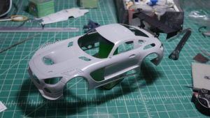
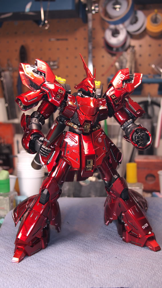
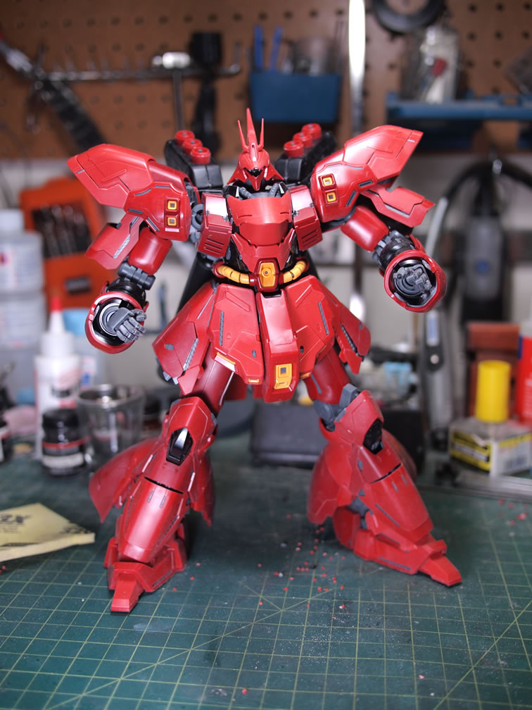
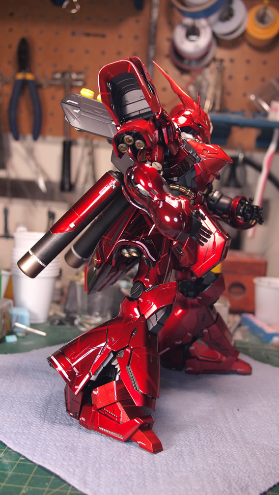
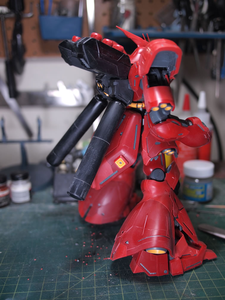
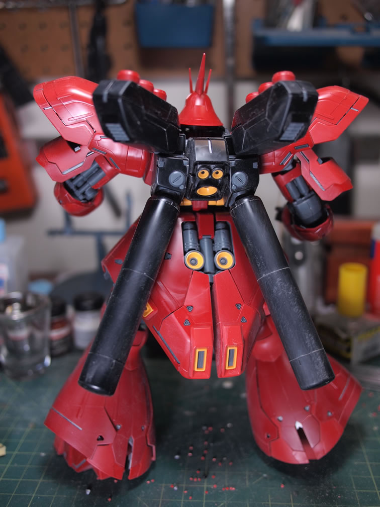
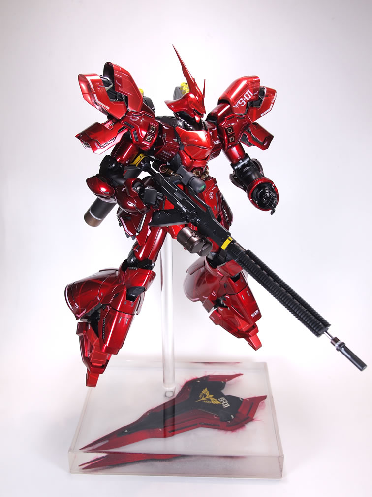
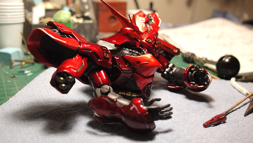
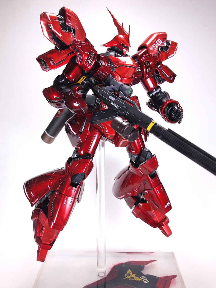
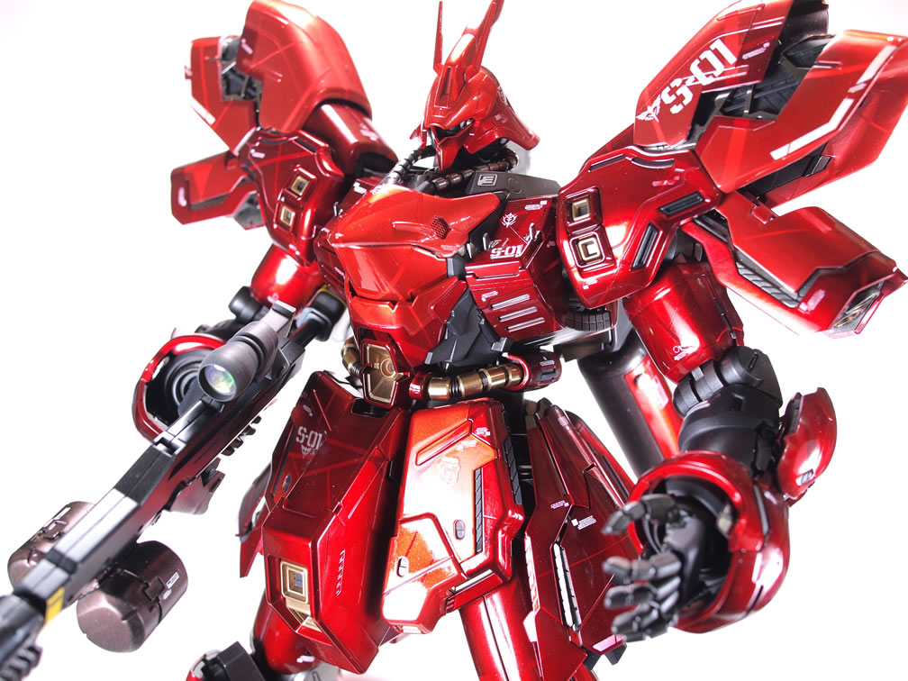
Weekend update: Ver Ka Sazabi get’s completed! Since my last update, I’ve gotten the third section of the kit painted, the weapon systems done, all the wiring for the 35 or so LED on the sucker wired up and working, and finished the rather simplistic display base. Here’s a quick little comparison between the finished kit and the snapped up kit.
Short list of mods:
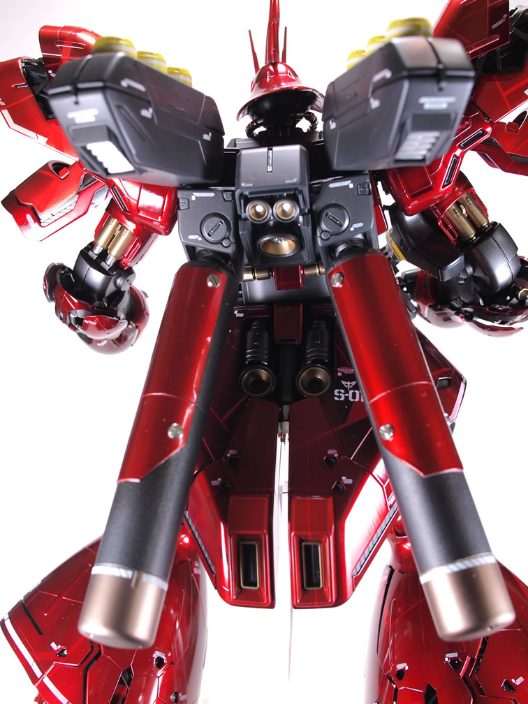
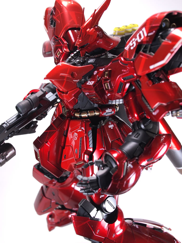
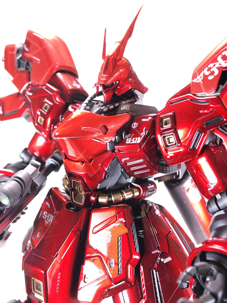
- The upper torso chest piece was beefed up and reshaped. The slits were filled with styrene and a hexagon cutout with mesh inserts wad added.
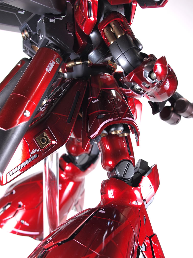
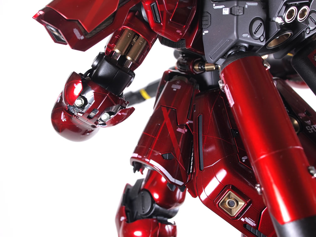
- The neck cables were replaced with a magnet wire spring, wiring, and metal collars.
- The waist cables were replaced with magnet wire and metal collars.
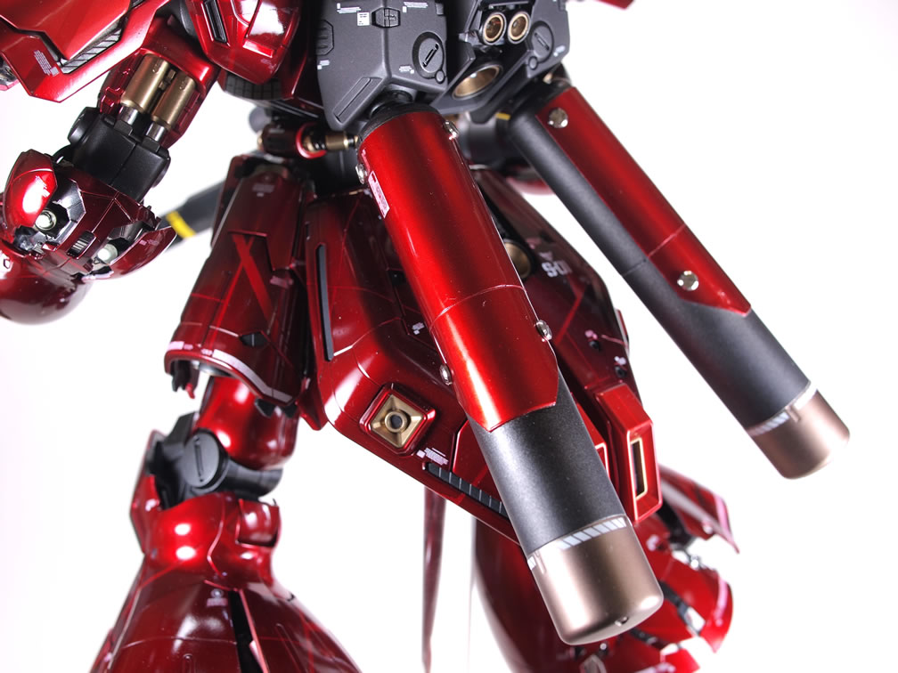
- Fuel tanks added some styrene and metal minus mold details.
- Head antenna was extended with styrene.
- Back of the head was extended with styrene.
- Shoulder ends were extended and flared out slightly with styrene.
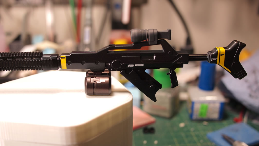
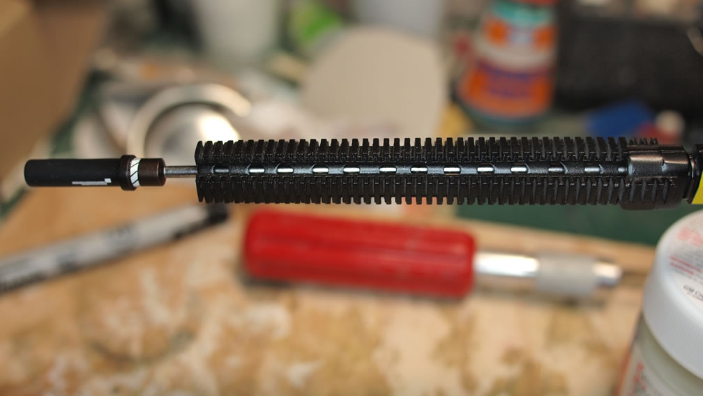
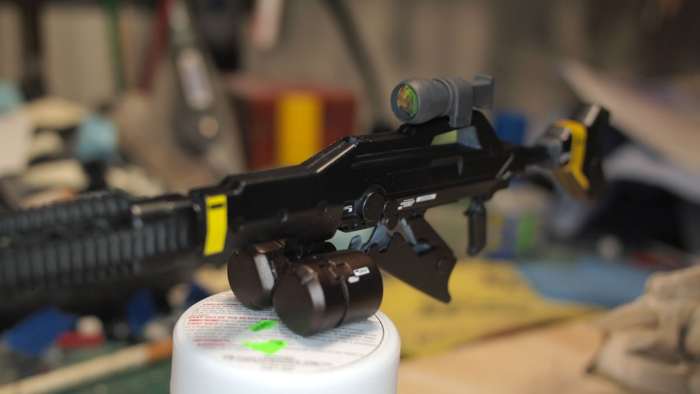
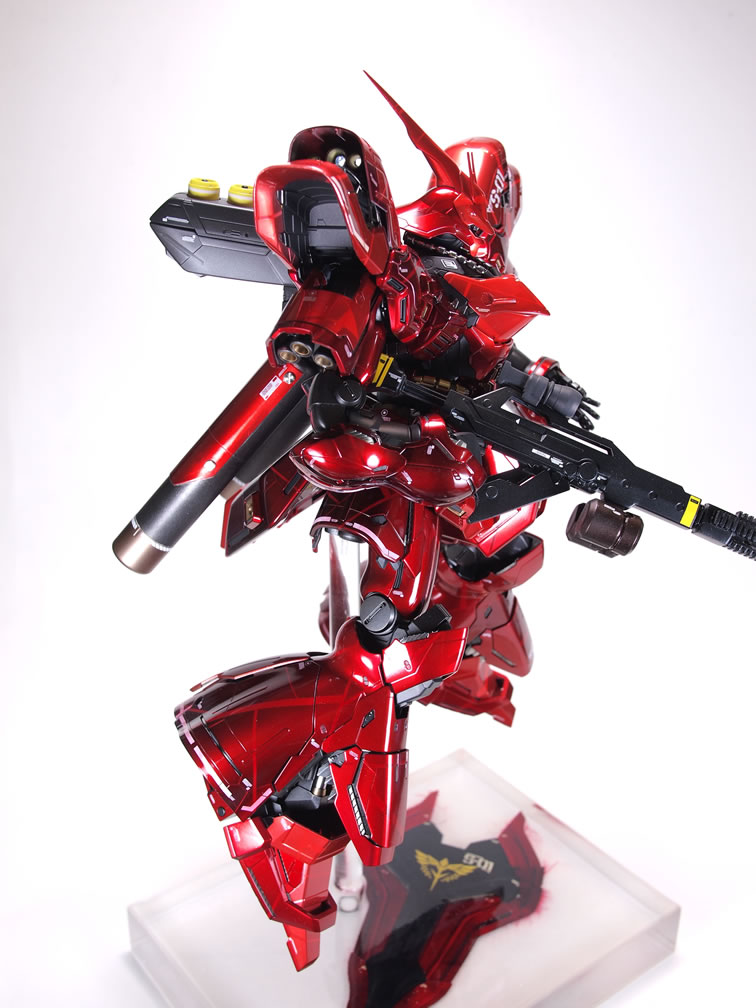
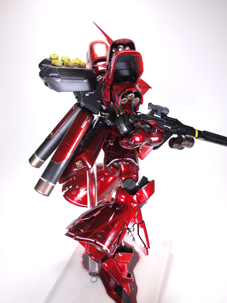
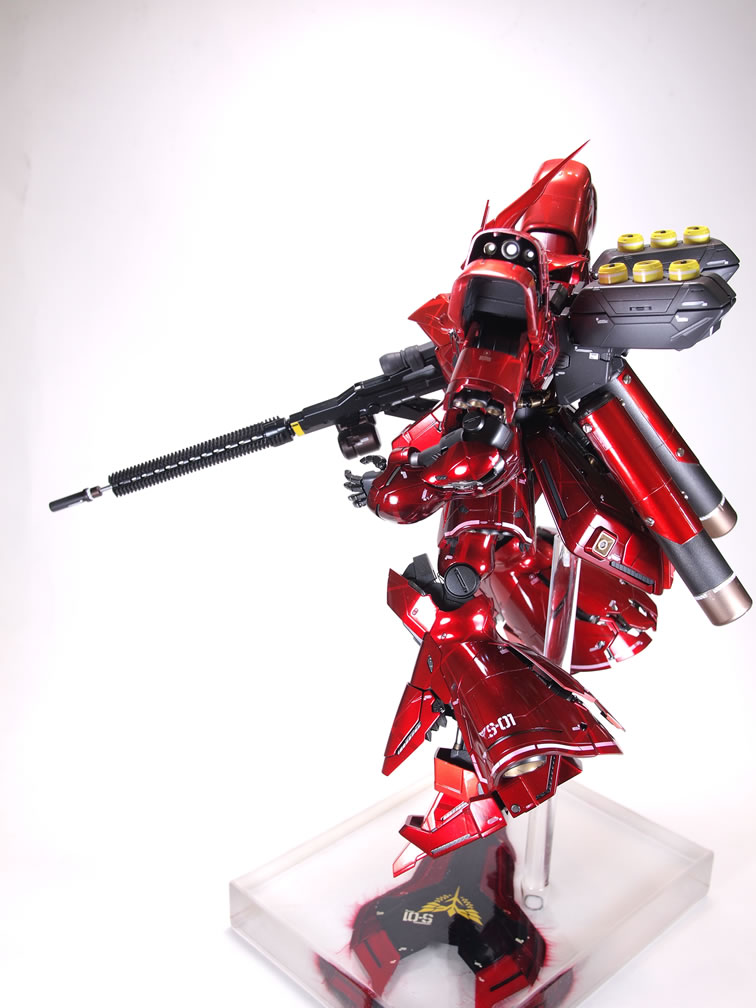
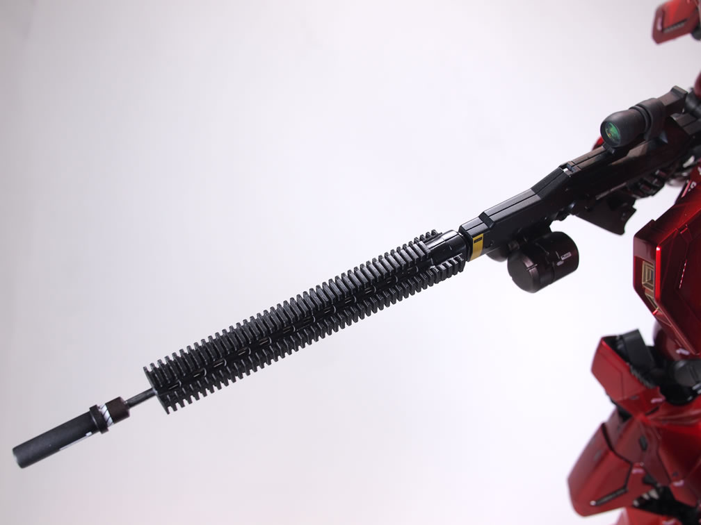
- The Sazabi long rifle was cut and modified with a scope, dual ammo mag, free floating RIS system, over a ported outer barrel encasing an inner barrel, with a silencer. (yes, why would a GIANT robot need a silencer, very good question. I have no idea how to answer that… um… because it looks damn cool, yeah, that’s the answer!)
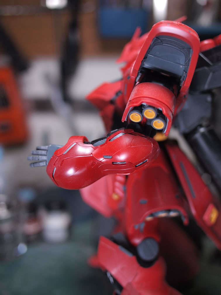
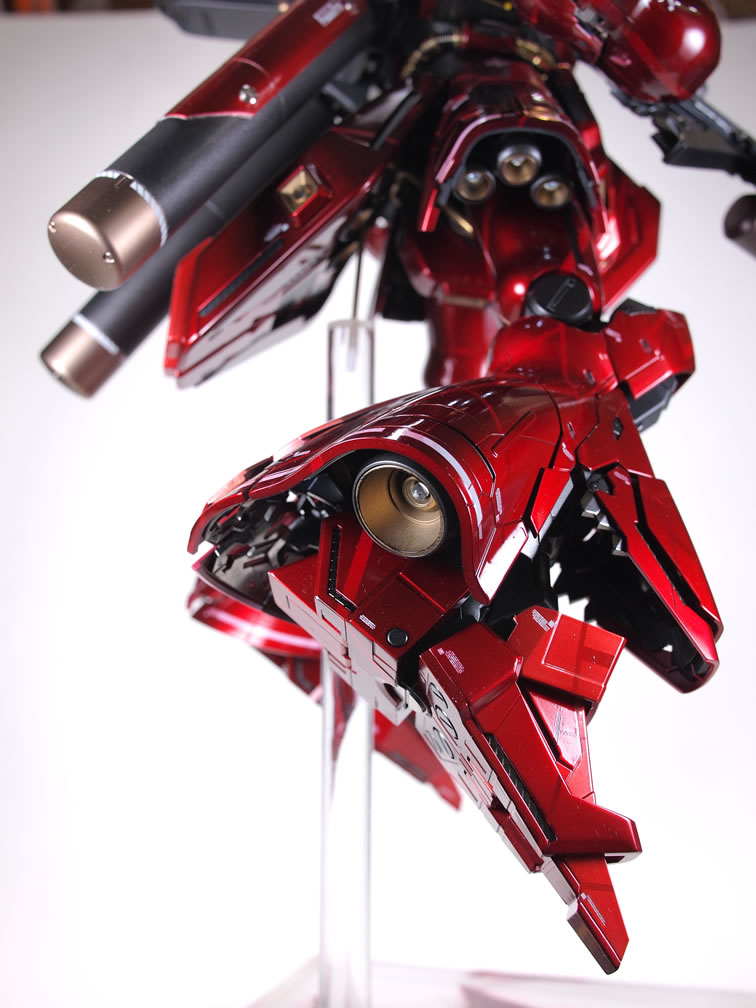
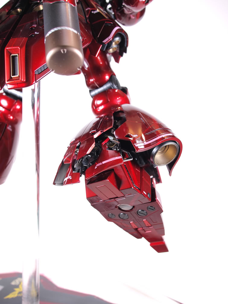
- Mono eye modified with a metal collar to focus light in one direction.
- 36 LEDs in total, 35 of those cast in resin thrusters and wired up to a reed switch and battery assembly.
Read about the final bits for this build as well as the full set of completed pictures after the jump!
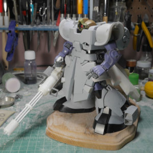
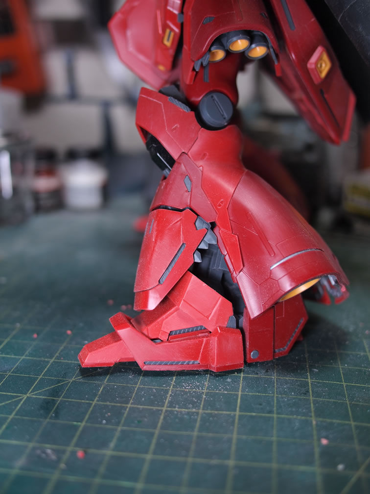
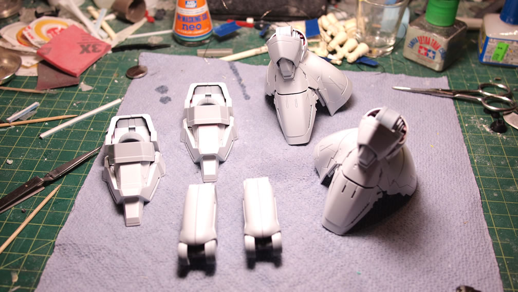
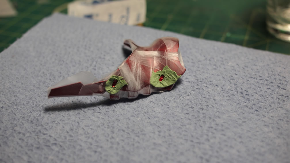
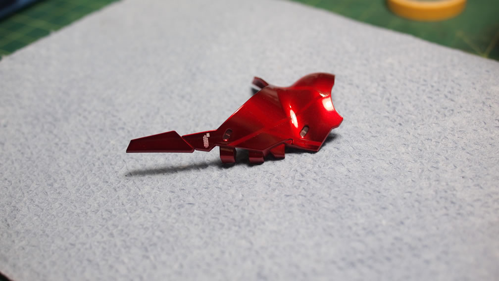
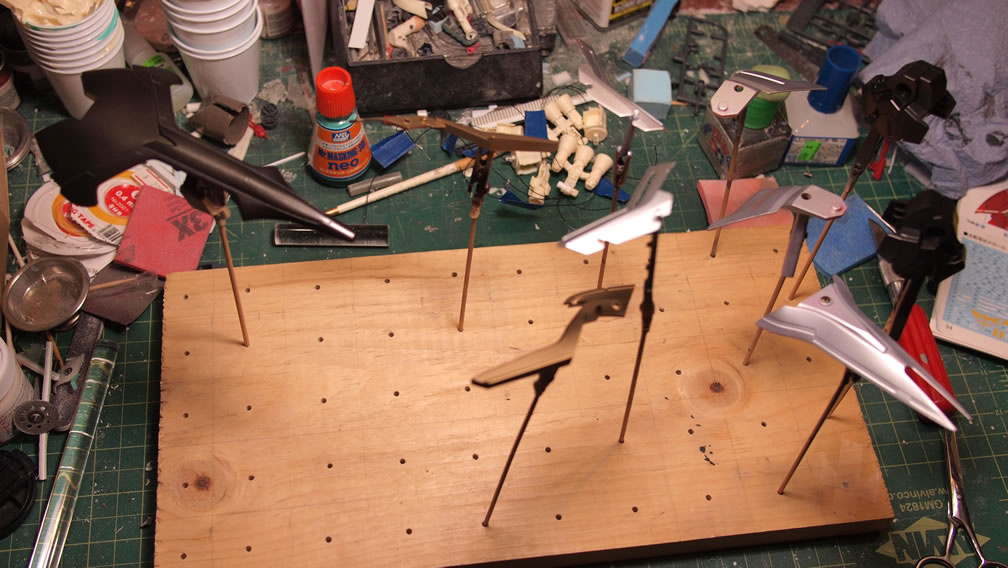
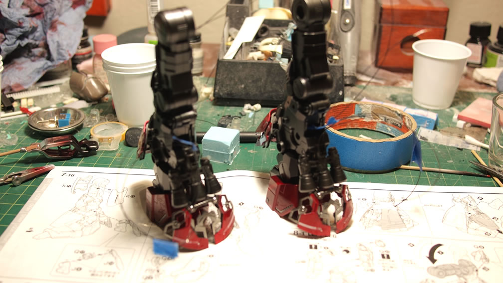
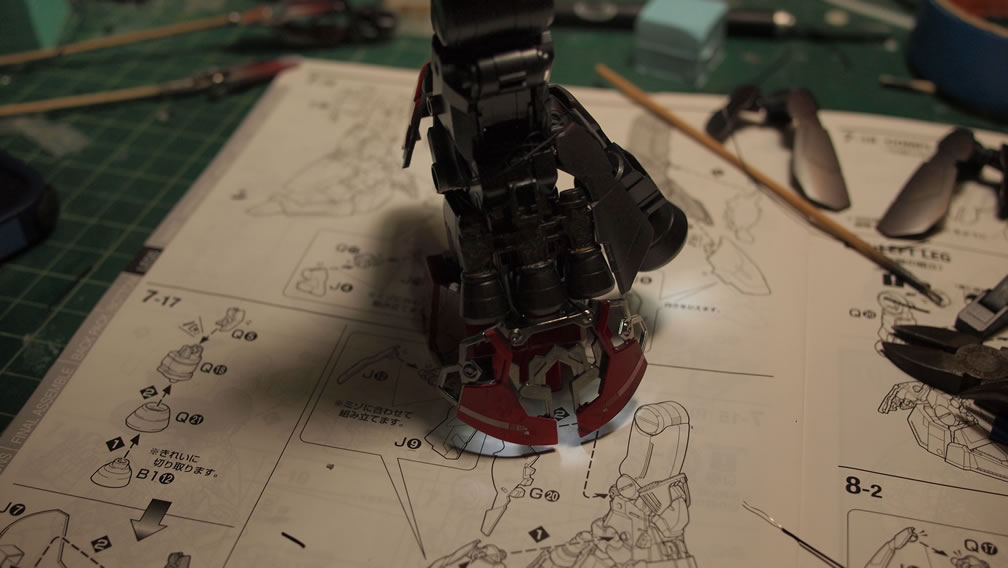
The last third of the third building group, the legs, get painted in the same fashion as the other two sections described in earlier posts. White base over the grey primer, masking, metallics, unmasked, the clear reds.
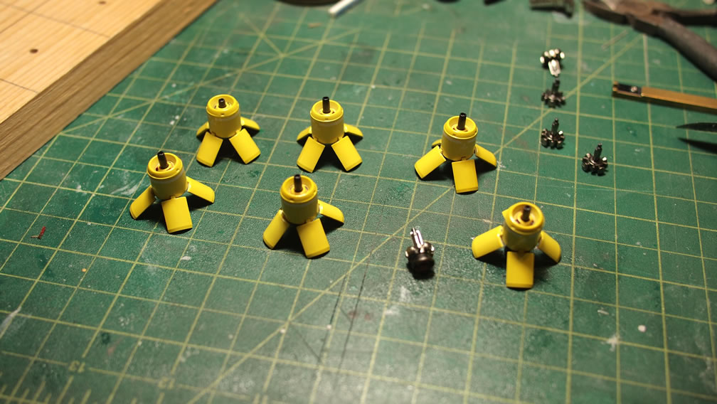
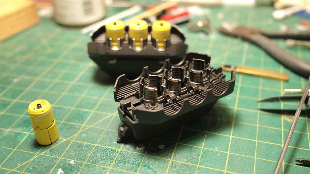
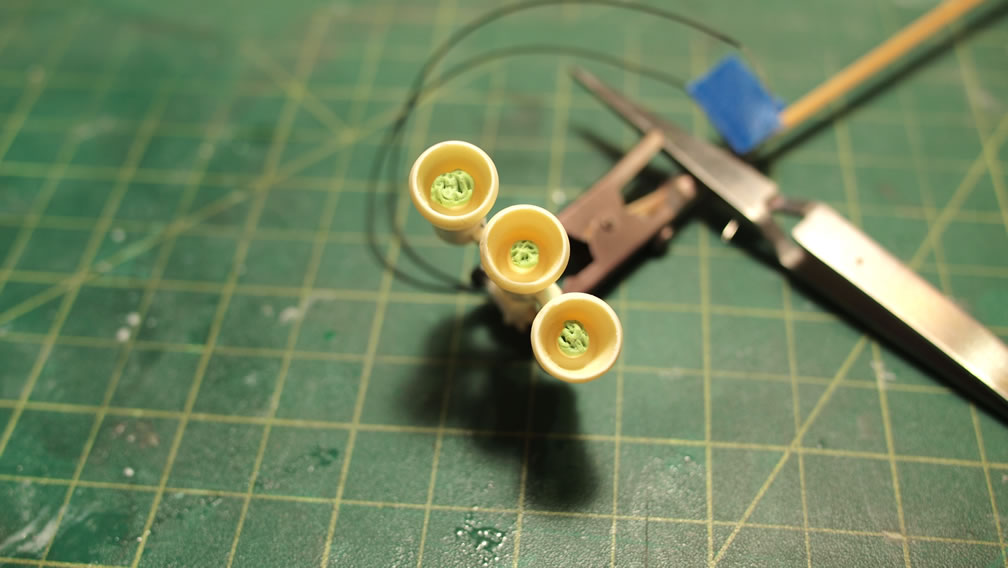
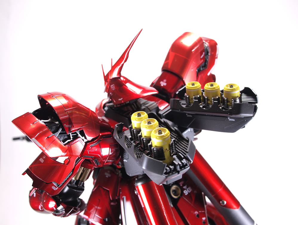
I decided to use the funnels as a means to break up all the red, so I first sprayed them with white base. In hindsight, I should have first sprayed these red parts with mr color primer, then sprayed the white base. Too much red was bleeding through the white. Over this white, I sprayed Mr Color clear yellow, so the funnels are a bright lemon yellow. The internals to the funnels were painted with various metallic tones and then assembled and decaled. With that done, they were assembled into the funnel pods.
The rifle progress was shown in an earlier post. I finally got that finished with paint and decals. The main rifle was sprayed first with Mr Color Metallic Black (Metal Black) depending on what label you stumbled upon, but it’s the same product number. Over this to lower emphasis on the rather large metallic flakes, I sprayed alclad gun metal with worked to tone things down slightly.
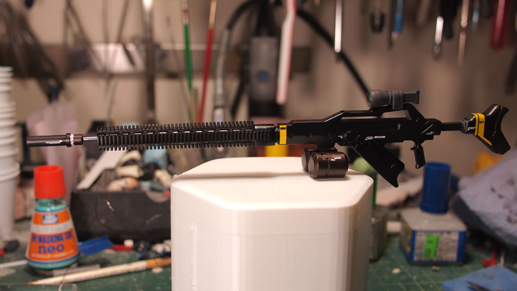
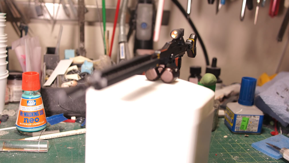
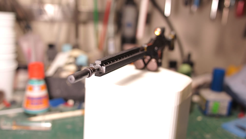
Close ups for the rifle. The scope lenses were done with aurora stickers from ako hobby. The silencer got a dual tone finish with Alclad burnt iron fading into the Mr Color Metal Black/Alclad Gun Metal combination.
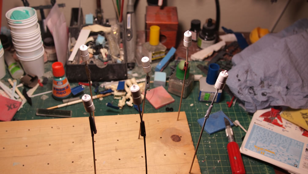
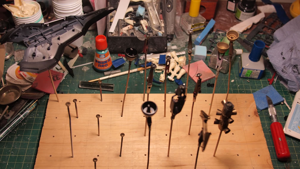
The LEDs embedded in the resin thruster parts were masked off then painted with Alclad steel. The backpack thrusters were cut up and LEDs were fit into the spots and wired up internally. And a quick test with a battery ensures it all works.
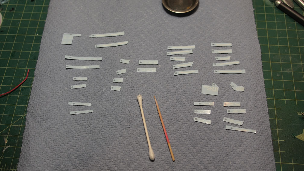
One of the things that made working on this project so fluid with cutting up the kit into three sections was the decals. Doing the kit in three distinct parts was similar to working on three distinct kits. Paint, decals, clear. The decal sheet for this kit was fairly daunting, so cutting up the kit into three parts really helped. The following decal layout is for the lower leg pieces only.
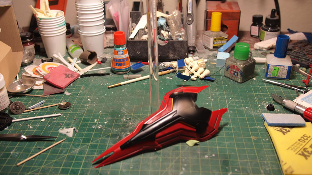
With everything painted, decaled, and clear coated. A few days of curing was set for the parts before they were masked to paint the small details. I could have easily gone in and hand painted these little details, but the texturing would have been completely off. So parafilm and sticky tak was used to mask off the areas for some quick sprays of Alclad burnt iron.
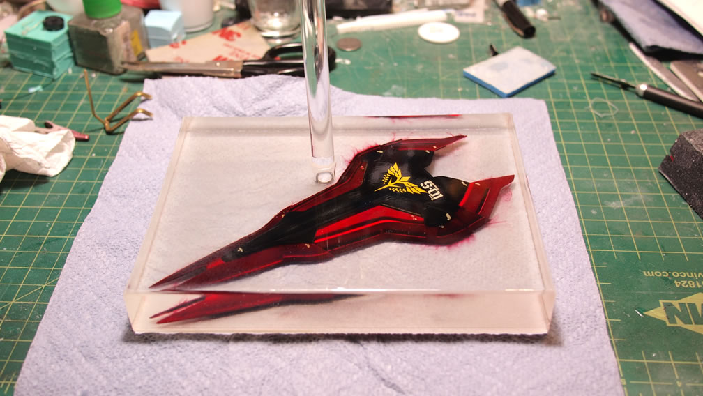
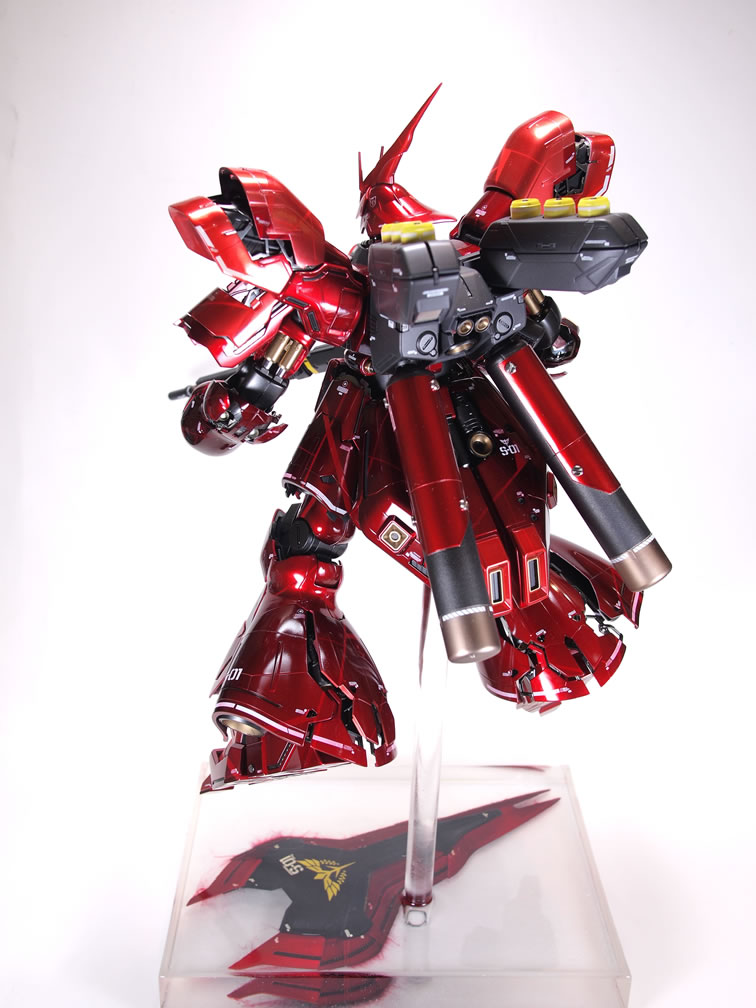
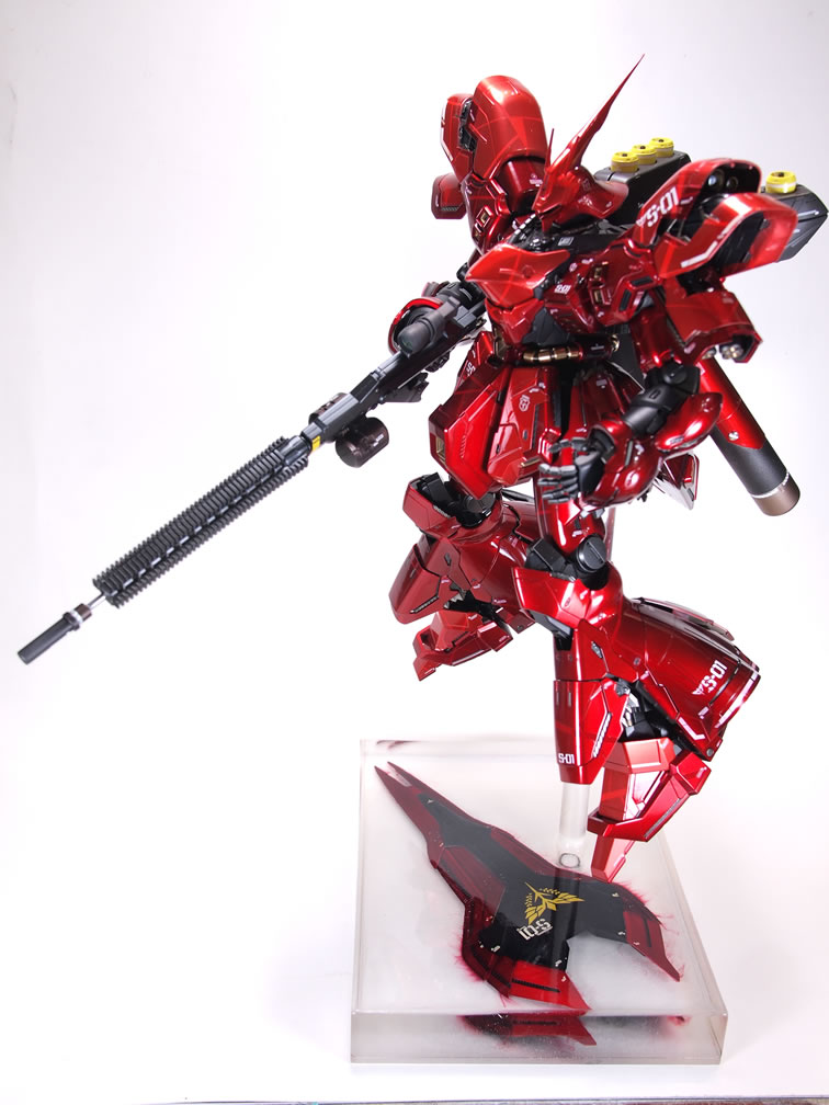
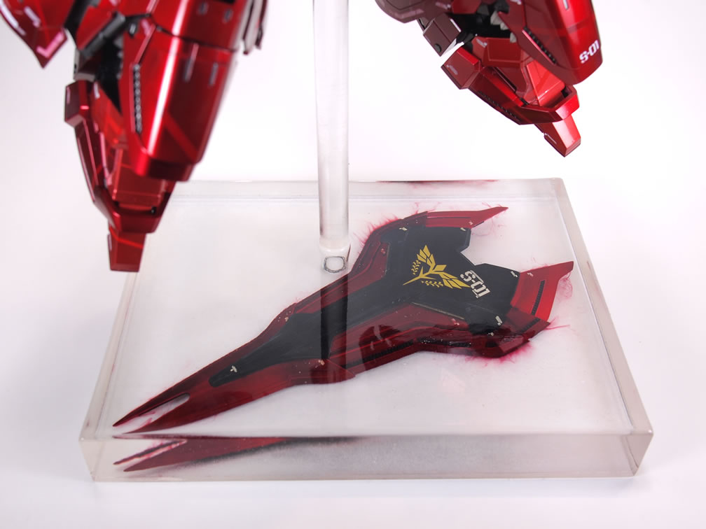
I love the Sazabi design. I love the shield. However, having the Saz holding the shield obscures a good third of the body and work, so this is my solution to displaying the shield with the kit. Use the shield as part of the base. And for a base, I wanted something simple so as the focus on the display is the Sazabi, not everything else around. The solution, encasing it in a block of clear resin.
Starting off, the kit was built, painted, and decaled. In hindsight, I should have let the damn parts cure for a full week and/or clear coated the parts before rushing into the next step.
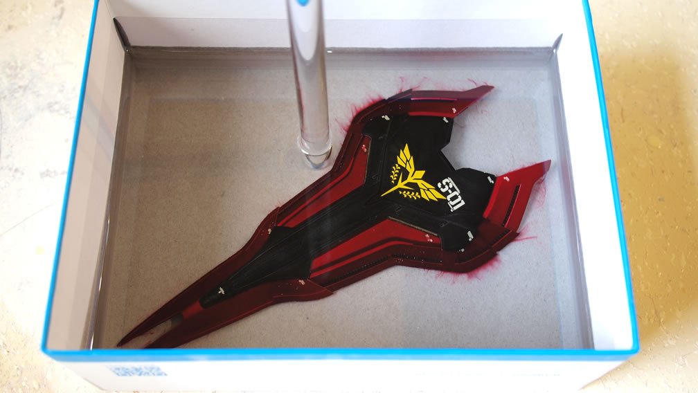
Using a box from my Resin SD Kampfer, I first layed down a thin layer of polyurethane clear resin. That dried and cured fairly quickly, and since the box didn’t fit into my pressure pot, it had to be cured in the normal atmosphere. So since the urethane cured so quickly, there are a decent number of tiny bubbles trapped and visible as the bottom most layer.
With the base layer cured, the shield was placed into the box and I mixed a large batch of enamel clear resin that has a much slower cure time. The slower cure time also helps as the process isn’t as exothermic as the urethane resin curing. It would be a horrific shame if the curing clear resin melted the shield. However, I wasn’t completely unscathed, not allowing the paint to cure and not clear coating it led to the paints bleeding. Granted it does kinda look cool, but it isn’t what I was intending to do. To quote Bob Ross, “we don’t make mistakes, just happy little accidents” I guess.
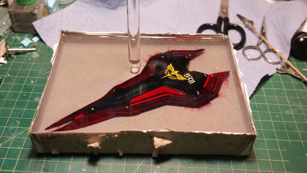
The first layer of enamel clear resin didn’t cover the entire shield, so it was left for about a day and a half to solidify, then another layer of enamel resin was poured. This layer found yet another “happy little accident”, and bubbles from air trapped within the shield surfaced. The resin cured for another day and a half so the bubbles were hard enough to cut apart and clip off some of the excess. The last layer of enamel resin was poured, and using a bamboo skewer, I poked around the bubbled areas to ensure that the resin filled in those spots, and that really worked to help remove the bubbles from the previous pour.
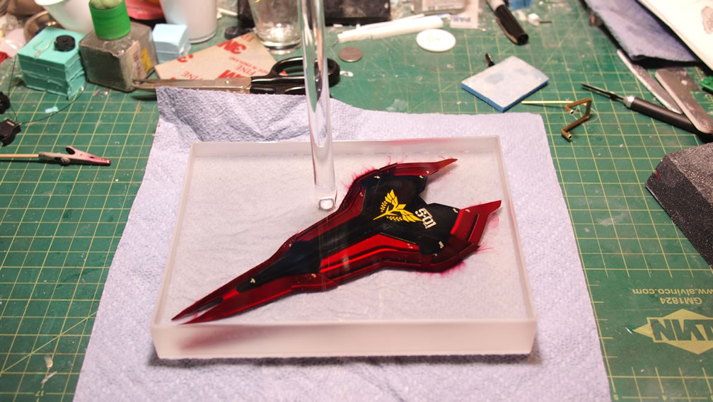
The resin pouring process happened a few weeks ago, and after checking the hardness over the past week, this weekend was good for finishing the base. The box was cut apart, but some of the box is still sticking to the cured resin. After all, resin is an adhesive. So with most of the box cut off, the entire block and clinging cardboard was soaked in water for several hours. Soaking helped peel away more of the cardboard. Another soaking session removed the rest of the cardboard, but left a sticky residue. The residue is sanded away leaving the clear resin block free of any paper products. A quick spray of clear gloss along the sides makes everything water clear.
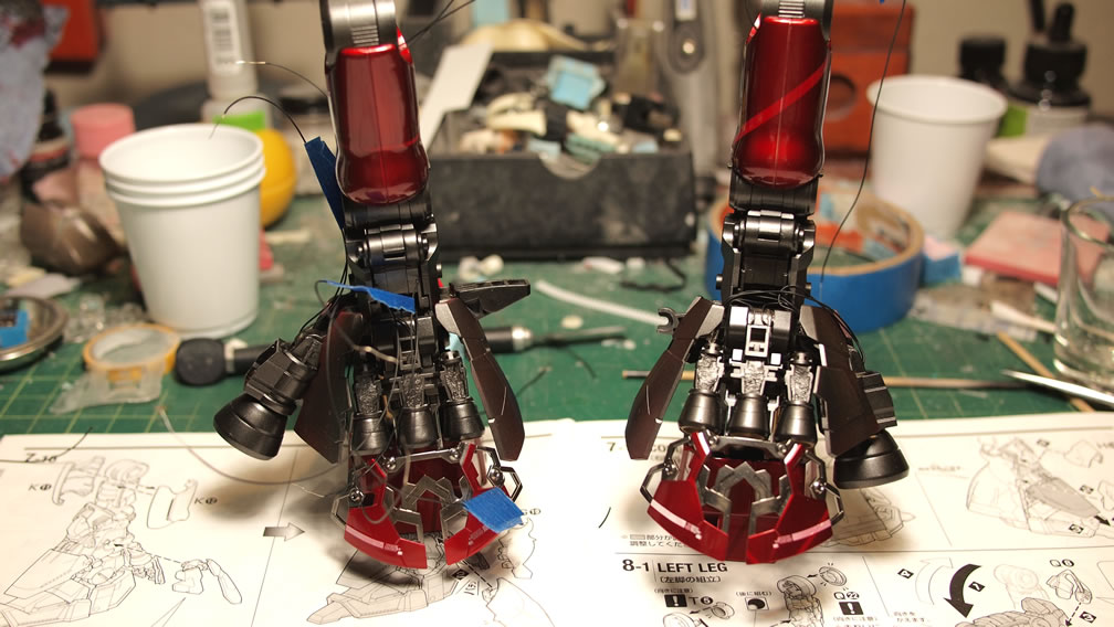
Last week saw the wiring from the painted resin thruster pieces through frame parts of individual sections. Each leg piece holds three separatly wired LED assemblies, the front thruster, larger rear thruster, and the 3 part rear thruster.
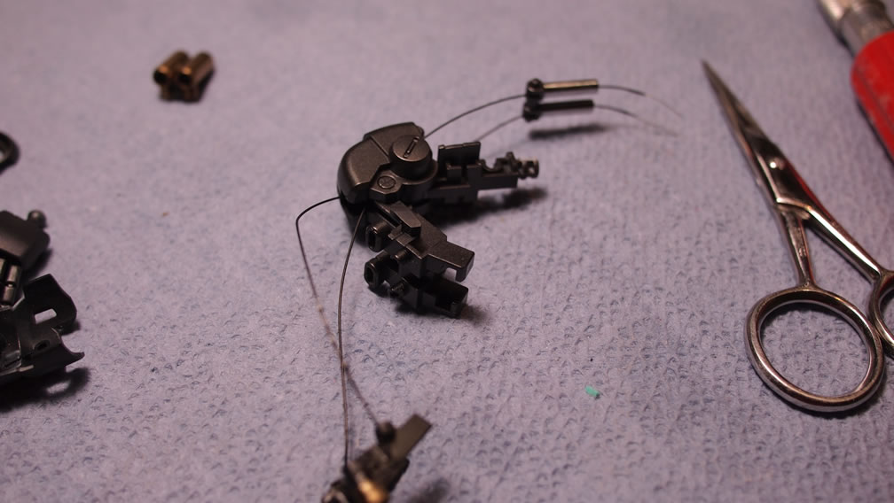
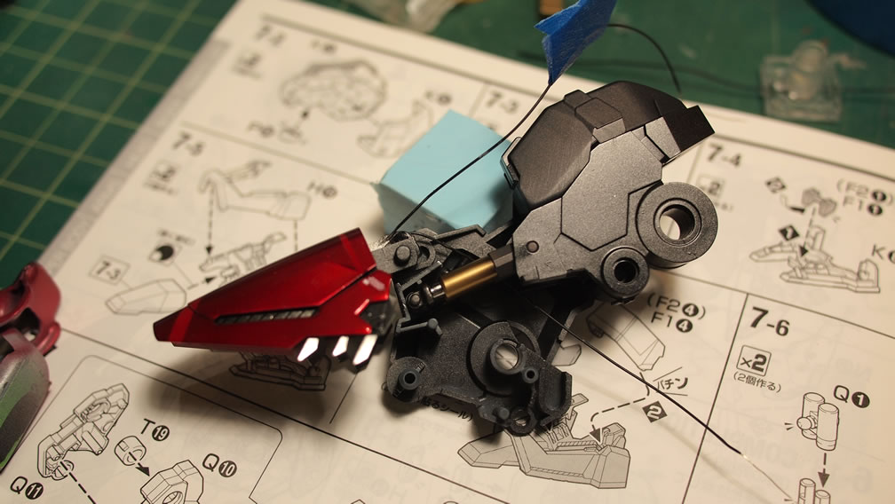
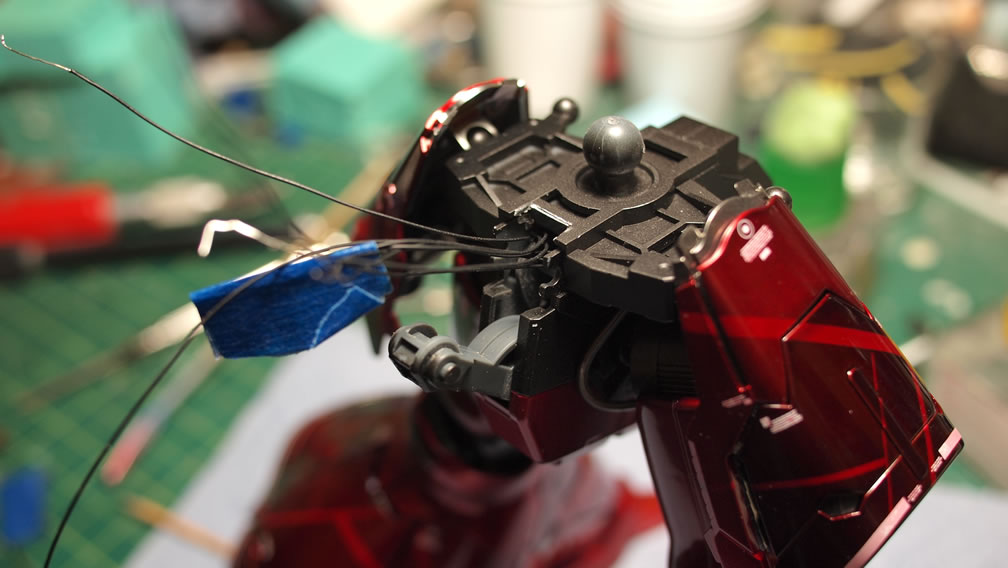
As the leg is assembled, the wiring is threaded through and the three sections are wired together at the back of the knee area. Below is a comparison of the mess of wiring with the wires tied together neatly to form a single positive and negative pair that is then threaded up the rest of the leg. The wiring is tested out to make sure all three sections are lighting up.
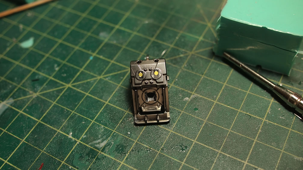
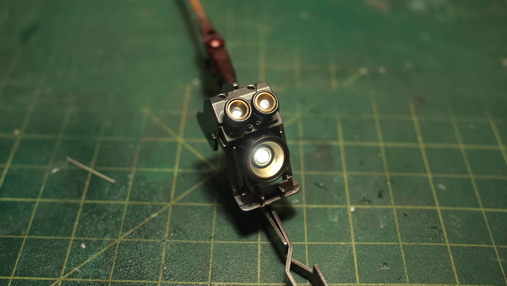
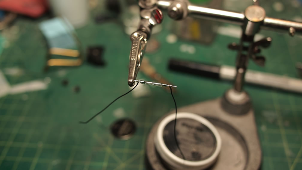
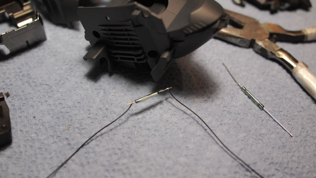
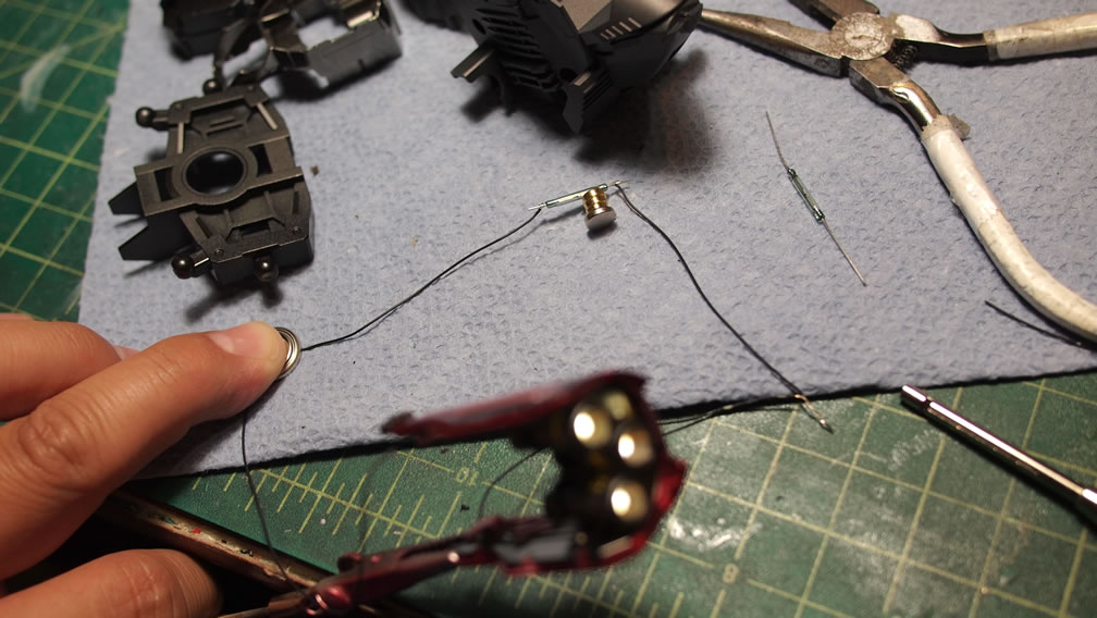
Next up is the reed switch assembly and test. The reed switch is a magnetically activated switch and makes a connection with a magnetic field is close by, in this case, a small rare earth magnet. From the LED assembly, the positive end is run to one end of the reed, and continued through the other end of the reed switch to the positive end of the battery source. The negative end of the LED assembly is run directly to the battery. The reed acts as a break along the positive wiring. Connecting a magnet, the wiring is completed, lighting up the LED assembly.
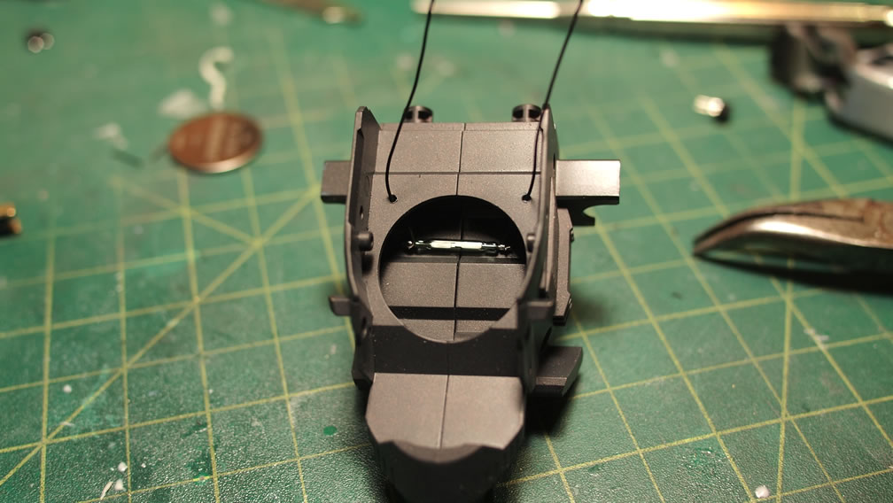
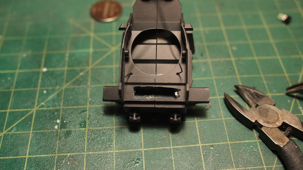
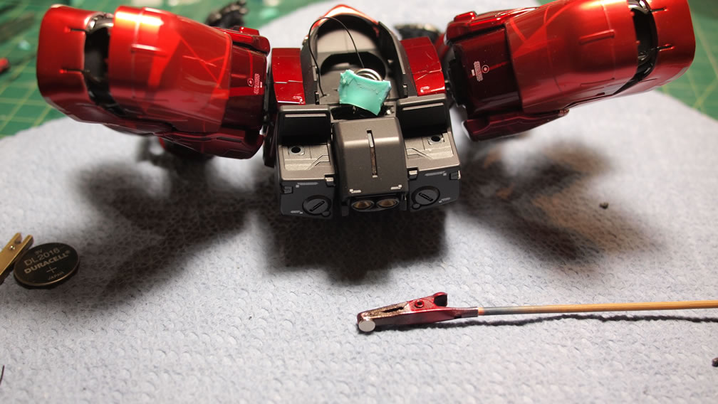
With the test successful, the reed switch goes into the neck/collar piece. It is wired and glued into position.
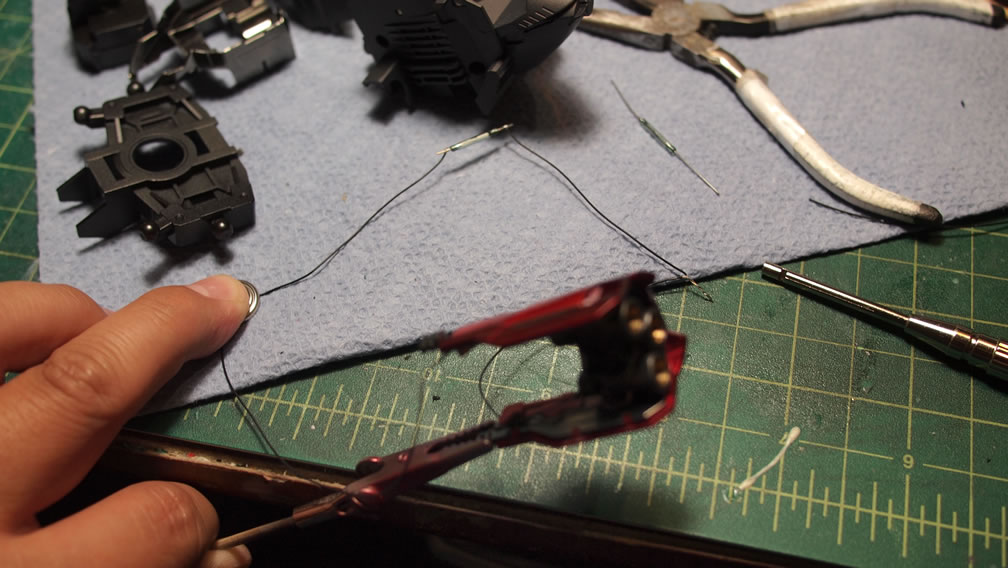
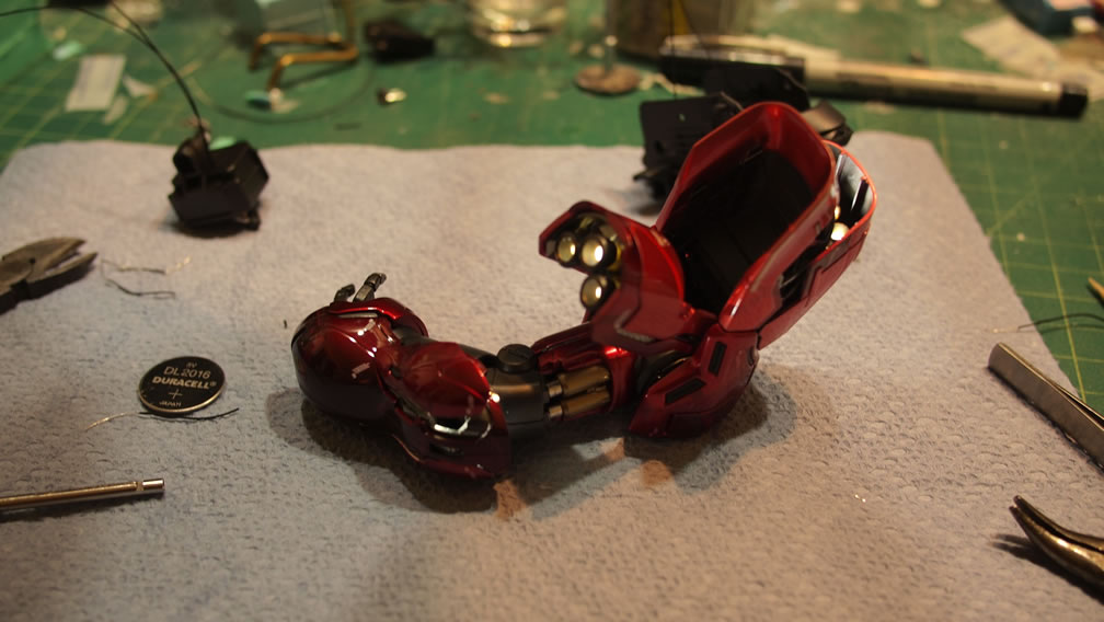
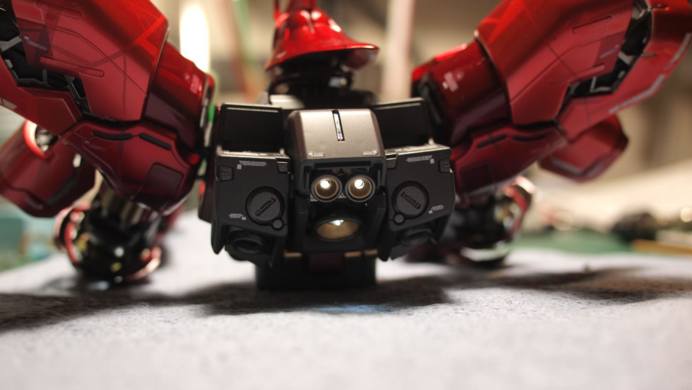
Returning to the arm sub assembly, the three thruster parts here are threaded and wired together similarly to how the legs are wired. Three parts combining into a single positive and negative pair that runs out of the lower shoulder connection joint. A quick test of the arm lights show that everything works.
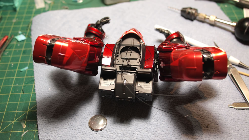
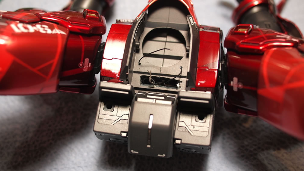
The arms and backpack are assembled to the upper torso piece along with the battery and reed switch assembly. The negative ends are threaded through the body and wired together as well as the positive ends wired together and connected to one end of the reed switch. The other end of the reed switch connects to the battery’s positive end. The negative end just connects to the combined negative wires tied together.
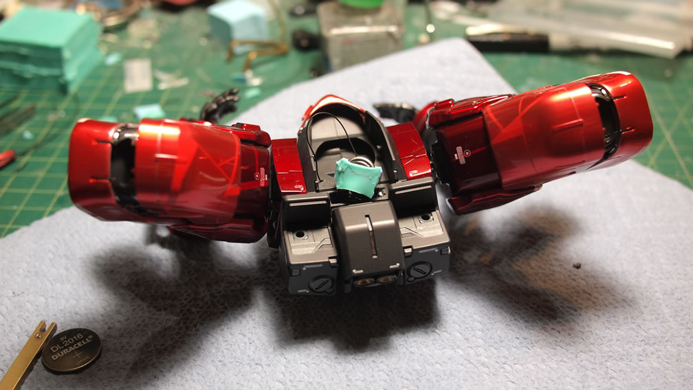
Another quick light test of the upper body, this time with the battery and reed switch assembly. I’ve also added a simple connection that runs down the length of the upper torso. The waist will have a companion connector point so that the entire suit is wired as separate upper and lower entities. This will make traveling with the kit easier.
Lower torso is wired together, the legs and waist skirt lights are combined along with the connector piece.
With the wiring completed and the two halves of the Sazabi connected, I did a quick little video showing off the lights as well as the reed switch in action.
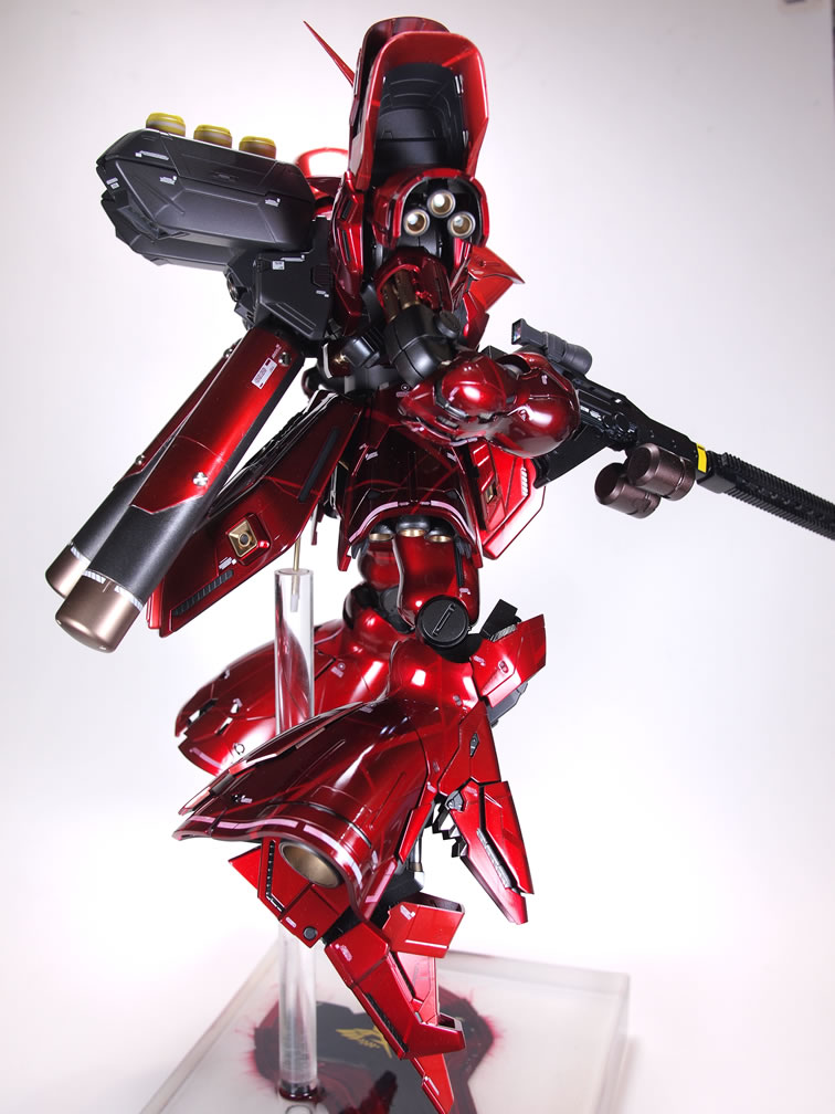
And with the base completed last night, here is everything:
|
|
|
|
|
|
|
|
|
|
|
|
|
|
|
|
|
|
|
|
|